 Alexander Williams
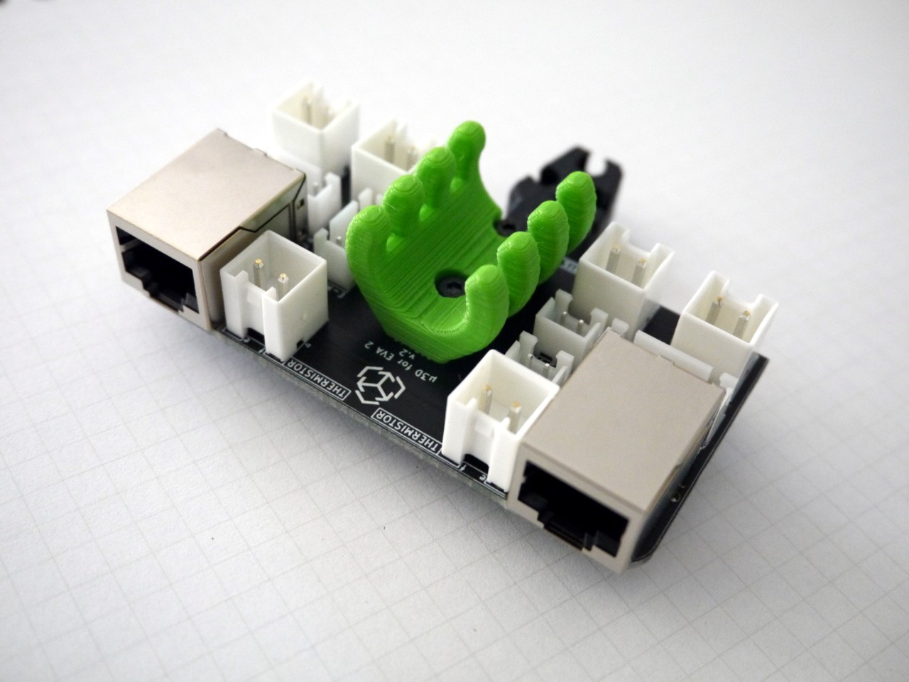
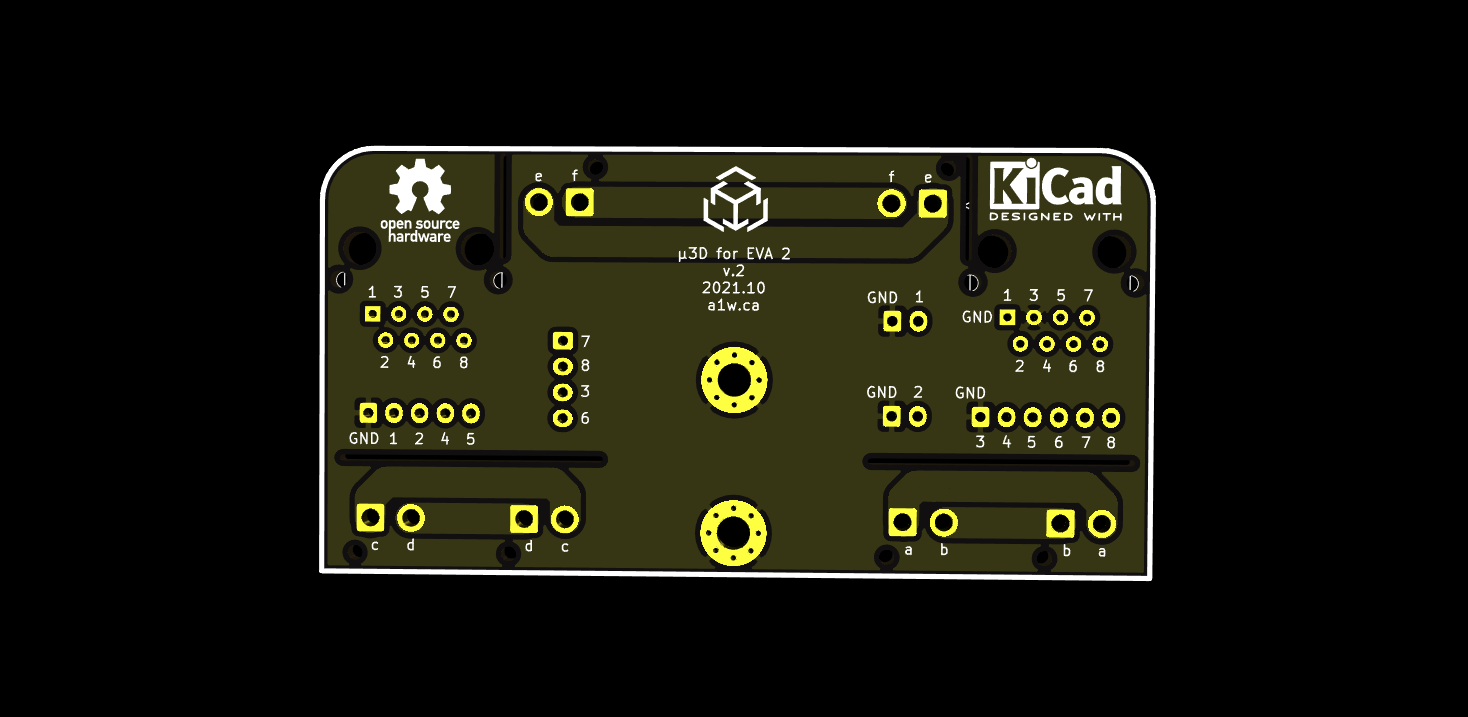
This board is designed specifically as an addon for the EVA 2 3D project which enables modular 3D printer hotend assemblies using standard adapters and 3D printed parts.
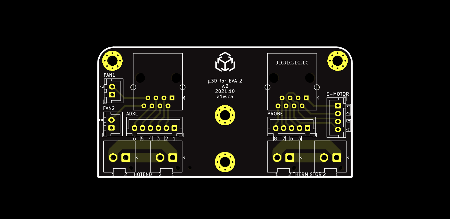
The v2 of this board is designed to route wiring for the hotend heater cartridge or the hotend thermistor.
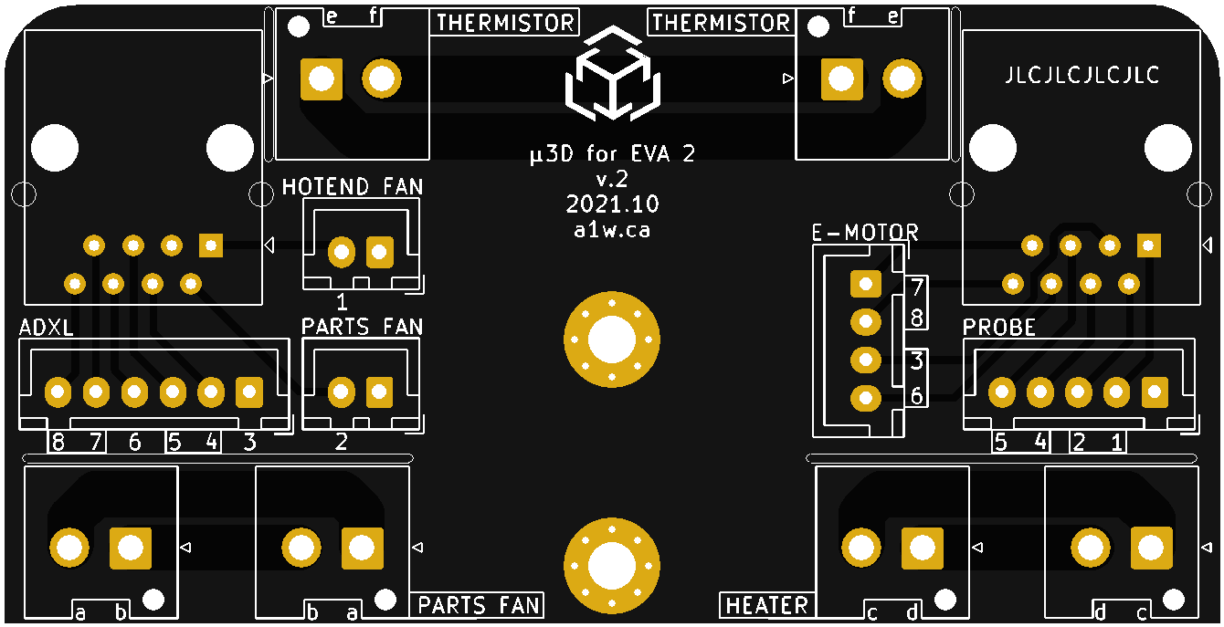
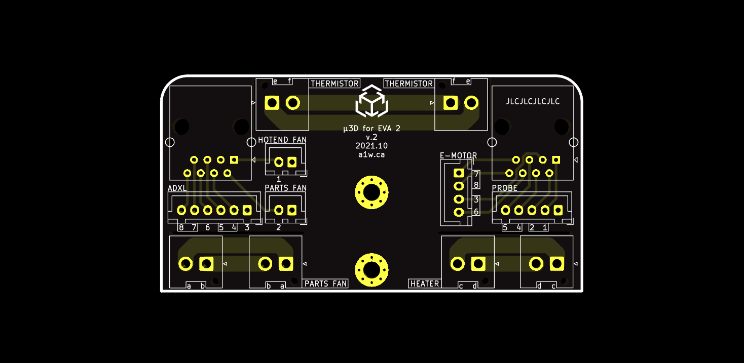
Board design notes
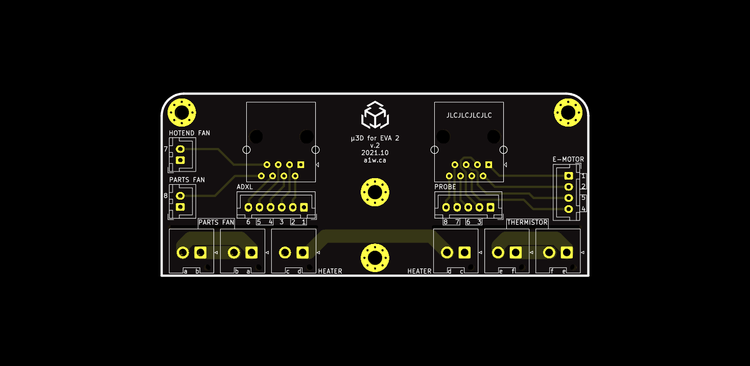
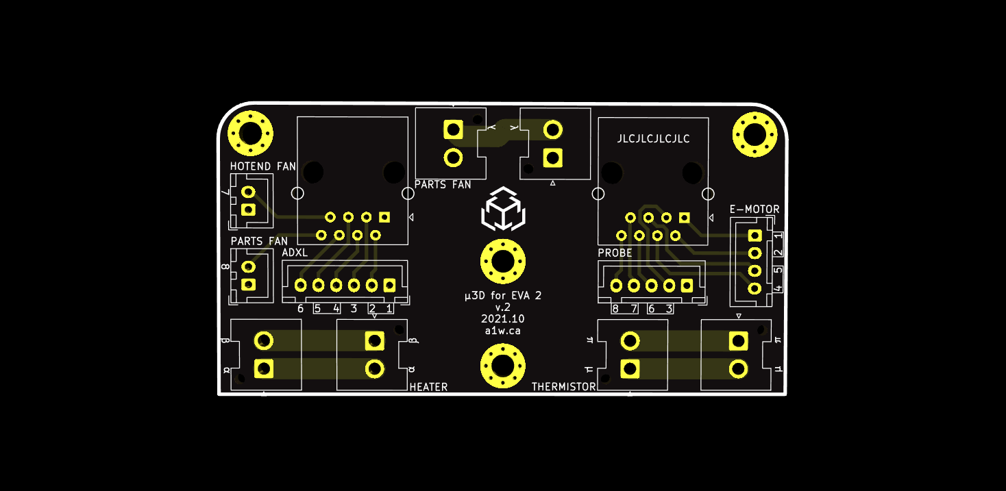
- PCB traces to RJ45 and JST-XH connectors (small) are 0.500mm and should handle 1A of current on each pin
- PCB traces to JST-VH connectors (large) are 3mm and should handle 3.9A of current on each pin (2A tested), but could possibly handle more since the traces are duplicated on both sides
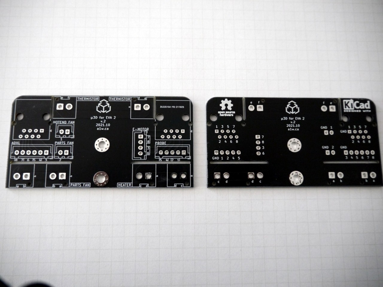
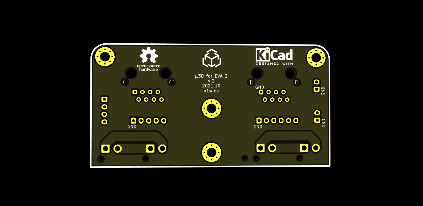
- GND is connected to the M3 mounting holes and shared with other pins labeled GND
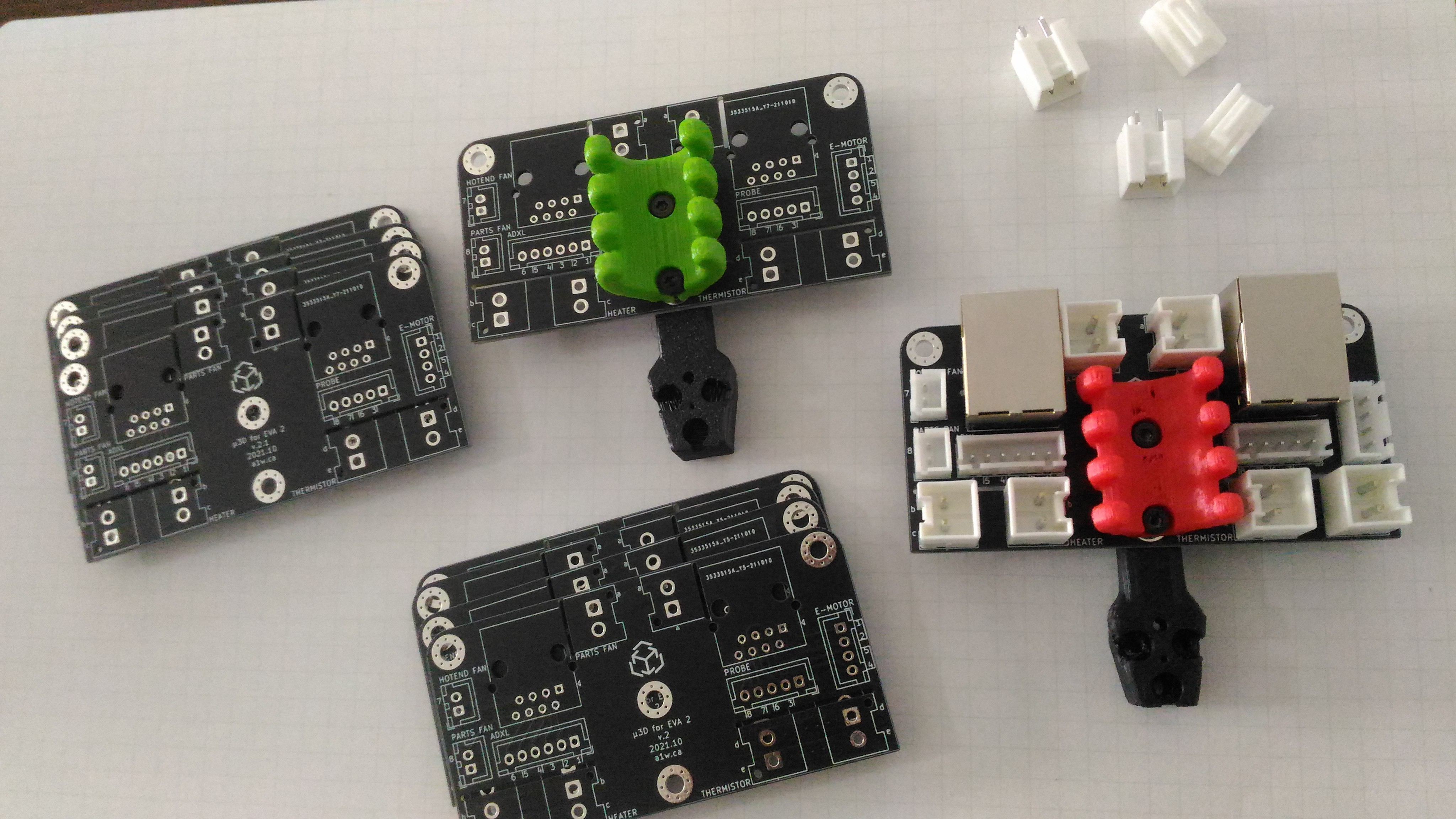
- JST-XH/JST-VH connectors are recommended, but other connectors/pin headers may be used
- RJ45 connectors are shielded but don't contain LEDs, so the board draws 0mA current.
- The board is mounted using 2 screws and sits between the universal_cable_mount and cable_holder -- it doesn't require 3D printing additional parts.
This project is certified open hardware:

Other solutions
There's a few other interesting solutions out there, with various useful features:


 FrazzledBadger
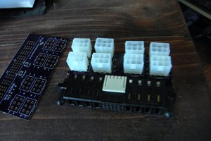
 Charles Lakins
 MagicWolfi
 Simon
Simon
Could you post pictures of how it looks in the printer itself?