If you'd like to follow along the debugging journey, I suggest you scroll down and click: 'view all # project logs' and sort from oldest. Otherwise the project logs read back to front!
I am always grateful to receive donations of faulty Amiga or 486/Pentium era PC hardware to repair and restore. Particularly keen on the big box Amiga's such as the Amiga 1000, 2000 and 3000 that I've yet to come across. So if you have any systems, or Zorro/ISA/PCI Graphics/Sound/Network/I/O cards that you can bear to part with and would be willing to donate for restoration, please let me know! I'd be most grateful to take it off your hands!
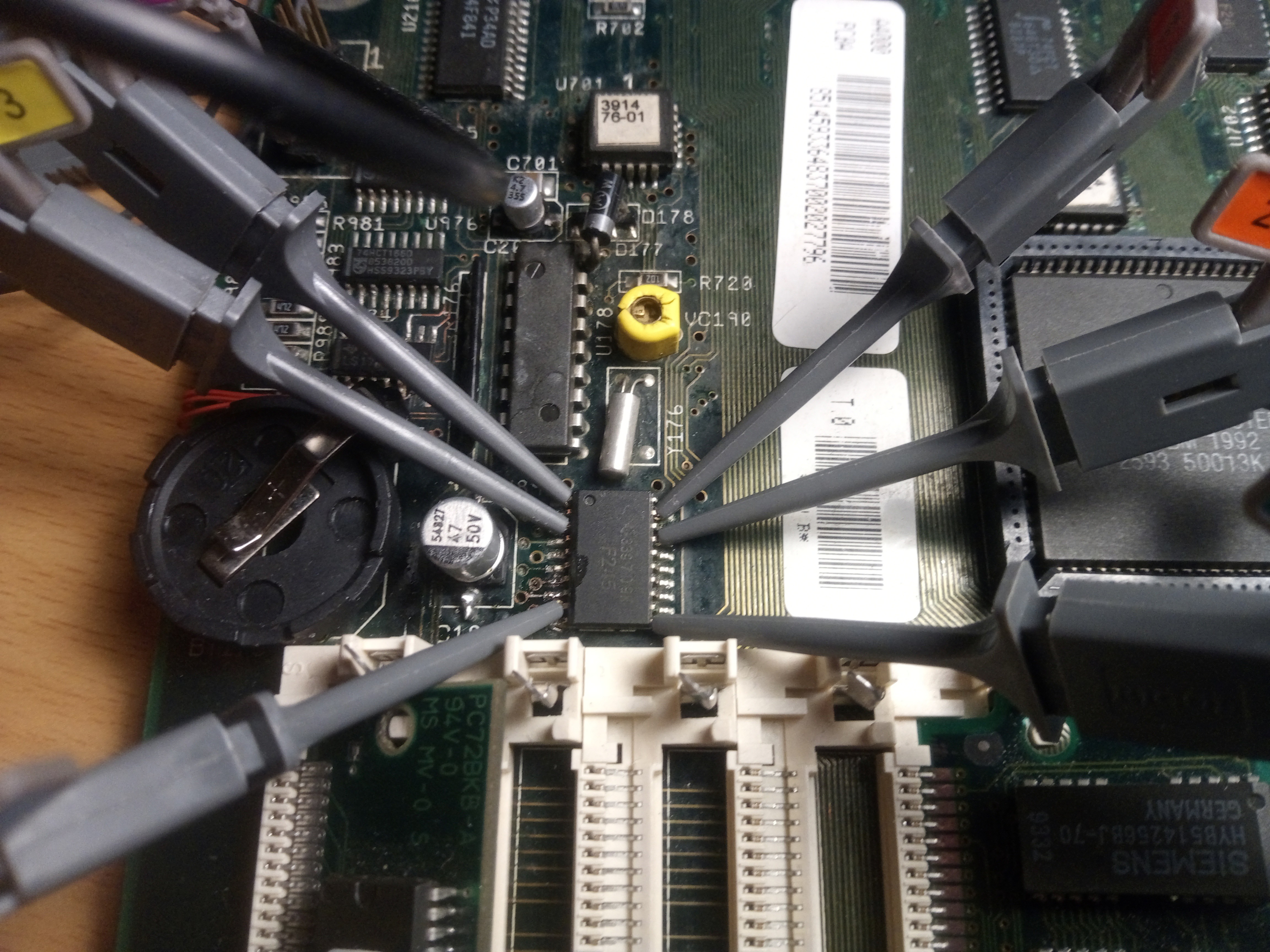
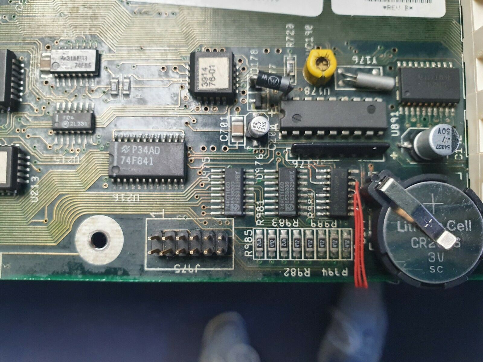
 One hot air session later:
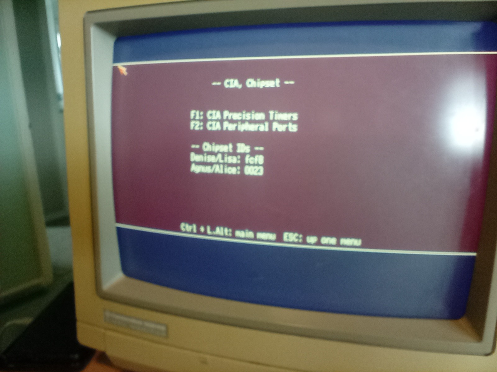
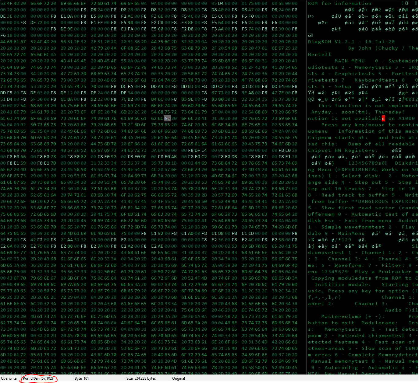
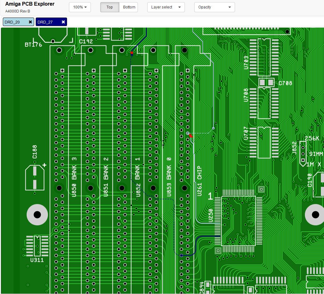
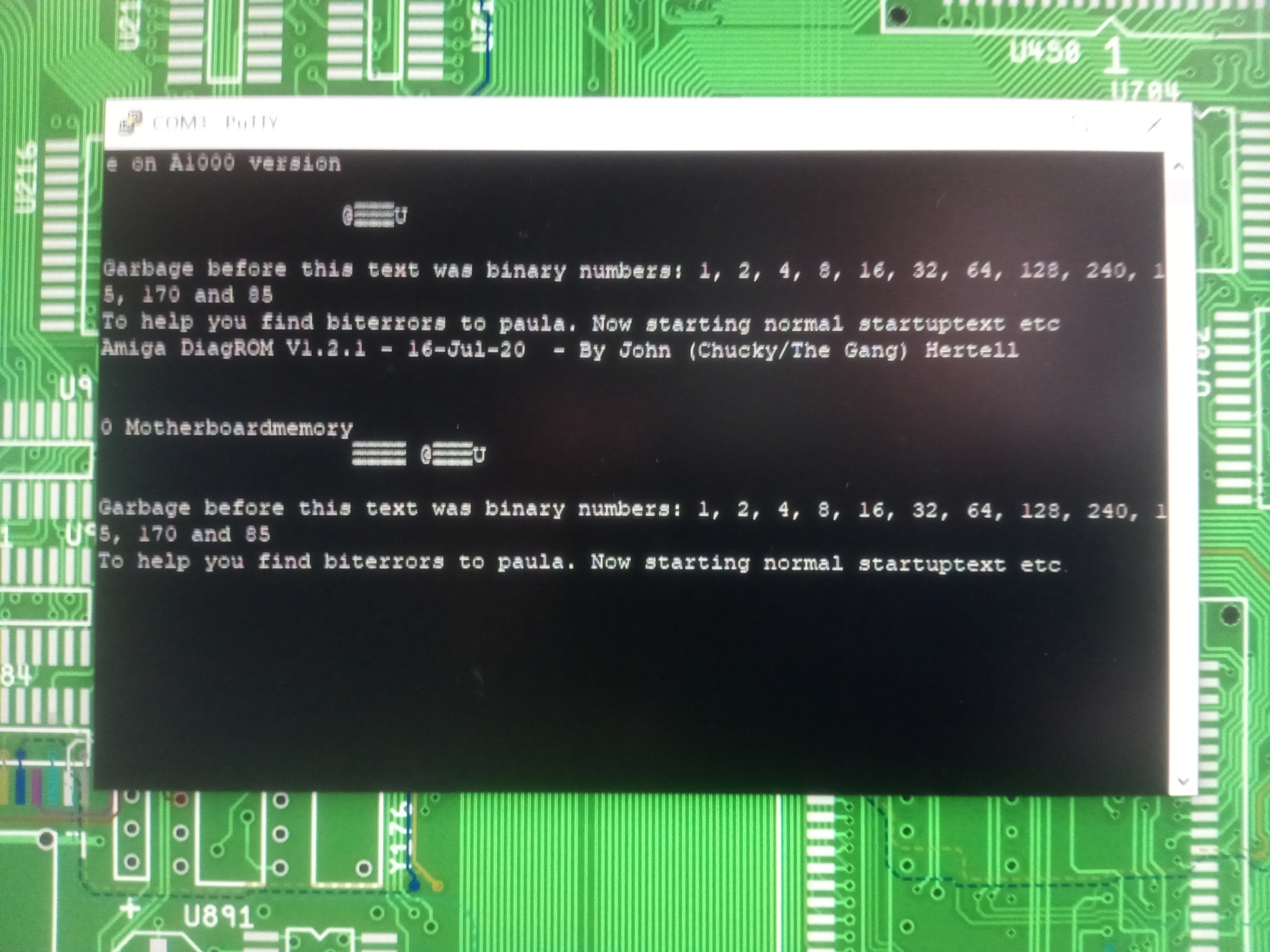
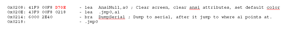 See that address on the first line: (0x)D70E ?... that's remarkably similar to the address 0xDF0E of our 'e on A1000 version' string...
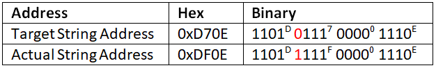
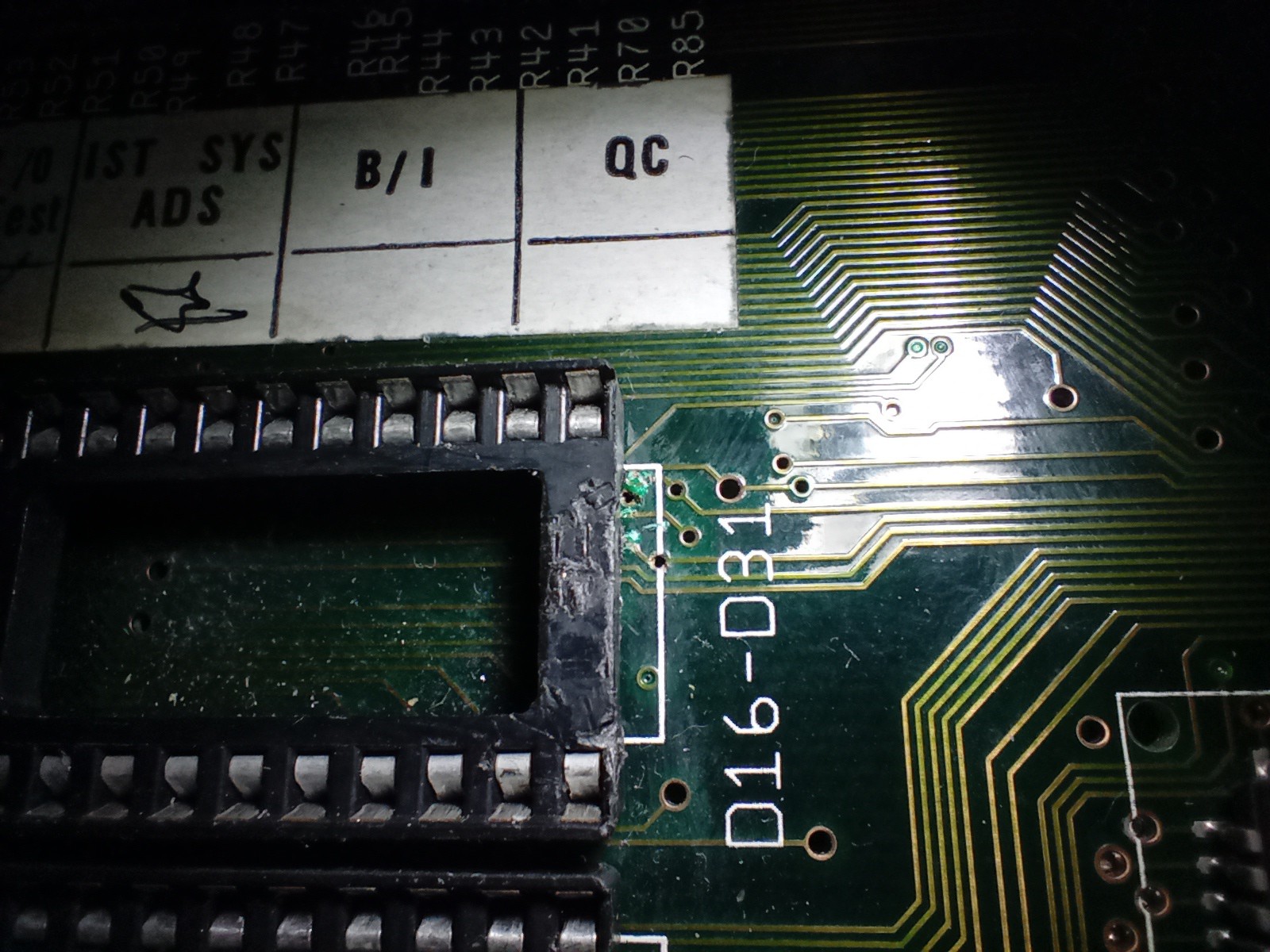
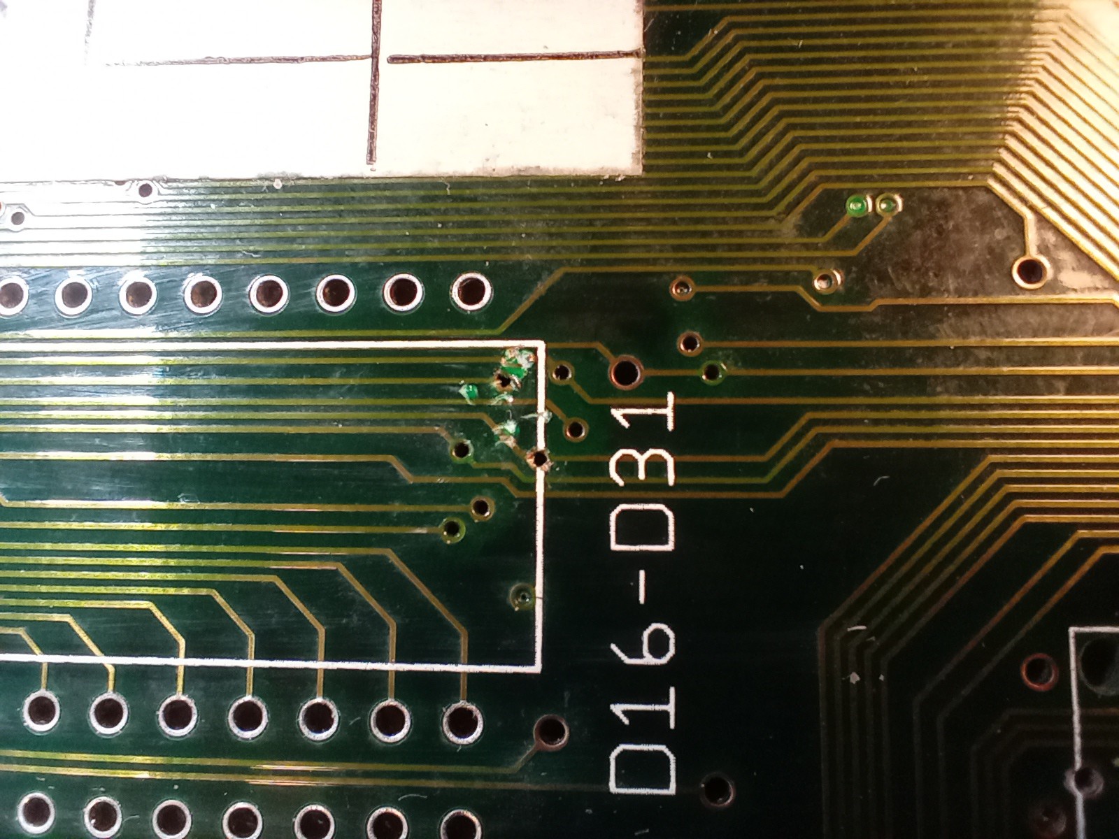
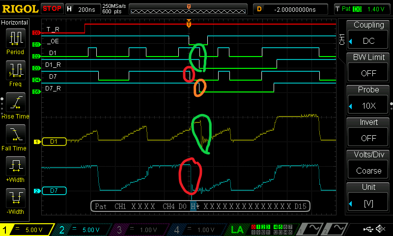
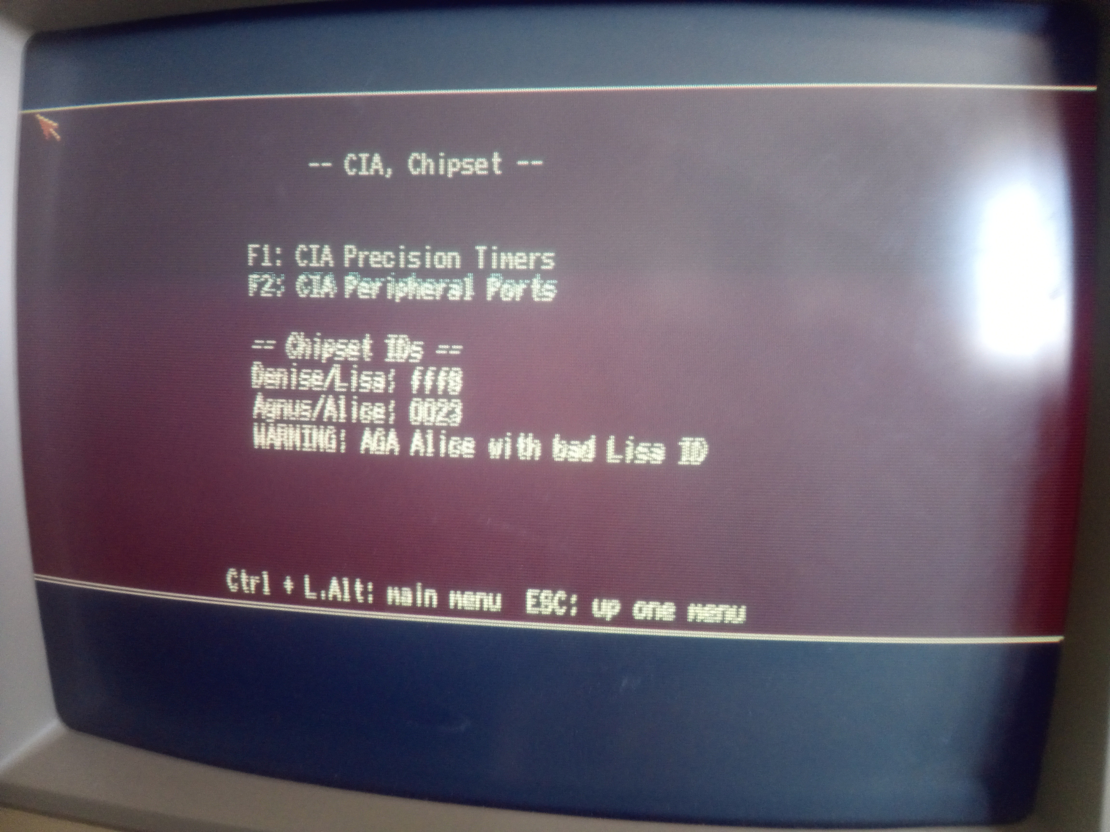
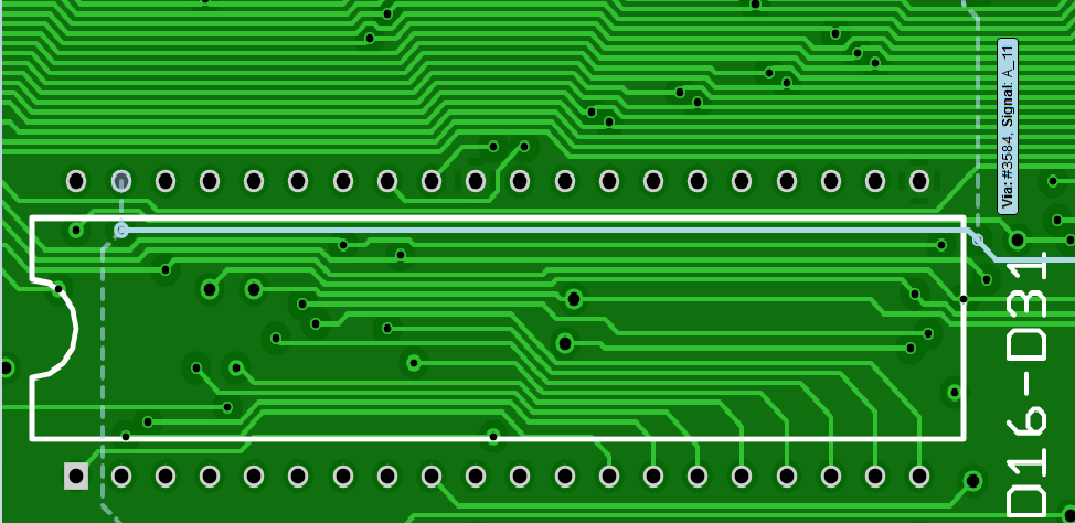 Aha! A_11 !!
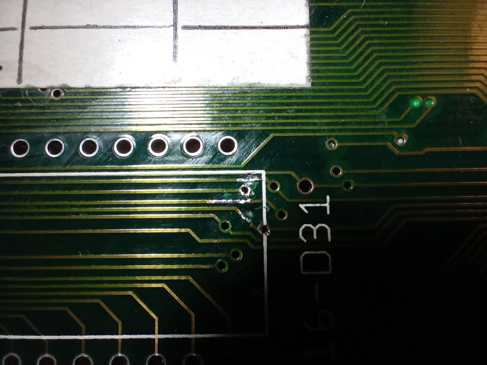


 Eric Hertz
 Maarten Janssen
 Hayden Kroepfl