 shane.snipe
Top 3 struggles I have with robots and how this project solved them.
1) Cost too much. Mostly because of expensive servos and high end processors.
- Designed a cheap driver/sensor board to read the absolute angle of the motor joint and run the motor. Designed a 3D printed connection that use the motors as structural members and use the 3D printed ramps to change the distance from the optical sensor with rotation. Used the worlds most ubiquitous yellow gear motor found in inexpensive projects everywhere. Using extremely common FFC cables to link the legs and the boards for one robot cost 15 dollars and can arrive on your doorstep in 8 days! The boards also have what would normally be the guts of a servo motor, but now are more accessible to the processor which can access the position of the joint at any time.
2) Processor creep. Robots eat IO pins for breakfast.
- Used a double demux in which the PCA9685 board is also controlling the analog demux. In this way I can run 6 motor joints and read their position with only two I2C pins and one analog input. This leaves ~20 other IO pins to do range finding, balance, audio out, I2S audio in and many other functions yet to be added. This can all be run with a $5 ESP32. Lastly, it is expandable to allow 3 additional pairs of arms, legs or wings, whatever you may fancy. This is achieved with just adding a daughter board with the PCA9685 expander and the 74HC demux chip.
3) Wires and batteries make a robot ugly and unstable.
- The last advancement is a unique setup for how to connect the motors and batteries. The legs are connected to the brain board through a double row header so they can easily be exchanged. First hip board with the header has two FFC cables that run down to the Femur and Tibula boards which are common and can connect to the battery. The cables are elegantly threaded though the joints with service loops to allow the legs the full range of motion without risk of the cables being snagged. The batteries, one in each foot to lower the center of gravity, have a separate set of traces that link them in parallel through a BMS in the head board. This allows the motor to be run at 7.4-8.4V and be charged through a 9V adapter plugged into the headboard.
Purpose
Cya was designed to encourage makerspace members to learn about robotics and the tools used to make this Robot. Here are some reasons Cya serves this purpose well.
Designed with maximum availability in mind.
All the electronic components and motors are available on Amazon, mostly with Amazon prime.
Board files are available and 10 bare headboards and 10 sets of populated leg boards can be ordered from JLCPCB for $150 and delivered in around a week. With some better availability on alternate motor drivers and sensors I expect to be able to cut this in half.
There are eight 3D printed components that make up a leg and two legs can be printed on a$259 Sovol S01 printer in one print job. The filament for the one print job costs less than a $2 and finished in less than a day. Another option might but using a 3D printer at one of the main libraries that now offer them.
The rest of the parts are standard hardware like screws and headers.
Everything is attached with through hole soldering or connectors. The only tools needed are a soldering iron and a hex driver.
Everything can be run with Arduino to start with. Micro Python modules are being built out and there is a plan for native C in Doxygen using Expressif libraries. There are example sketches and tutorials for most of the modules in Arduino so we stand on the shoulders of giants and this project leverages the open source efforts of the community. A special shout out to Adafruit and the PCA9685 board that Cya is designed around. https://www.adafruit.com/product/815 Their great documentation spurred the idea and got me going.
Designed to be centered around scalability. Please Choose your own adventure.
Cya is designed around the MH-ET Live ESP32 variant. It leverages all the ESP8266 Wemos shields and great care has been taken to ensure those pins remain available. An example of this is the ability to use the display shield and add a display without adding any other hardware to Cya.
Additional scalability is found in the use of I2C. There is a board to board I2C expander on the top of the brain board which allows for additional sets of legs or anything else you can control with I2C. There also is a I2C header broken out on the brain board if there is a particular sensor you would like to add. There are also four M5 mounting holes to attach what ever else you may design.
I believe you should be able to build a robot the same way you eat an elephant, one chunk at a time. Here are the chunks I imagine that would keep the makerspace member charged and coming back for more.
1) Core build of brain board and legs with power circuitry. (1-2 hours)
2) Add a display and learn to make in display text, robot parameter outputs and pictures.
3) Learn how to record key points of leg positions and play them back to create
unique gaits and teach the robot to walk.
4) Add the ultrasonic sensor and display the distance to an object on the screen.
5) Add sound through the DFPlayer board. Get Cya to make different tones based on the distance to different objects.
6) Add hearing through the I2S microphone. Get Cya to respond to claps to move from key point to key point.
7) Add a wake up word to start the voice recognition track.
8) Add the Gyro and load the program that allows the balancing of the hip motor with the position of the alternate leg based on the calculated center off gravity.
Now that the base robot is complete and some of the functionality it is time to choose your own adventure. Here are some suggestions
1) Learn to program all the above modules in Micro Python.
2) Make an add on board in Easy EDA and order it. Connect it to the expander header on the top of the brain board.
3) Add that second set of legs. Maybe a third. The same leg design can be used by just simplifying the brain board to the BMS, power regulators, PCA9685 and the Demux.
4) Time for a tail! There is an extra PWM slot on the PCA9685 board. Connect it to a servo and design and 3D print a tail in Onshape.
5) Start to introduce some professional tools. Solidworks is coming out with an educational license. Use this to redesign the feet to be more appropriate of four or six legged creature.
It is really endless but you get the picture.
Hardware Description and Rationale of Design Decisions
Legs
The reason why this robot can function is the pairing of the optical sensor with the reflective surface on the inside of the 3D printed leg. Here is a view of the ramp that looks like a spiral staircase inside the leg.

As the joint turns the distance between the face of the ramp and the light sensor varies proportionally. If the sensor voltage output changed linearly with distance, you could have a nice sensor.
There are 4 lever that I found to pull to get to the goldilocks area of linear response. The first is the resistor value for the emitter LED. I started with the value used by Sparkfun on their line followers using the QRE1113GR. Changing this changes the distance away the sensor needs to to sense things. I left the 220 ohm resistor that they used. If I changed it to 330 I might have been able to have gotten a little close to the surface.
The second lever is the resistor on the detector. This one is critical and after experimenting I picked 47K. The way I see it is the higher the value the longer flatter the curve below.
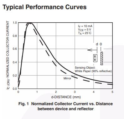
It shows current on the vertical axis but I think this is also a proxy for voltage. This shows the current starts to
come down after 1mm. I wanted to use the nice linear range at the beginning.
As you can see on the chart, it talks about a mirror or a white paper. My first tries were in white. I struggled to get good data as it was super sensitive to the incandescent light in the room. I spent a lot of time trying to make the part thicker or putting a second color behind it to limit the light coming in. Eventually I figured out that a layer of black duct tape does the job.
Well the white PLA reflected very well but changed very little with distance. I tried gray, but then it reflected very little and showed very low values. I finally tried yellow and it seems to be a very nice middle ground.
I had thought that the more distance change on my ramp the better sensor would be. However, it s non linear and there is very little change from 1 - 5 mm away. However, on a scale of 0-4095 for 0-3.3V, I get 730 ticks in a fairly linear fashion from 5.9-7.8mm from the light. When I used ramp that went from 2.6mm away to 6.4mm it was much more like a hockey stick with only the last half mm showing a decent response.
So, for now, with Yellow, 6-8mm seems to be a nice range. To get 730 ticks over 180 degrees is fabulous. I will map it to 1-100 and it will be more than sufficient for my purposes.
The other interesting thing to note is the printer prints in 0.05 or 0.1mm layers. So the print actually looks like a staircase. However, even with the steps, I could not tell the difference. The steps seem to average the reflected light and it seems continuous and each movement shows some change.
I am thrilled with my results on the encoder but this project has not been all roses. As you can see in the logs, I started out with a concept of putting surface mounted boards on a flex. What I really needed to do was to have all the components directly soldered to a rigid flex. However, I am using the PCB assembly service from JLCPCB and they do not offer flexes or rigid flexes. I bought three rounds of flexes from PCBway but had struggles with reliability every time. It was difficult to solder board to the flex and the gold pads delaminated pretty easily. It was quite demoralizing to have a flex that you spent an hour soldering up break as you assemble it in to the robot. There might have been a solution here but I was running out of time and money to find it.
The second unique design feature is the shape of the hip. To have 2 sensors in this area, routing the FFC though the middle and have a change of axis took some noodling but keeping my eyes on the prize, I was able to figure out a way to do it. The key was the separate shaft adapters, shown in blue below, to allow the clamshell design to come together.

I will change the distance to the sensor to 6-8mm for both of these joints and that portion will be done. The other parts that could be improved is the range of motion in the second joint is only about 120 degres. 180 would have been nice to allow Cya to sit up fully.
Along the lines of range of motion, this joint structure was conceived while I was still trying to make a quadruped. As a biped, I am not sure I can turn with these joints. I think I would need to rotate the joints or feet. I can side step or walk backwards but I can not turn to look at something. It bother's me but I think it is something to worry about after I can stand up and walk around a bit first.
Standing up
Playing with the joints, I found a sequence that would allow the robot to stand up. However, the last sequence is to bring the legs together from a split position. I tried to make it happen but it did not have the torque to do this at 4.2V to the motors. This is one of the main reasons I decided to change to connect the batteries in series very late in the game. In fact, that was decided last weekend, two weeks before the close of the contest. It mandated a full re-spin of all the boards. However, the flex circuits were so delicate, it was necessary anyways so I decided to go big and change to the FFC connections.
Walking
So far I have got the motors to move to a changing mapped % of angle position. As I adjust the ramps to make them more linear, this will only get better. I got it to move CW or CCW based on its absolute position and the knowledge of its target. However, I just shut off the motor when it reached the target and it often overshot. I am thinking of implementing a proportional factor so that the motor slows down as it gets closer to the target. With the voltage being low, there was very little range to play with. There are 4096 counts for the PWM but the motors only moved in the last 500 or 1000 ticks. With 8V, I will have a lot more range to play with. Hopefully this will also result in finding a PWM range where the motors hold, even if there is enough weight to move the motor if the motors were not on. I think this will end up being a part of the proportional control.
Now back to walking. I am thinking of walking as a series of key points. I can see the counts on the screen so the first version will be reading the counts of a few positions and programming it to move from position to position. The next iteration should be to read a file with positions. It would be cool to have one robot be able to teleoperate another. Another goal is to have the user move the robot through a series of key points and press the switch each time a point should be captured. Then it the robot should be able to replay the sequence.
Balancing
So far, I have been thinking of the programmer taking care of the balance of the robot by making the right sequence of steps. Well it would be cool to use the accelerometer to do some of that. I have not worked out the algorithms to do this yet but it is churning in the background of my mind. I have some things I want to try and am looking forward to this stage. It will make Cya look much more lifelike.
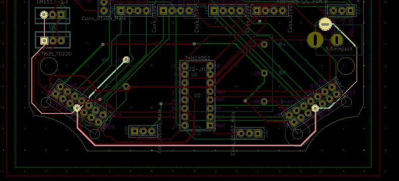
Brain board
The brain board was designed in Kicad and the Kicad project and Gerbers can be found in the project files. The component can be placed on either side of the board but both sides definitely need to be used. The board may be more compact without the use of headers but the convenience of being able to swap out modules keeps me coming back to them. It is so helpful in debugging.
I will be listing components and links. If you can support Adafruit or DFRobot and the components are available I suggest you purchase from them. I will leave links to their documentation as well. However, as accessibility is a key tenet of this project, I will also leave a link to an Amazon component. There is risk in purchasing from Amazon and Ali Express. There is a possibility that the components are not genuine and you may spend an afternoon scratching your head on why it does not quite work, but that may be part of the hobbyist's experience.
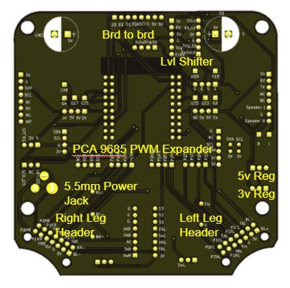
Here is an annotated picture of the board, some links on the components and my design rational.
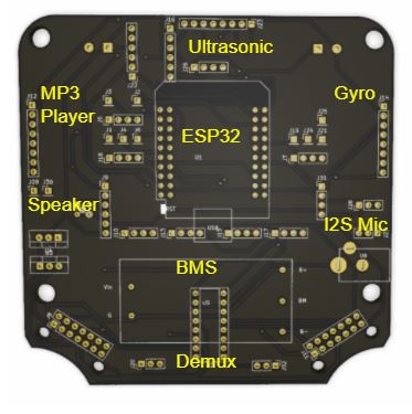
Ultrasonic Sensor
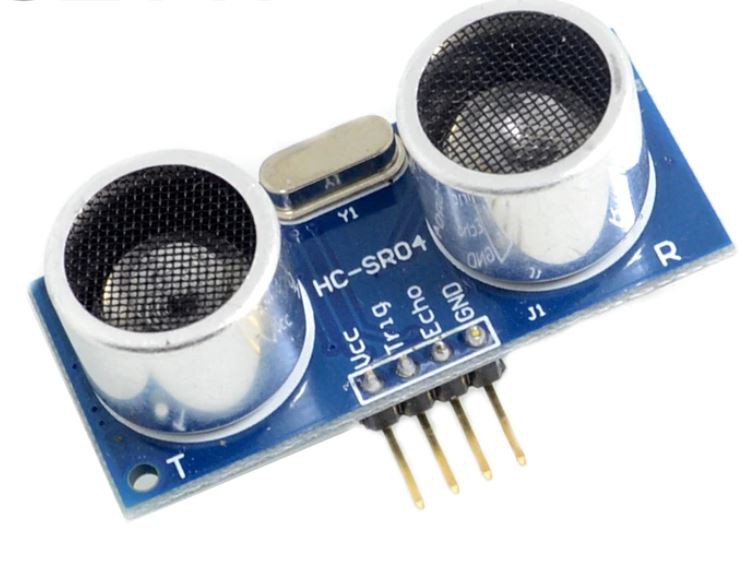
https://www.adafruit.com/product/3942
I almost opted for the 3V version of this as it would have saved one level shifter. However, this is the most common sensor in everyone junk box. I want the parts to be accessible and the libraries to be common so I bit the bullet and specified the 5V version and put the level shifter in. I definitely needed the level shifter for my next component so it really not an issue.
Amazon
Amazon Cost adder 10 for $12 or $1.20 Sum $1.20
Ali Express cost adder $9.20 for 10 or $0.92 each Sum $0.92
MP3 Player
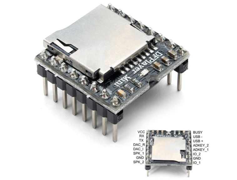
This is one where genuine parts may really make a difference. I read a lot of the Amazon reviews and there were a lot of complaints about the knock off versions. I am starting with the one from DFRobot but will try others and will update as I go along. DF Robot did do a good job on the documentation so kudos to them for that. There is another name for this model that is MP3-TF-16P. I am not sure if they are equivalent or not. I tried to error on the side of caution and link to the ones that say DFPlayer.
Amazon Cost Adder 10 for $25.98 or $2.60 Sum $3.80
Ali Express $11.82 or $1.18 Sum $2.10
ESP32
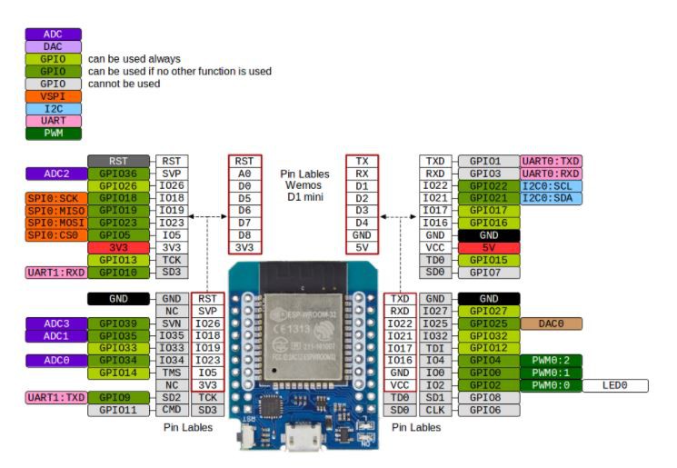
Choosing to use the ESP32 was easy but which one to choose was a more difficult decision. However, to promote expandability, I think the MH-ET version really provides the most compact and cost effective solution. The inner pins in white above are the same as the ESP8266 Wemos D1 Mini and I spent years making designs with that one. There are so many modules that automatically expand my robot like the Display I show next so I could not give it up.
The downside is that some of the modules have a substandard 3.3V regulator and it does not have enough power to run WIFI, never mind power some other 3.3V components on the board. I have added my own 3.3V regulator. I am a little nervous as I am powering both the 5V and 3.3V lines with regulators where I usually either just power one or the other. We will see how it works out.
Amazon Cost Adder 10 for $70 or $7 Sum 10.80
Ali express $5.20 Sum $7.25
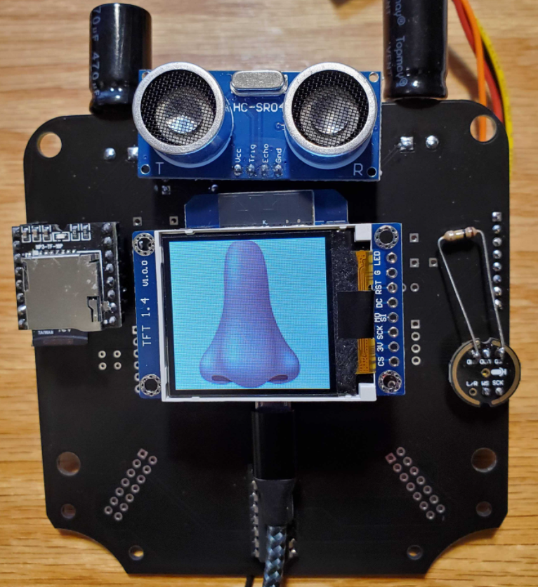
1.4 In TFT Display
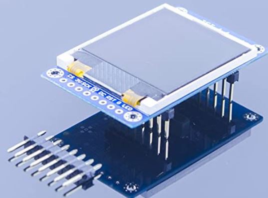
When I got this working it one hundred times validated my choice of processor above. The ability to have display give me real time feedback on my encoder positions has made playing with the robot so much more fun. I just plugged it into the headers on the ESP and I have real time access to the outputs of my sensors.
Amazon Cost adder Presently Not available
Well that is disappointing. I really was enjoying using this display. I checked on Ali Express and could not find it either. Maybe it is a casualty of the chip shortage. Check out the beauty below that Doug posted.
For now, for the sake of accessibility, I will substitute in the tiny OLED model .
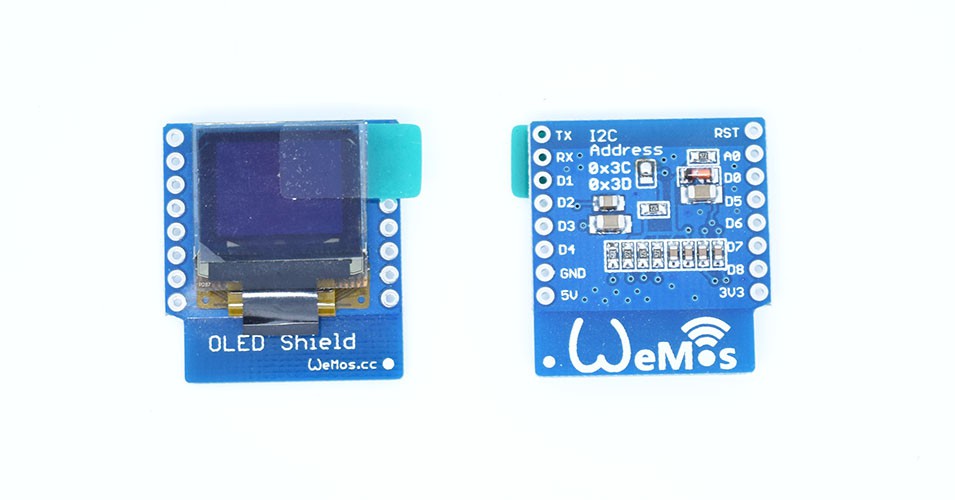
I may need to make an adapter board so we have a better options for TFT displays that plug right in. Alternately I could pull out pins on the board to connect it directly.
Amazon Cost Adder $7.99 Sum 18.79
Ali Express 10 for $20 or $2.00 Sum $9.25
Gyro
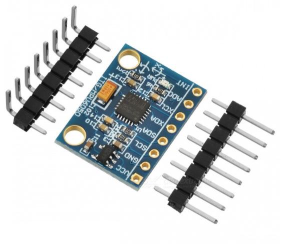
This is a questionable choice as the company that made this chip has been bought out and has replaced it with new versions. However, it is everywhere and you have to go with what you know, especially if you want to be accessible.
Amazon cost adder 10 for $16.99 or $1.70 Sum $20.49
Ali Express 10 for $15.44 or $1.54 for 1 Sum $10.04
Speaker
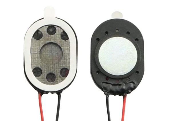
The design consideration here are that it should be 8 ohms, inexpensive and fairly light. These ones are for tablets so they should be loud enough and adhesive should allow it to be stuck behind some through holes on the board. Having the wires pre-soldered is also a bonus.
Amazon cost adder 4 for $6.99 or $1.75 each Sum $22.25
Ali Express $6.63 for 10 or $0.66 each Sum $10.70
BMS - Battery Management System
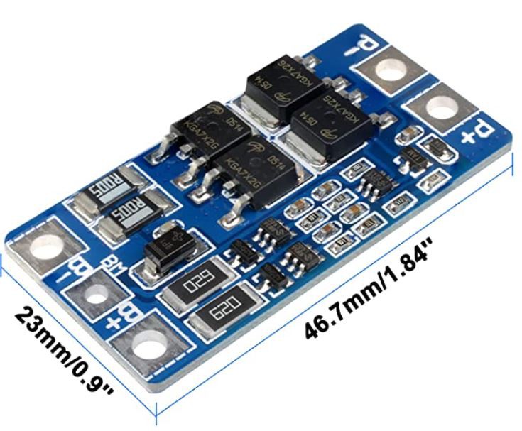
A BMS protects the Lipo batteries from becoming over charged or over depleted. It allows a single input to charge the device. Again striving for accessibility, this one was available and the only one I could find with through hole connections. Calling them through hole is a stretch as the holes are 3MM in diameter so the header pins are going to swim in the holes but if I bias it to one side and bend the pins a bit I should be able make it work. This is a huge board but because it is floating above the demux it will work. Best of all, it allows 7.2-8.4 V to the motors which are needed to make Cya pop up. The circuit works with both leads coming out of the left leg up double traces on the FFC. Then the negative goes to the BM center tap and the Positve goes to B+. Feed that same Negative into the Positive side of the right leg and bring the negative back to B- and I have my series circuit. P+ goes to the BV (Battery voltage) to run back down the legs and run the motors and P- becomes the ground for the entire Robot. The P+ or Vin goes to the 3.3V and 5.0 regulators and the charging connector. This way the robot can function during charging. Here is the net on the board.
Again this BMS is specified for 18650 batteries which have more capacity than the ones I chose but it was the only accessible one I could find that had through holes.
Amazon Cost Adder $12.99 for 5 or $2.6 each. Sum $24.85
Ali Express $15.04 for 10 or $1.50 Each Sum $13.20
Demux
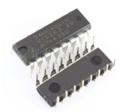
Any time you see a 74 at the start of a chip you know it is old. However, this one really helps out. The 74HC4051N allows me to scroll through the analog inputs from the light sensor and switches. I was concerned that it may not be fast enough but I have not seen any issues on this front. Additionally, I have the PWM board triggering the 3 digital selection inputs to further save IO. This is why I call it a double demux. With 1 analog input and 1 I2C port which is used of elsewhere anyways, control all the motors and ready the analog inputs. It allows me to have one ESP32 be able to control 2-4 pairs of legs, reading up to 48 analog inputs and controlling up to 24 motors. This may be the oldest trick in the book but when I thought of it I was tickled.
Amazon Cost adder $8.39 for 10 or $0.84 each. Sum $25.61
Ali Express $2.51 for 10 or $0.25 each Sum $14.45
Back side
Again going though the parts on the back side top to bottom, left to right.
Board to Board Connector
There are a bunch of headers needed for this project and most of the modules do not include both male and female headers so I will include the cost here. This port is the key to the expandability of this project. The intention was to be able to run 3 more PWM boards and Demuxs from the original ESP. So I include 5 and 3.3V, an I2C connection, and the remaining 3 easily accessible ADC connections on the ESP. The ESP has 4 Analog connections that can be used while WIFI is on. I have not used WIFI yet but I do not want to be limited to not using it. For a second set of legs for a quadruped, the board would just have the PWM expander, the demux and the BMS. Then it could use exactly the same legs. This project actually started as a quadruped but when I realized how it could be modular, I made my MVP (Minimal viable product) the biped and left the rest for expansion. I am stoked to see what someone can do with 4 sets of legs!
I have broken out the following pins.
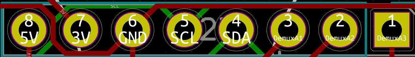
Here is the header kit that will be used all over the robot. I included 2 for 10 bots. I am not sure exactly how many are needed but it certain that one kit will not suffice for 10 bots. In any case, a makerspace or electrics classroom is always in need of these so stock up!
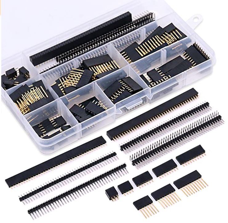
Amazon Costs Adder $27.78 for 10 or $2.78 each Sum $28.39
Ali Express 3 x 10 pcs x $1.20 $3.60 for 10 or $0.36 each Sum $14.77
Add long 10 pin female headers 4 x 10 x $1.90 / 10 $0.76 Sum $15.43
Level Shifter
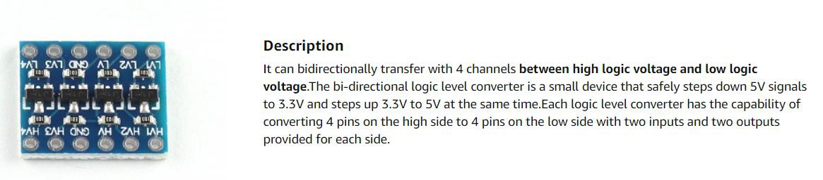
This is my goto solution for 3.3 to 5V transitions. We have two transitions needed on the robot. The ESP can only accept 3.3V inputs and we are running the Ultrasonic and DFPlayer at 5V. This could be solved with resistors or diodes on the inputs to the ESP but the level shifter seems like a cleaner solution and it really is not that expensive.
Amazon Cost Adder $6.95 for 10 or $0.70 Sum $$29.59
Ali Express $2.91 for 10 or $0.29 Sum $15.72
PCA9685 PWM Expander
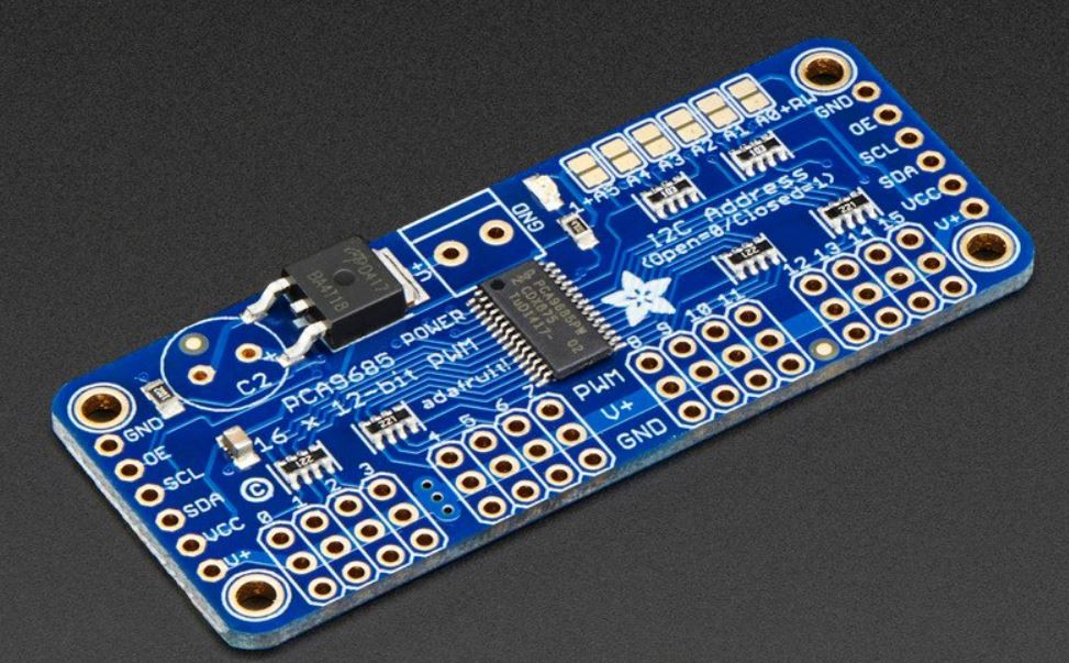
This is the star for the show and what makes the project possible. I bought a couple from Adafruit more than 5 years ago and have dreamed about the possibilities ever since. My dreams are finally coming true. Not that only the PWM pins and one driver side are populated. I have plenty of bulk capacitance on the bot with my Capacitears on top so I have not populated the capacitor. Besides, I am only driving signals with this board, not motors. The motor power comes from the BMS directly. I would love to have LED's on each PWM pin to know if signals are going out and the board is a little large. Maybe some day I will integrate it in to the head board but for now, it is what makes it all work. If you can support the good work Adafruit does, pick it up there with something else cool that the do. They have some motors that are similar to the motors I use this project with metal gears that might be a good addition.
Amazon $6.95 SUM $32.67
Ali Express $29.53 for 10 or $2.95 $18.67
5.5mm Power Jack
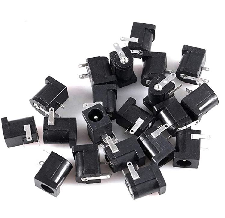
This is the first time I have actually designed one of these into the board and I learn a lot doing it. The Positive on this one is the center tap that comes out the back of the jack. Being able to use a 9V wallwart to charge the batteries is great and adds to the finish and frankly safety of the product. I believe the 5.5x2.1mm type is the most common and that is what I chose.
Amazon 20 pcs at $5.69 $0.57 per pcs when converting to a 10 pcs build. Sum $33.24
Ali Express $2.31 for 10 or $0.23 each Sum $18.90
5V Regulator

The only thing running at 5V that pulls significant current is the DFPlayer and the 1.5A capacity should be more than enough for that. I did not attach the heat sink to the board because again, there will not be much current running through this part.
Amazon $4.99 for 10 or $0.50 each Sum $33.74
Ali Express $1.91 for 10 $0.19 Sum $19.09
3.3V Regulator
For the 3.3V there is even less current. However, I previously had the 3.3V regulator on the Esp sourcing all the 3.3V power. Some of these units have regular with a very small current limit so I decide to put in regulators for both 5 and 3.3V and make both inputs into the ESP. Used the LM1117T-3.3.
Amazon $6.99 for 12. $0.70 at 10 pcs pricing. Sum $34.44
Ali Express $3 for 10 or $0.30 Sum $19.39
CapacitEars
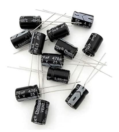
Each of the modules have capacitor so I did not add an smaller values but it made sense to concentrate the 3.3V and 5.0V bulk capacitor requirements and make some nice big ears or horns. One of the people from my makerspace called them CapacitEars and it kind of stuck.
Amazon $6.99 for 20 pcs or $0.70 per 2. Sum $35.14
Ali Express $3.67 for 20 or $0.37 for 2 Sum $19.76
Switch
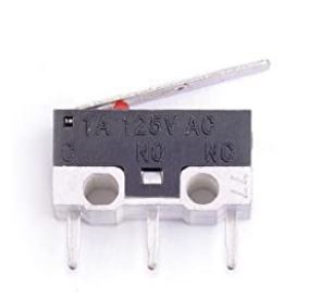
I had the switches in the feet but I did not get the point of using them yet. I did want some switches in the head for user input so I moved them up there. The idea is you would move a leg to a desired point and then press the switch to have the robot remember the position of the leg. Cycle it though multiple positions and then let it play. If I want a switch in the feet again, I can always run wires down from here. Actually, it will only need to be one wire because there is a 3.3V pin header in each foot that is open.
Amazon 25 pcs for $6.99 or $0.70 per robot. Sum $35.84
Ali Express $3.72 for 20 or $0.37 Sum $20.11
Motors
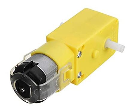
Since this project is also built around being able to use these cheap motors like servo, I probably should have put this one first. There are two version of this motor, one with a gear ratio that is 1:48 and one that is 1:120. I tried really hard to use the 1:48 but with the 4.2V I was getting previously, there was no way. I have now increased the voltage to around 8V and there is a chance that they can be used again. For accessibility I want to use them but the 1:120 are so much better. For now I will error on the side of caution and only link to the 1:120 but it removes the instant gratification chance of getting them from Amazon Prime. Maybe this project will drive there resurgence. I know I have already bought out all the sources I could find.
I have had prime options come up previous at less than $2.00 each
Amazon $12.94 for 4 or $19.41 for 6 Sum $55.25
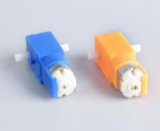
Note: This Ali Express motor is slightly different. Instead of the flexible strap gearbox traps the end. This actually works better as it allows the pcb to sit flat on the motor. It is no longer the yellow motor but...the price is right and so is the gear ratio.
Ali Express $66.21 with shipping for 60 motors or $6.62 for 6 motors Sum $26.73
M3 Bolts
Also need bolts to put it together. It requires 8 pcs of M3x30 and 2 pcs of M3x40.
To get 10 bots, getting 3 boxes of 50, plus and assortment plus a bag of 100 nuts would
complete the requirement.
Amazon 3 x 50 pcs $18.78 or 1.88 per bot. Sum 57.13
Amazon 1 multpack $8.98 or $0.90 per bot. Sum 58.03
Amazon M3 Nuts 200 pcs $8.24 or $0.82 per bot. Sum $58.85
Ali Express M3x30 x 200 pcs 13.27 or $1.33 per bot Sum $28.06
Ali Express M3x 40 x 50 pcs $4.65 or about $0.47 per bot. Sum $28.53
Ali Express M3 square nuts 4 x $0.87 $3.48 or $0.35 per bot Sum $28.88