 shane.snipe
Well it was cool to play with it when it was assembled. The flex integration looked great but there was one tiny problem. Even though I verified all the connections before assembly, after assembly I only got signals from one joint and only got one joint to move in one direction.
Daylight
 That daylight you see under the pins is not doing me any favors at all. The cause is two fold. The first is the flex vendor changed from through hole to pads when I requested the adhesive on the back. The first round of flexes had through holes and I did not change the pads at all in between builds. I think the adhesive is on from the beginning so I can not have adhesive and plated through holes. The second is that there is a tab on the motor gearbox housing that holds the strap the holds the motor into the gearbox. That tab is a little proud of the part the PCB is on so it is causing an uneven surface which bends the flex and breaks the traces.
I think I can deal with the bump by making a 3D printed backer that goes under the flex. I can then use the adhesive to laminate it to the backer and protect the flex. I will have to a adjust the bosses on the hip 3D printed plastic holders but i could bias it to the side by a millimeter to get by.
Side view
 I was hoping the flex would be flexible enough to do its job but as soon as you mount components to a flex, it needs to be rigid or you risk delamination.
Which brings me to to the redesign of the flex which I planned to ship today. The trade offs seem to be through holes versus adhesive. I use the adhesive to anchor the flex on the side of the motors and love the way it is sitting. Full range of movement and no binding.
 So I want to keep the adhesive. Also to be honest, the pads actually worked out out better than through holes for mounting. The sensor boards go on like butter and even the completely blind motor driver outputs have worked flawlessly. I just drop some solder in the holes on the board and add some heat the the pads under the board get connected. It felt like a minor miracle. I would love to have the motor connection through holes back. At first I tried to pierce them and create my own through holes but the pads come off pretty easily. I gave up and soldered wires. There is no stress on them so it is not bad. Maybe I can make some non plated through holes next to the pads so the motor terminals can come through and I can fold them over to solder. I want this to come together as seamlessly as possible and every time I add a wire, it feels like another couple of minutes in assembly.
The other issues that need to be fixed on the flex have to do with the foot area. When I stopped trying to cram the switch and battery board in the foot area I could at least assembly them. However, I think the switch will be super useful. Quadrupeds usually have a switch in the foot to let the robot know to stop trying to push through the floor. With this purpose in mind, I suppose it should be on the heel. I put it in the center of the foot and my design had a flexible printed cover so the switch lever would not catch on things but I am not sure if that is sufficient. The other way to do it is to have the full foot on a spring and when the spring is compressed, the switch is triggered. This makes it so the position of the switch is not an issue. I guess there is also a possibility of a of a hybrid of the two where a lever or plunger is depressed and it activates the switch. I want the switch to be assembled as easily as possible without the switch making it harder to walk.
After much deliberation, I decide to put the battery board between the sensor board and the motor terminals on the tibula motor. I will bring the switch up so it can be mounted on the heel and tuck half way under the motor. The center pole will be in the center of the flex and I will design the holder and plunger later. This saves a half inch of flex which is money. I will make one tap 3.3V and the other the signal line. I have it as signal and ground now but that only works when you have a pullup for the signal line. With the demux, I cannot connect it to a pullup. Center tap should be 0.150" from the edge of the flex and 0.080" from the bottom. The battery board first two pads will be 0.100" in from the edge and 0.050" up from the silk screen between the battery contacts.
For the battery contact, I will replace them with NPTH and move the pads in board. I will replace them with square headers like the switch and battery board pins. Rinse and repeat for the other 2 motors. Lastly I need to change the holes for the hip sensor board to move them outboard by about 0.040".
OK, now I just have to do it. I will post the files when I am done.
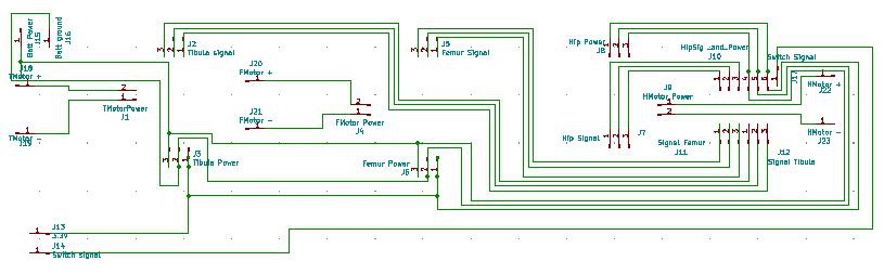
Here is the schematic. I do understand the schematic does not have to look like the circuit. I just keeps me centered.
Discussions
Become a Hackaday.io Member
Create an account to leave a comment. Already have an account? Log In.