 shane.snipe
Maybe I should first target moving the joints with a repeatable motion.
To get there here are the logical progressions.
Confirm the correct voltage is running through the system.
I made some big changes with regards to voltage management. The batteries are connected in series to the BMS that is on the main board. Previously I had a battery charger on each leg which pumped the battery voltage to 5V. This round with the batteries in series, 8.4V is regulated down to 5V and 3.3V to run the lower power processor and sensors. The native 6.4 - 8.4 Li-PO battery voltage is applied directly to the motor drivers for minimum losses and maximum power. The concerns I will have to investigate are:
a) How much does the battery voltage degradation affect the motors?
b) Is it going to be important to monitor this voltage and how can I do it? One idea might be to connect the switches to a parallel circuit to the main battery voltage and have them normally closed.
c) I am sending regulated 3.3V and regulated 5.0V into the ESP. I have only done one or the other in the past and I am not sure if I am going to blow up the regulator on the board. I read that the regulator on the board does not have enough current capacity to allow the ESP to run WIFI which is why I am running 3.3V as well as the 5.0V but this makes two 3.3V sources to the same power input to the ESP. For now, I will hook it up and hope for the best. If my ESPs start blowing up, I will remove the 3.3V pin on the module.
Hardware Debug
1) Get all the power components in place.
BMS - Check
Leg headers on board - Check
Leg headers on hip board - Check
FFC to leg boards - Check
Connect batteries to Tibia board.
(I just realized I named by lower joint as amalgamation of the Fibula and the Tibia. I called it a Tibula. I will go back to Tibia)

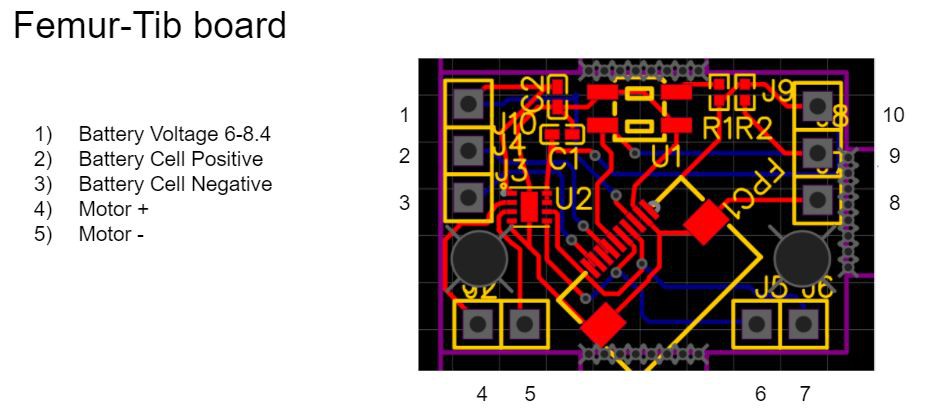
I need to but more silkscreen labels on the board next time. To help with understanding, I made a pdf which all the pin definitions for the legs. I remembered one key point. This robot will only work with B type FFCs where one end has the exposed pins up and the other has the exposed pins down. It essentially transposes the pins in the cable. I designed for it, forgot about it and rediscovered it in my QC of the boards upon receipt. Now that the world is straight and I know which pins to connect the battery to, I can go about confirming the power layout is going to work. Here is the layout. Pin 2 is Battery + and Pin 3 is Battery -.
2) Once power is measuring good, add the ESP and make it blink.
3) Add the screen.
4) Add the PWM board.
5) Read some sensors.
6) Move some motors.
Discussions
Become a Hackaday.io Member
Create an account to leave a comment. Already have an account? Log In.