Max Schnorpfeil
-
Zener-Tester / LED-Tester Update: Chip shortage
08/20/2021 at 06:35 • 0 commentsChip shortage is hitting hard...
I've seen that the AP3015 of the first boosting stage (battery voltage -> 5V) was not available anymore.
I updated the schematic and board of the Zener-Tester / LED-Tester.
Replacing the boost converter with the Xinluda XB61040. It's pin compatible and even a bit cheaper.
Now, everything but the ADC (ADS1115) can be assembled by JLCPCB. (Just order the ADS1115 from LCSC and solder this chip by hand)
-
Zener-Tester / LED-Tester Presentation
08/10/2021 at 06:54 • 0 comments -
Zener-Tester / LED-Tester PCB ready
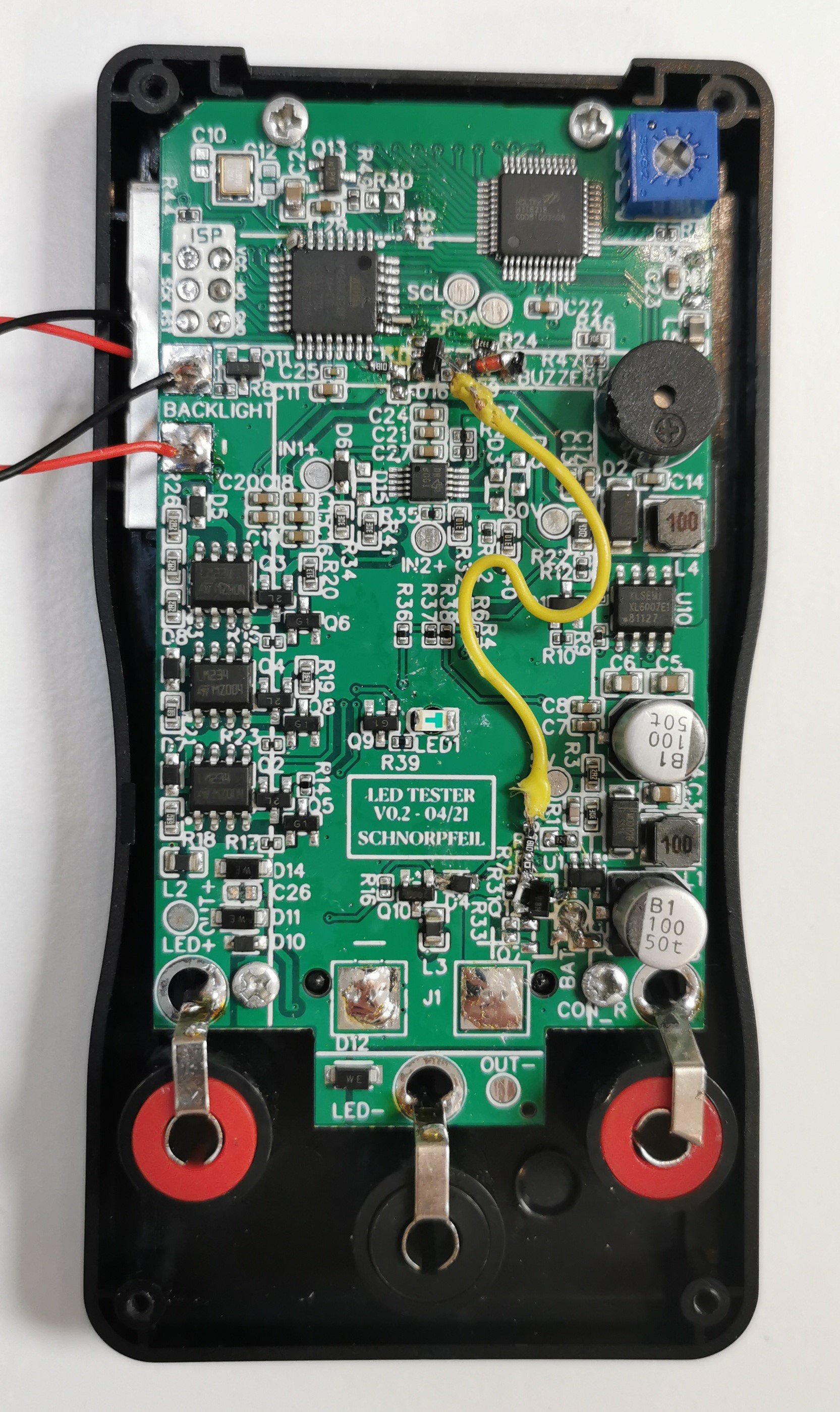
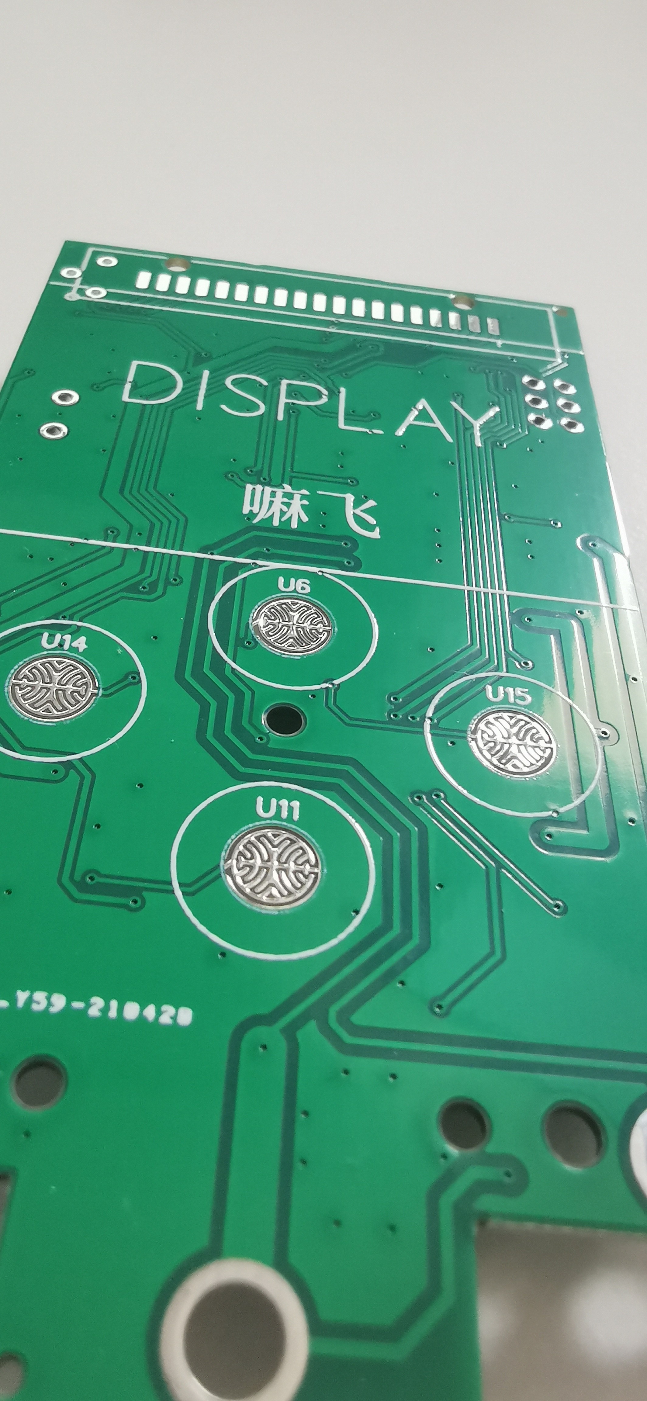
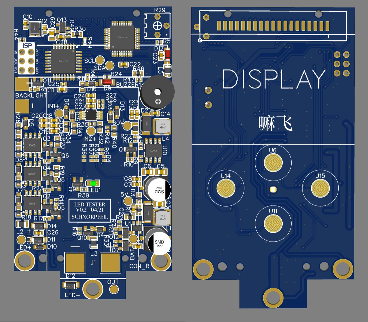
08/08/2021 at 20:23 • 0 commentsPCB's are ready.
Placement of pads and buttons is perfect.
Center LED has to be soldered by hand as it is placed top side down, looking through the PCB.
Detected a problem of the MOSFET latch-on circuit, which is triggered by the lower button (solved by bodge wire). -> updated in the EasyEDA project.
![]()
![]()
Next stop: Programming
-
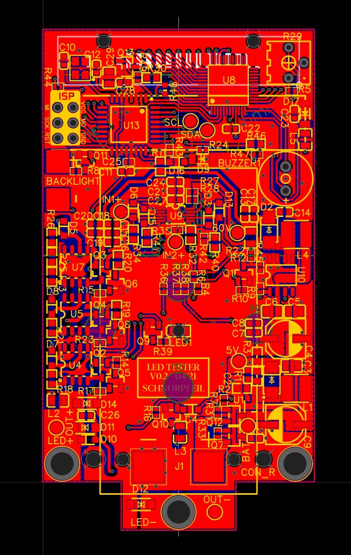
Zener-Tester / LED-Tester Layout
08/03/2021 at 15:51 • 0 comments -
Zener-Tester / LED-Tester Schematic
08/03/2021 at 07:00 • 0 commentsAfter the Template has been finished, the logic ist added.
Controller:
As controller, I am going for the ATmega328P-AU (that's the Arduino Uno µC). The display driver will be the HT1621B.
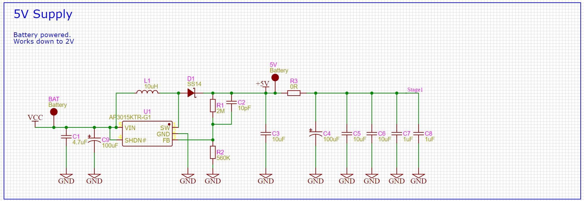
Power:
The two AA batteries will only deliver 2.5 - 3V (Datasheet Energizer). Many IC's require higher voltages., especially high voltage boost converters, which I need for the measurement of >40V Zener diodes.
In this expamle I am using an AR3015KTR boost converter to get to 5V because it was just available. But honestly, every cheap boost converter (min V < 2.4V) will do. Just check what JLC will assemble at the moment you are building it.
![]()
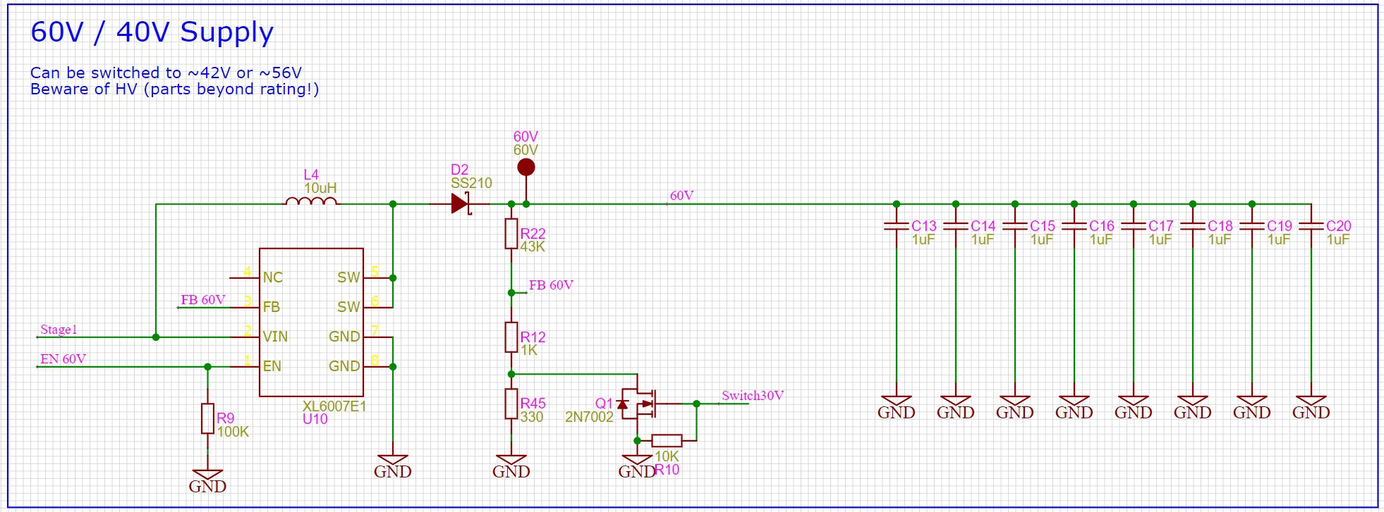
For the high voltage stage, the voltage is made adjustable by placing a MOSFET switch in the feedback path. Messing around with the feedback path, is often not the greatest idea, but in this case, we don't have to be exact with the voltage.
For the voltages we get:
As boost converter, we can again select what is currently offered. Here the XL6007E.
![]()
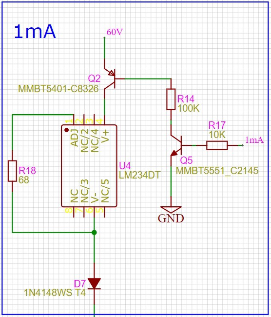
LED supply:
I want to measure the voltage over a Zener-Diode or long LED string. Target is here 1V - 42V, with the option for higher voltages.
The voltage depends on many factors such as temperature and current. To get more useful results, 3 current settings should be available (0.1mA - 1mA - 10mA).
For this, I am using current sources. A PNP transistor in the supply will be used to switch it ON or OFF. Yes, I could have used a MOSFET, but bipolars are a bit more robust, and I don't really need the performance.
But, of course, we need to have enough voltage margin of the supply voltage. Current regulator LM234 is fast and will comensate the voltage difference of up to 40V. This means, with the 60V supply, we should only measure Zener-Diodes with >20V
![]()
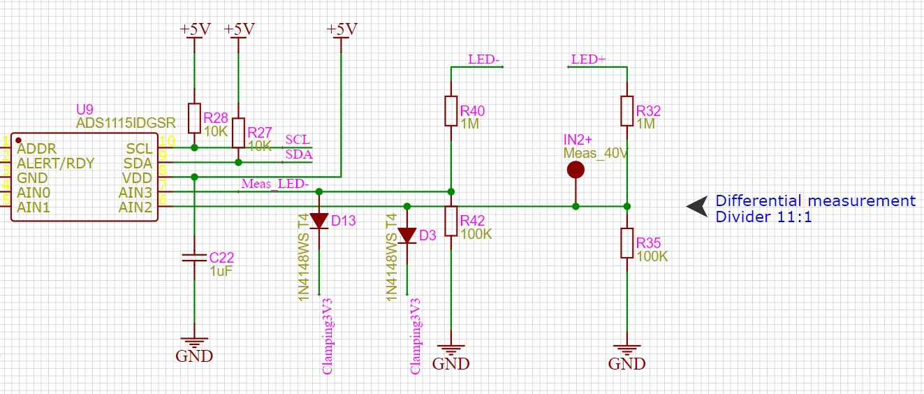
For the actual measurement, I went a bit over board by using the ADS1115. It's not too expensive and has plenty of performance.
Also, as protection of over-voltage, diodes have been added to a 3.3V rail. In this application, you don't want to use a 3.3V Zener directly, because it will leak significant current below 3.3V!!!
![]()
-
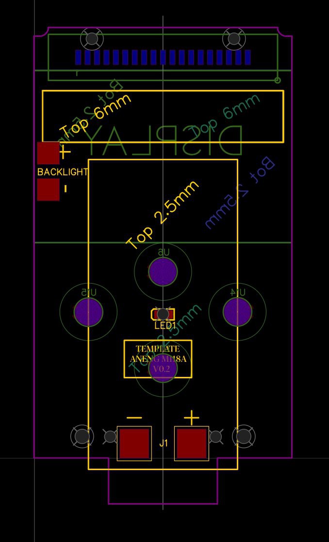
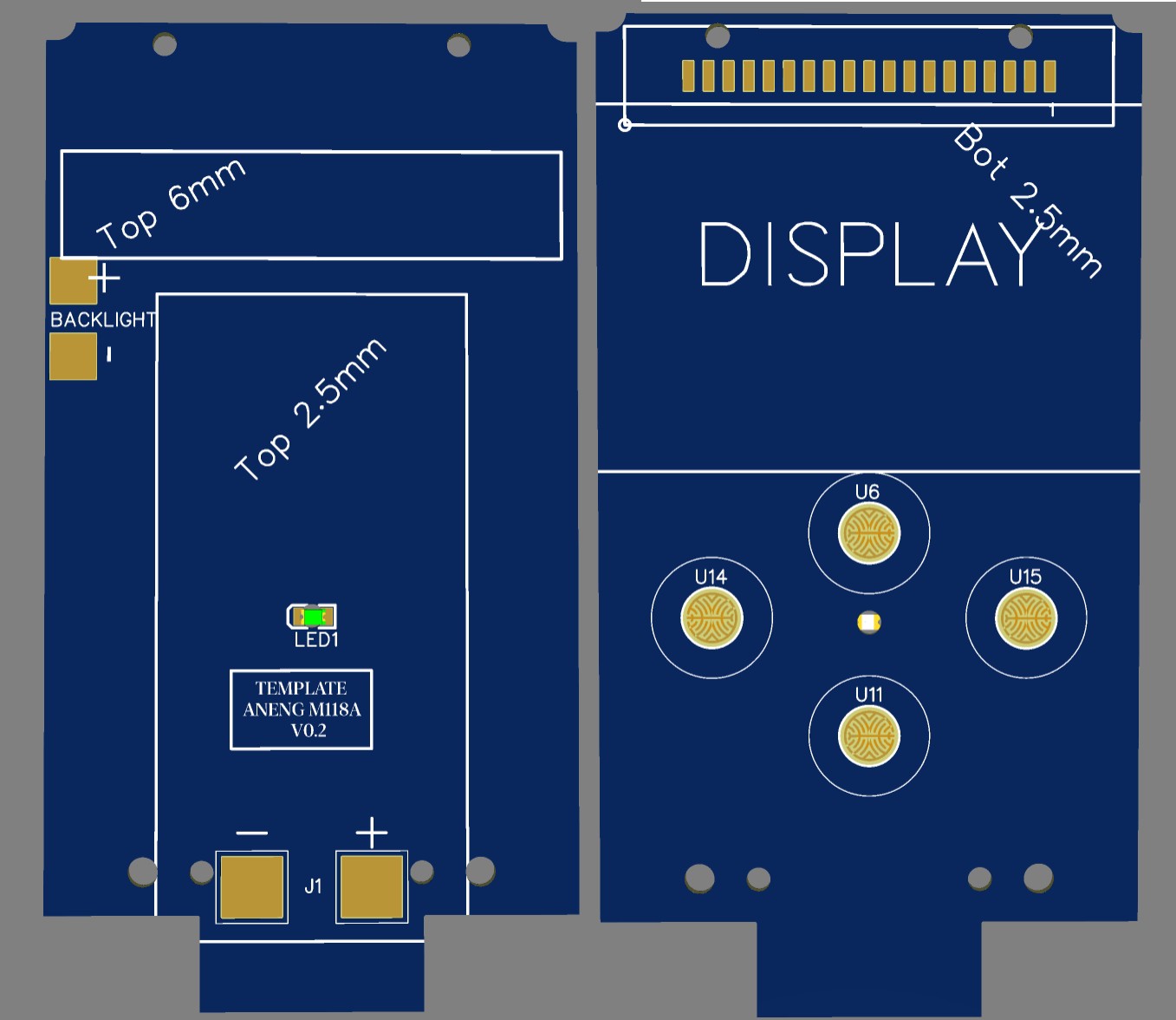
Aneng M118A - PCB template
08/02/2021 at 11:35 • 0 commentsThe dimensions of the original PCB have been copied.
You can find the files here: EasyEDA - Aneng M118A Template
- The LCD pins, button pads as well as battery contacts are placed correctly.
- Notes have been added about the maximum height of components.
The battery compartment and the hinge of the stand take up some space and limit the height. electrolytics and buzzers should be placed left and right of battery compartment.
![]()
![]()
PS: Note the beautiful pattern for the rubber buttons!
-
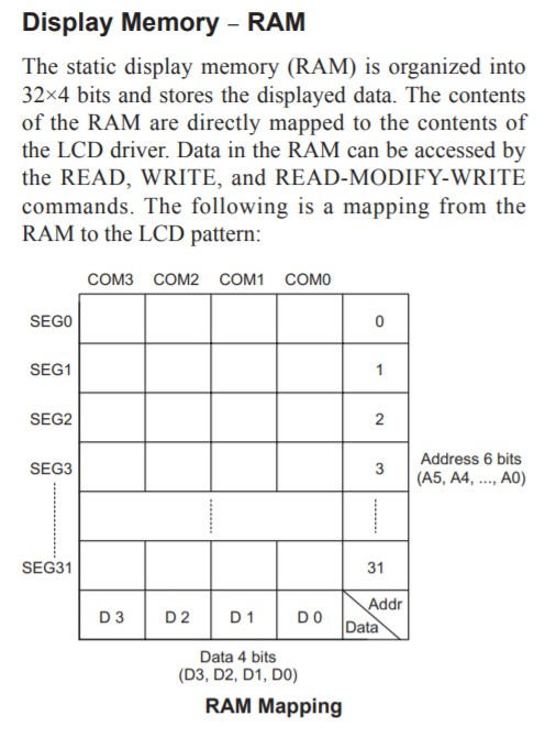
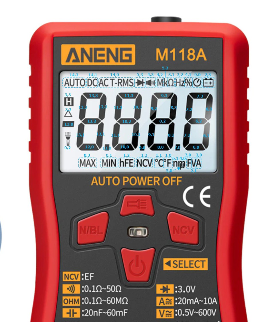
Aneng M118A - LCD mapping
08/02/2021 at 08:06 • 0 commentsThere are two options for figuring out the routing table of LCD segments and pad combinations.
- Observation (Using a scope to analyze the patterns)
- Experimentation (Try out every combination and write down the results)
Since the patterns change very quickly with every chang of the displayed number, I went for experimentation ;)
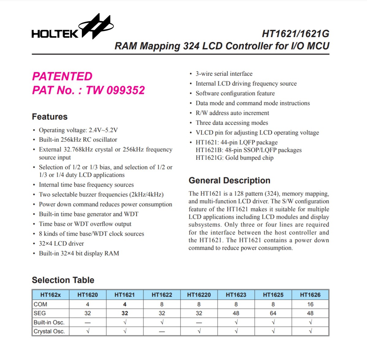
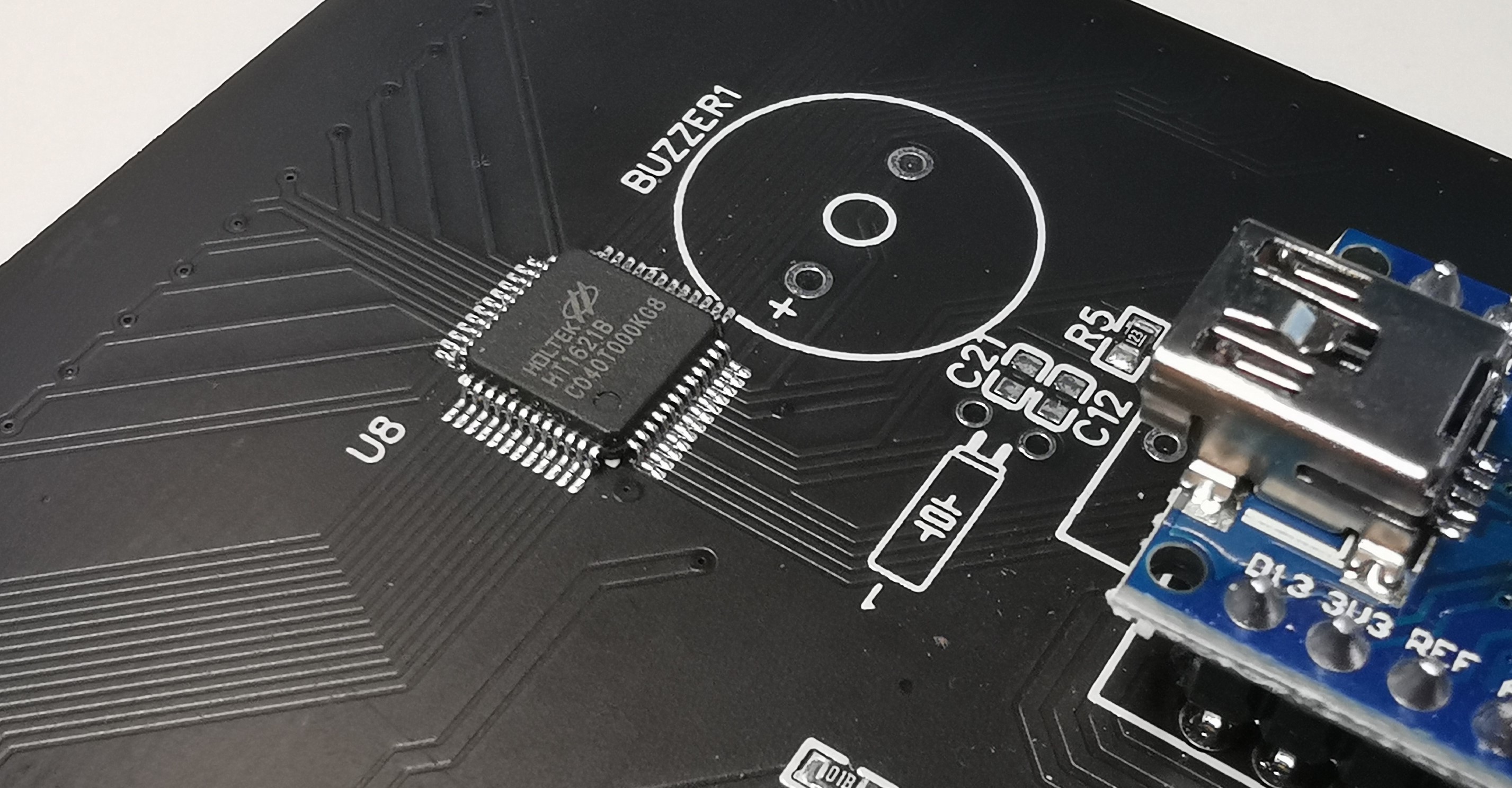
So, I hacked together a breakout board for a display driver. The HOLTEK HT1621B is easily available, cheap and even can be assembled by JLCPCB.
![]()
![]()
An Arduino Nano makes it really easy to interface the HT1621B via I2C.
The HT1621 library provides a simple interface to send data to the RAM of the chip.
void HT1621::write(uint8_t address, uint32_t bits, uint8_t bit_cnt)![]()
I marked out the final mapping. The format is: [SEG, COM]
![]()
-
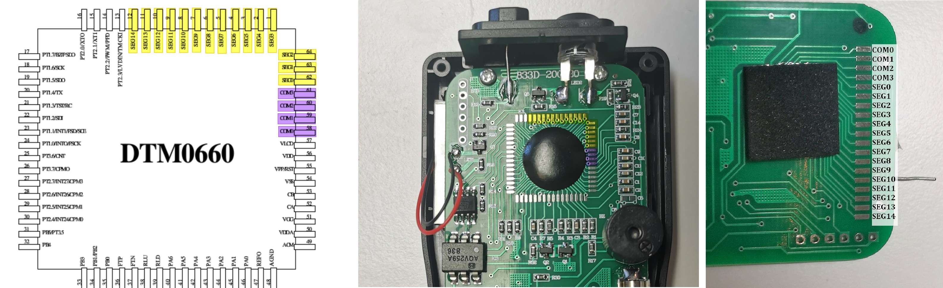
Aneng M118A - LCD pinout
08/01/2021 at 20:47 • 0 commentsHuge challenge is figuring out the LCD pinout.
Having the knowlege that a DTM0660 chip is used, the pinout of the back-connector can be determined.
![]()
That was the easy part. Following is to find out, which combination is connected to which segment...
The LCD screen can be seen as an array. By selecting a COM (common) output and SEG (segment), a specific segment will become black. Of course, driving the segment, should be done with an AC signal so that 0V DC offset is reached. More on that principle can be found in this video of Dave Jones (EEVBlog) https://www.youtube.com/watch?v=mo4_5vG8bbU
-
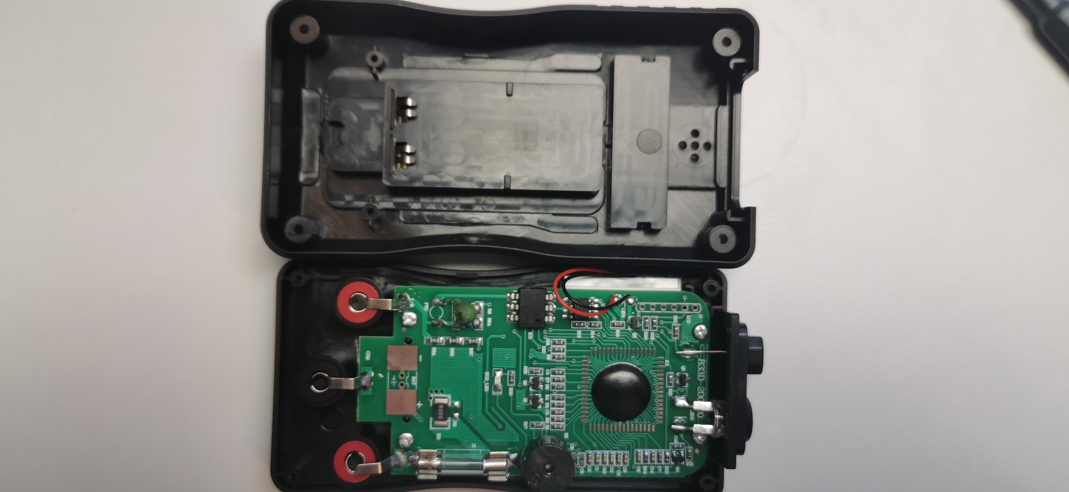
Aneng M118A - Teardown
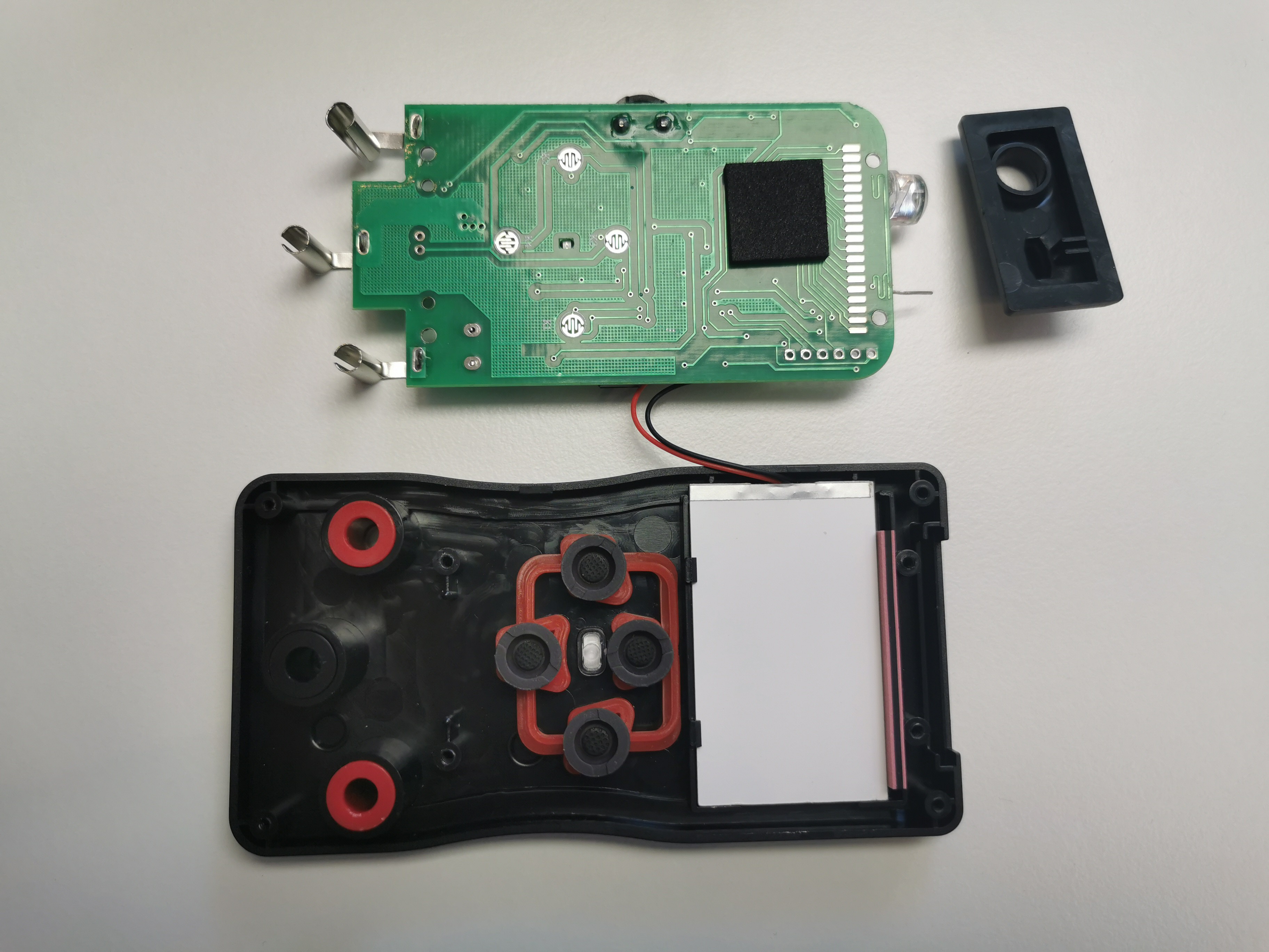
07/31/2021 at 15:05 • 0 commentsThe M118A offers a battery compartment for 2x AA batteries. It is acessible without screws, which is really handy.
Popping it open, we find the very simple PCB with the typical blob IC on the top.
Input protection does not seem adequate - I wouldn't use it as multimeter!
The E-Field probe is just a piece of wire and the LED is a 10mm THT component.
On the front side, we can see the pads for the buttons and the pads for the display glass, which is connected by the zebra strip.
![]()
![]()
-
First DMM - Aneng M118A
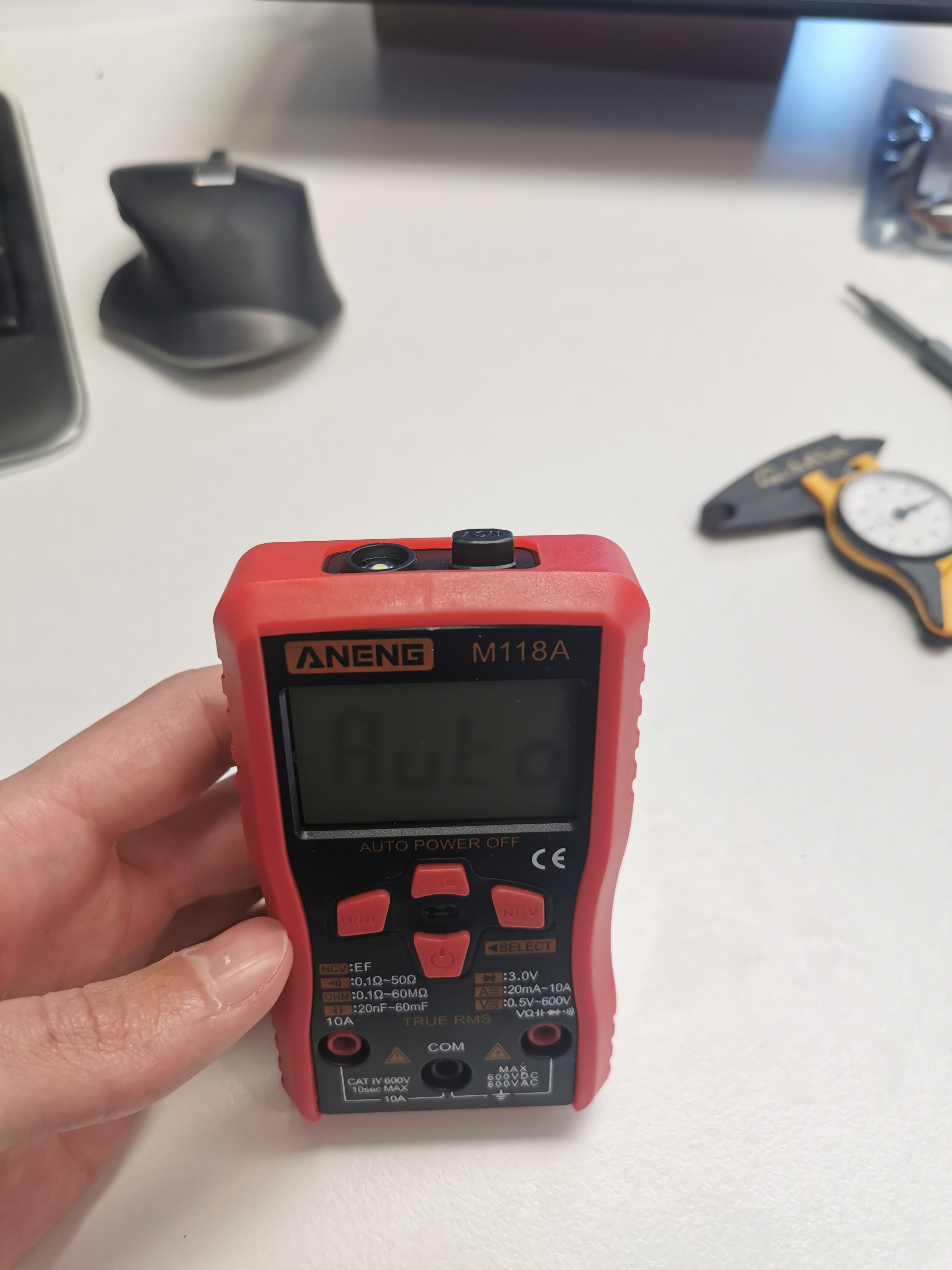
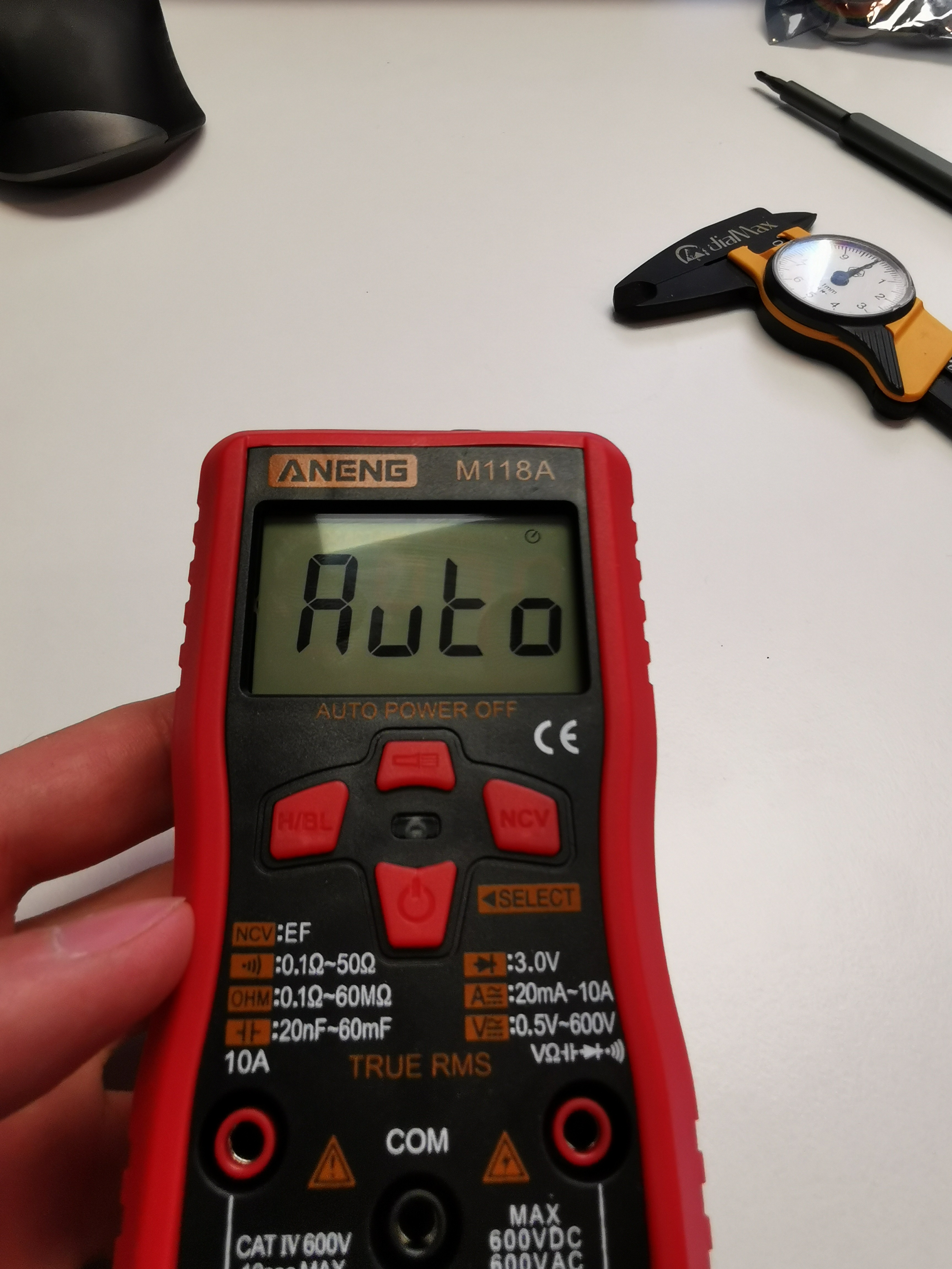
07/31/2021 at 13:42 • 0 commentsAneng M118A has arrived. It costs ~15 $ shipped.
Out of the box, it uses the DTM0660L chipset, since it's the successor of the Aneng AN8001.
You can find an overview of common chipsets here: http://improwis.com/projects/reveng_multimeters/
And information on the DTM0660L here: http://improwis.com/projects/reveng_multimeters/chips/DTM0660.pdf
This DMM was selected because it is ceap, available for everyone and has no traditional selection reel that would cost precious PCB space.
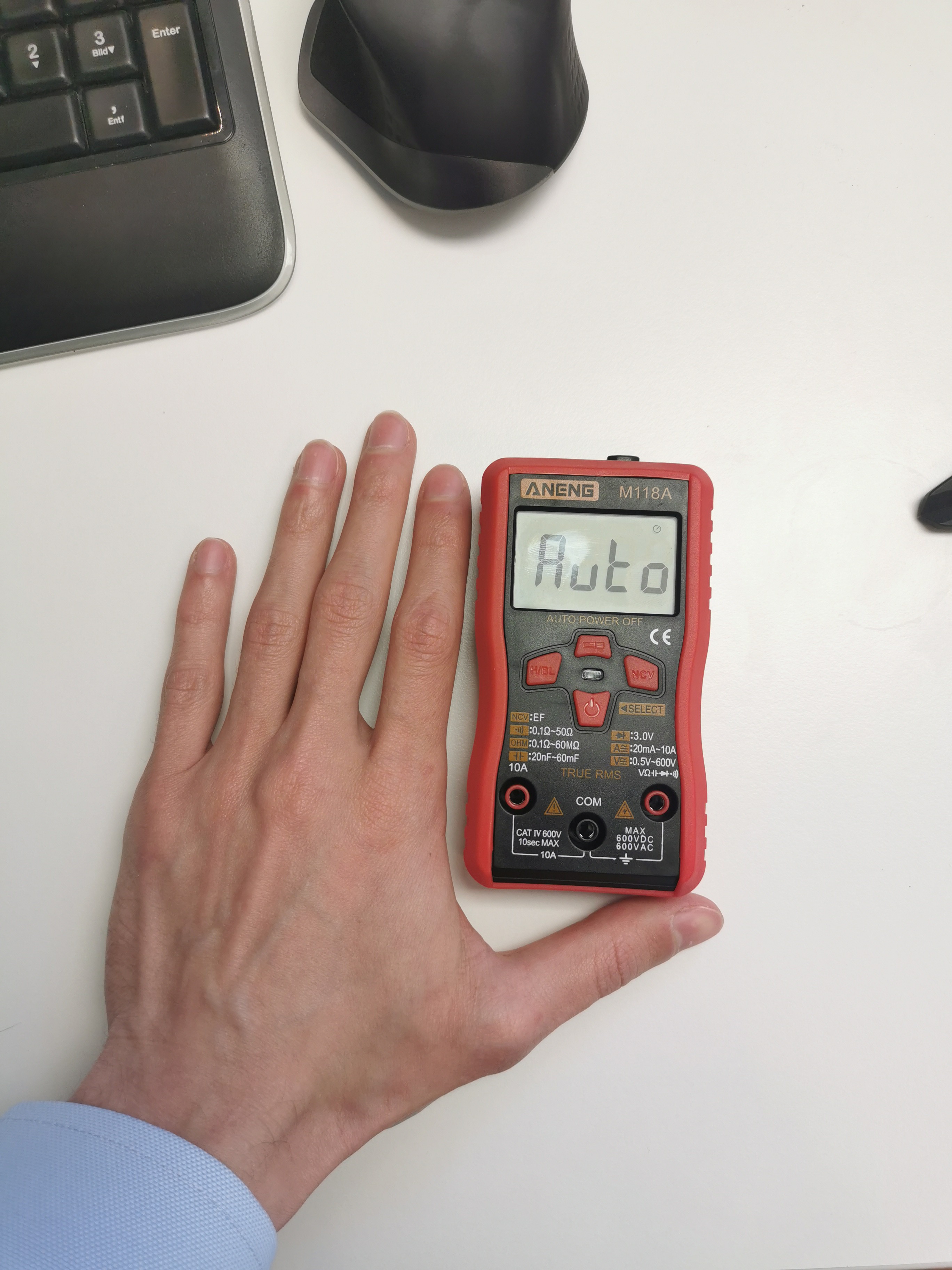
The DMM has a nice rubber housing and the display angles are not too bad.
But a little smaller than expected.
![]()
![]()
![]()
![]()
Hack into an existing Multimeter
Using the impact resistant case of a multimeter for your electronics Demonstrated on the design of a Zener-Tester / LED-Vf-Tester