Brian Brocken
Video can be found here:
Firmware
The machine is currently being controlled by an Arduino mega + ramps board. The firmware currently on the board is marlin. The software being used to control the machine is Repetier host. For the 5-axis part I'll be using grbl as firmware and the software to control the machine will be GrblGru.
Stepper motors
I initially tried to use the standard Nema 17 42mm stepper motor for all the axis to see if this would work, but it quickly became clear they weren't up for the job for the Z and X-axis. The Y-axis was doing fine because it uses 2 of them. So for the Z and X axis i'm now using Nema 23 stepper motors in combination with TB6600 drivers. If you intend to build this, just go straight for the Nema 23 stepper motors as they are more powerful than the Nema 17 ones and are more suited for the job. The motor mounts for both the Nema 17 and Nema 23 motors are included in the files.
Mechanical design
The pieces that hold the frame together are all 3D-printed with the FLsun Super Racer (thanks again to FLsun for sending me this awesome machine) using regular PLA.
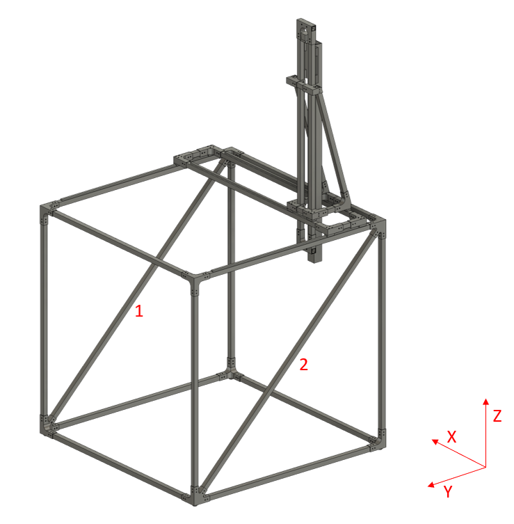
For the frame itself I chose to go with 25x25mm aluminium tubing with a wall thickness of 2mm. This turns out to be working great but if you want absolutely no deflection on the X and Y axis, you might want to increase the wall thickness to maybe 5mm. By increasing the wall thickness you can reduce the deflection without the need to change any of the dimensions of the 3D-printed parts, the outer dimensions of the aluminium tubing stays the same.
Originally I was going to use only 2 diagonal cross beams on 2 sides of the machine like you can see in the picture below.
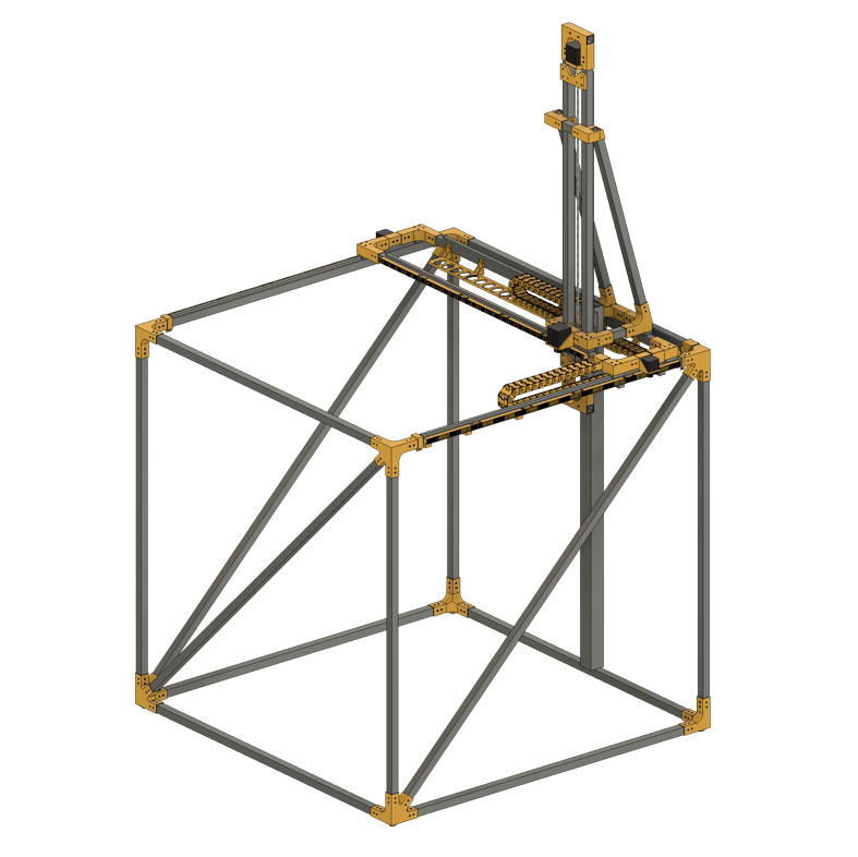
But as you might've guessed, this resulted in the machine being wobbly in the X-axis. So I added another cross beam to improve stability and left the other side open (see picture below) in case large work pieces need to go in or out of the machine. This is still not a perfect solution as there might still be some wobble when the machine is at the open end, so I might add a cross beam that's removable so when larger pieces need to be taken out of the machine, the beam can be taken out.
Because belts might stretch over time on these longer distances I chose to go for rack and pinion gears on this one. These are 3D-printed to keep the cost down but these also decrease the accuracy a bit. But because this machine is intended for larger pieces to be printed with a 1mm nozzle, this shouldn't be a problem. You can swap out the 3D-printed racks and gears for machined ones if you need more precision.
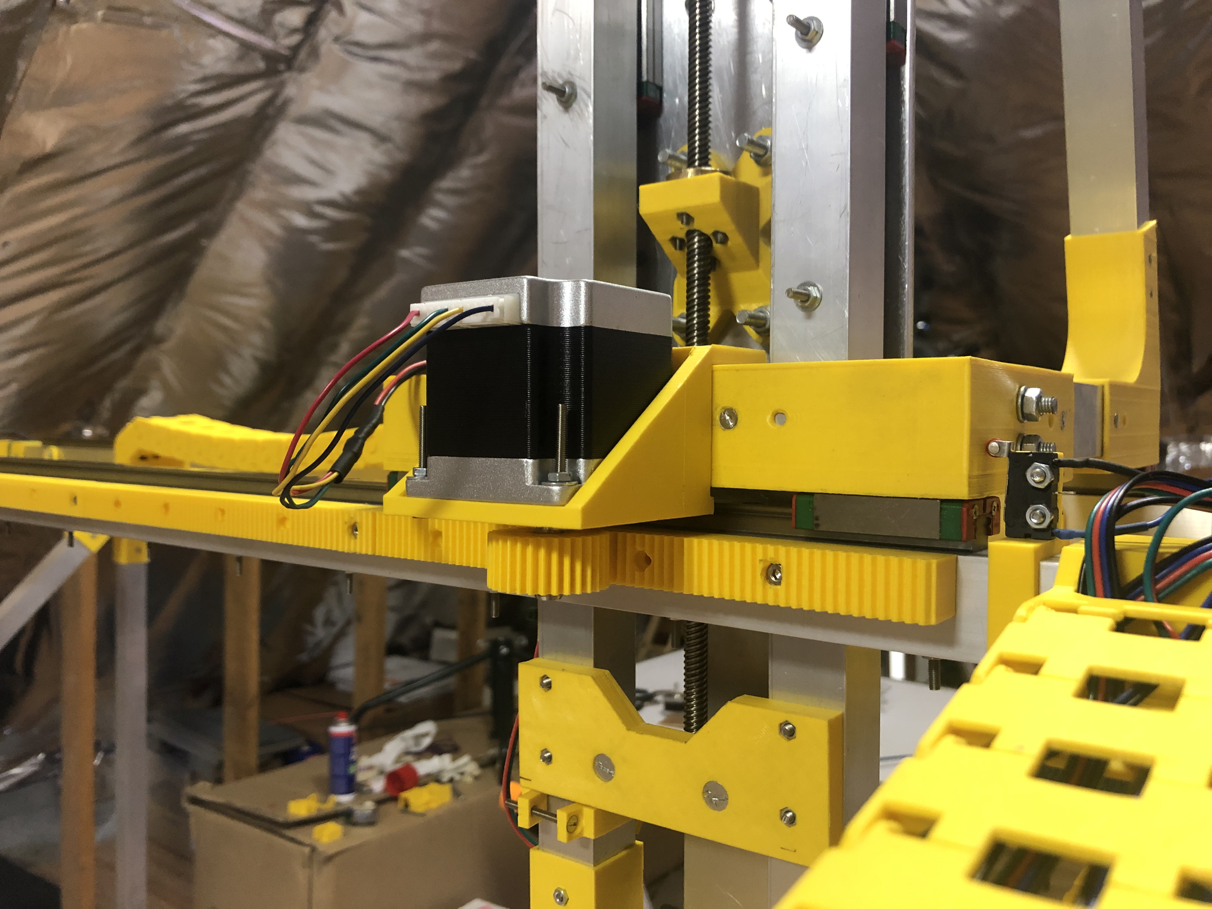
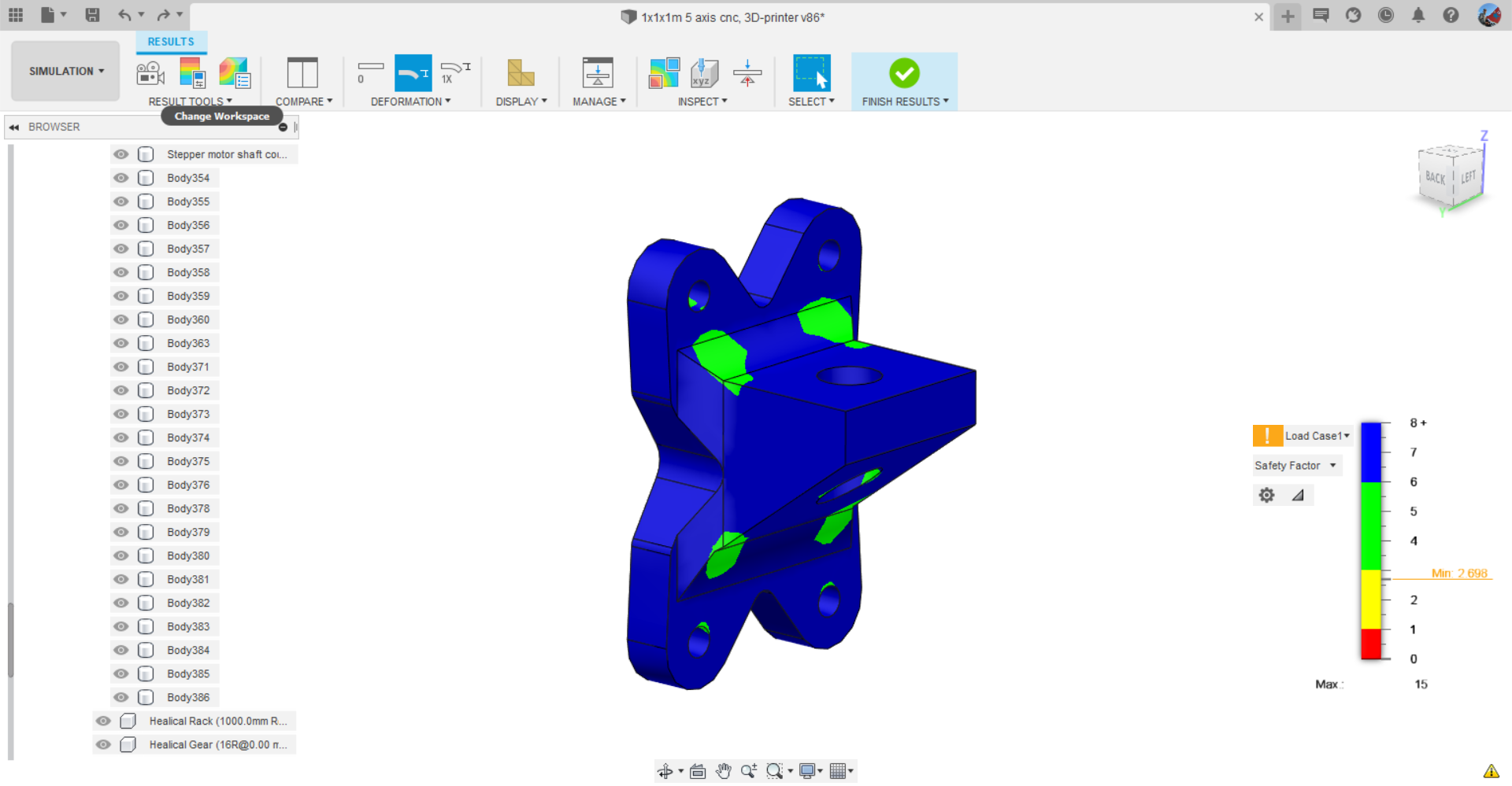
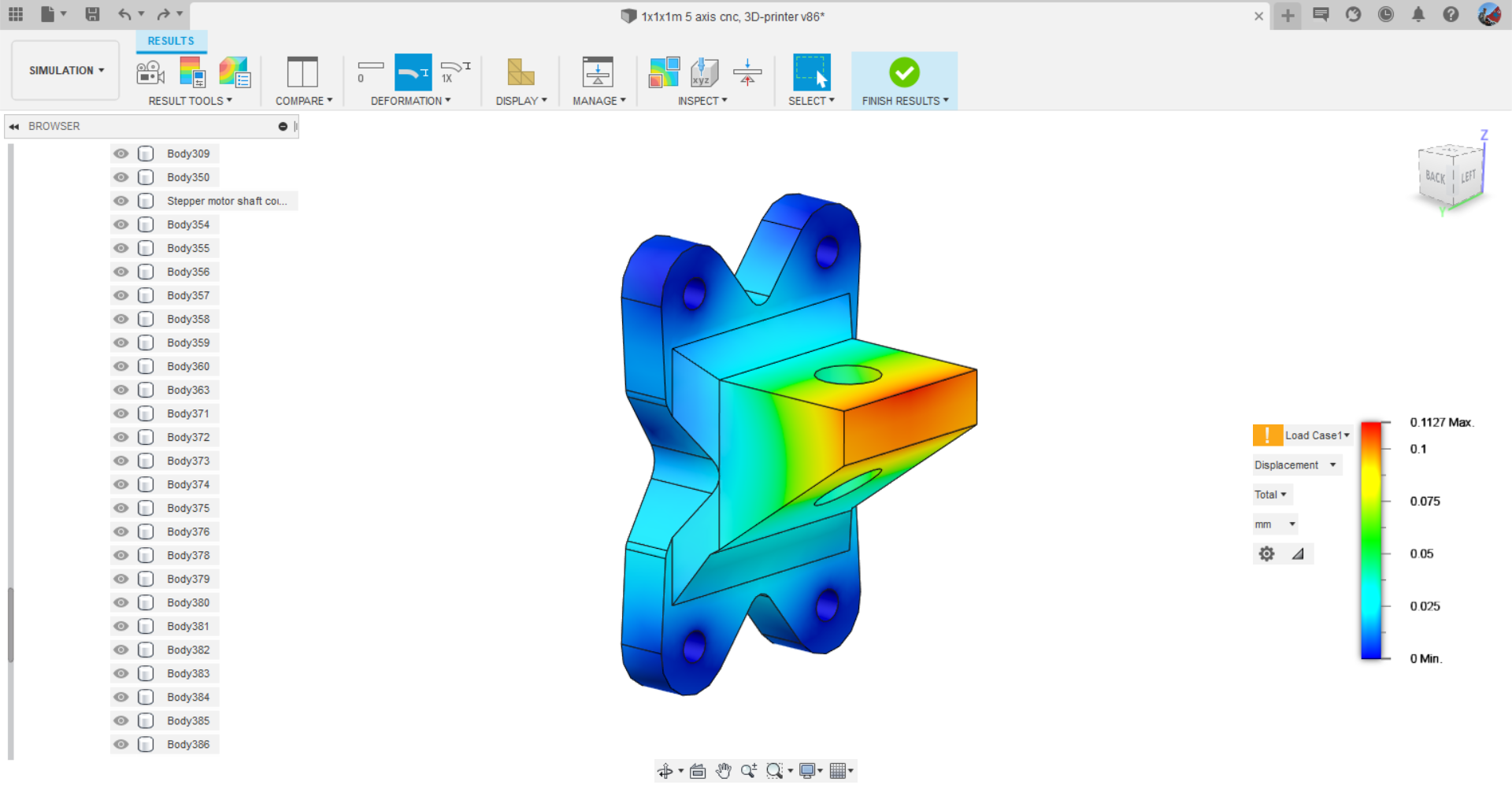
The Z-axis is lead screw driven. The part that holds the nut and connects the lead screw to the Z-axis is 3D-printed. The part is designed to withstand a force of 500 newton (around 50kg) with a safety factor of about 2.7 (theoretical max force of around 135kg), which is more than enough in this use case. The shape has been optimized by the shape optimization function inside Fusion 360 to reduce the amount of material that's needed for the part. and only keep the areas that are under load. The Z-axis itself is an aluminum beam 50x50x1200mm with a thickness of 2mm and is mounted on a 5x120x200mm aluminum plate. The templates for the holes can be find in the file section on this page.
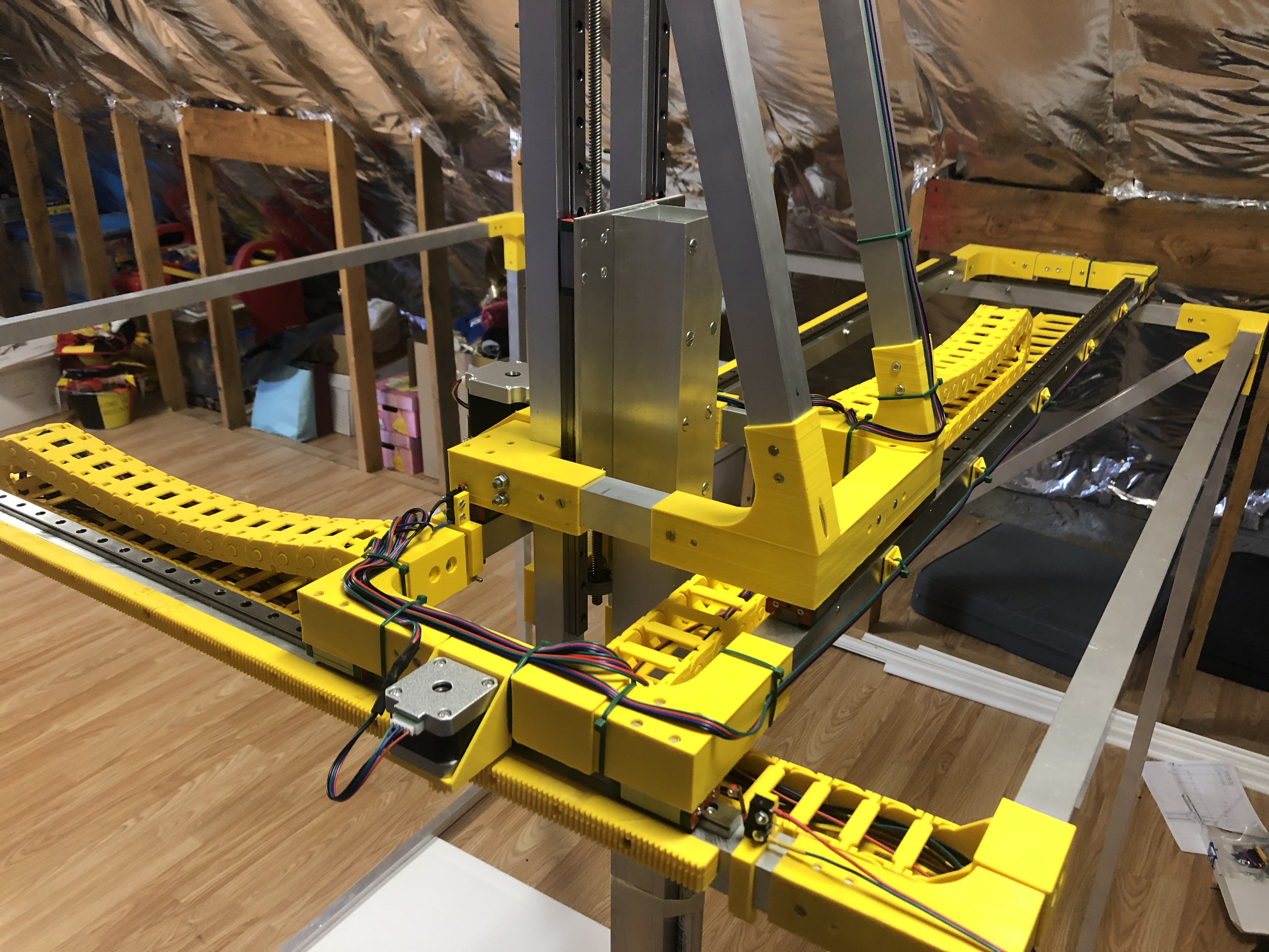
For the linear motion on the X,Y and Z axis I used the MGN12 1000mm linear rails and bearing blocks provided by Banggood (link can be found in the parts list). These are just perfect for this machine and have 0 play in them so they are very precise.
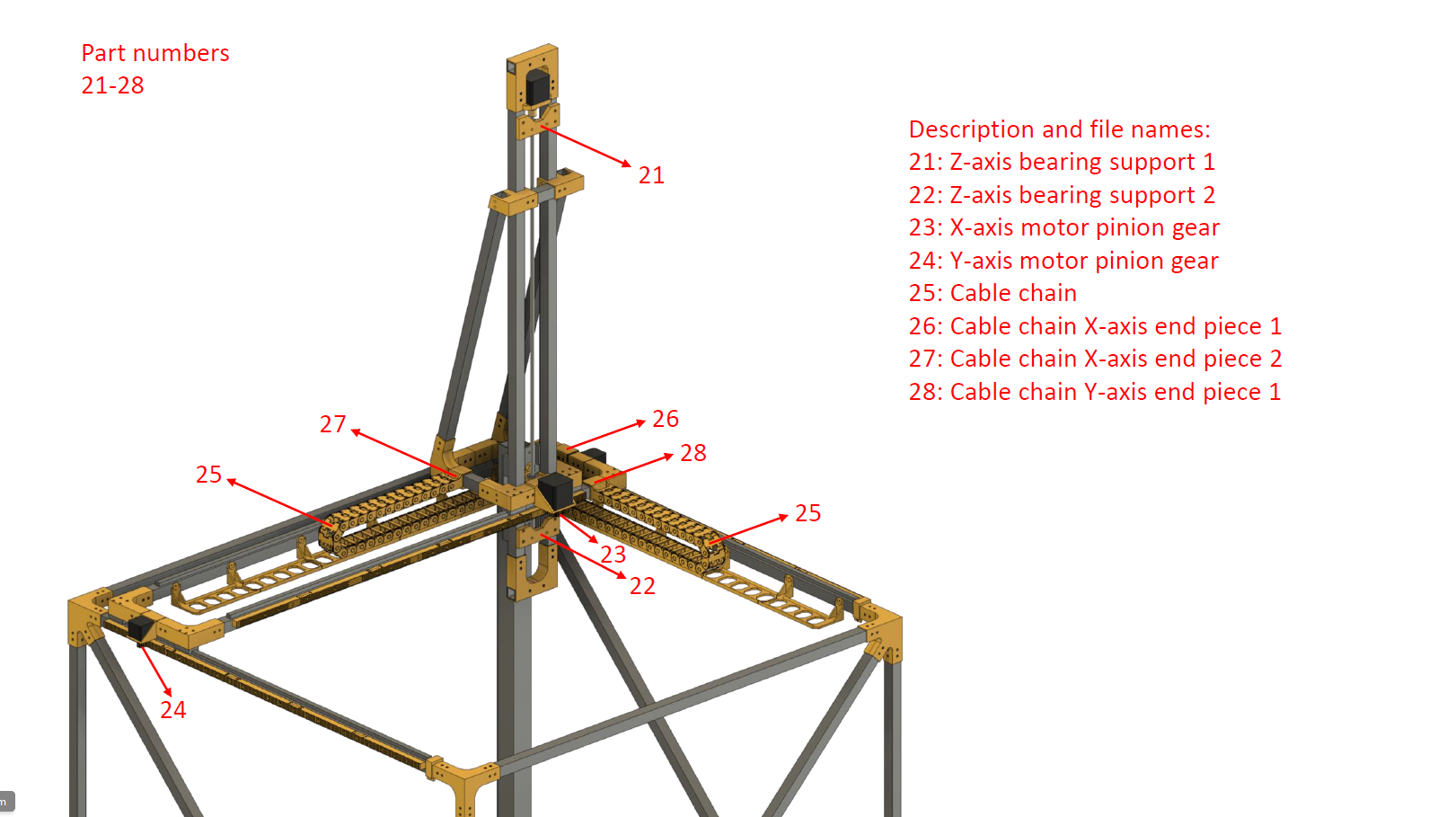
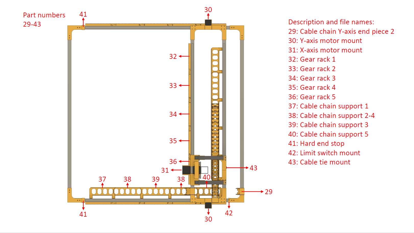
For the cable management I designed and 3D-printed a cable chain in combination with support for it. In places where the cables don't need to move I used 3D-printed cable tie mounts that stick to the frame using double sided tape.
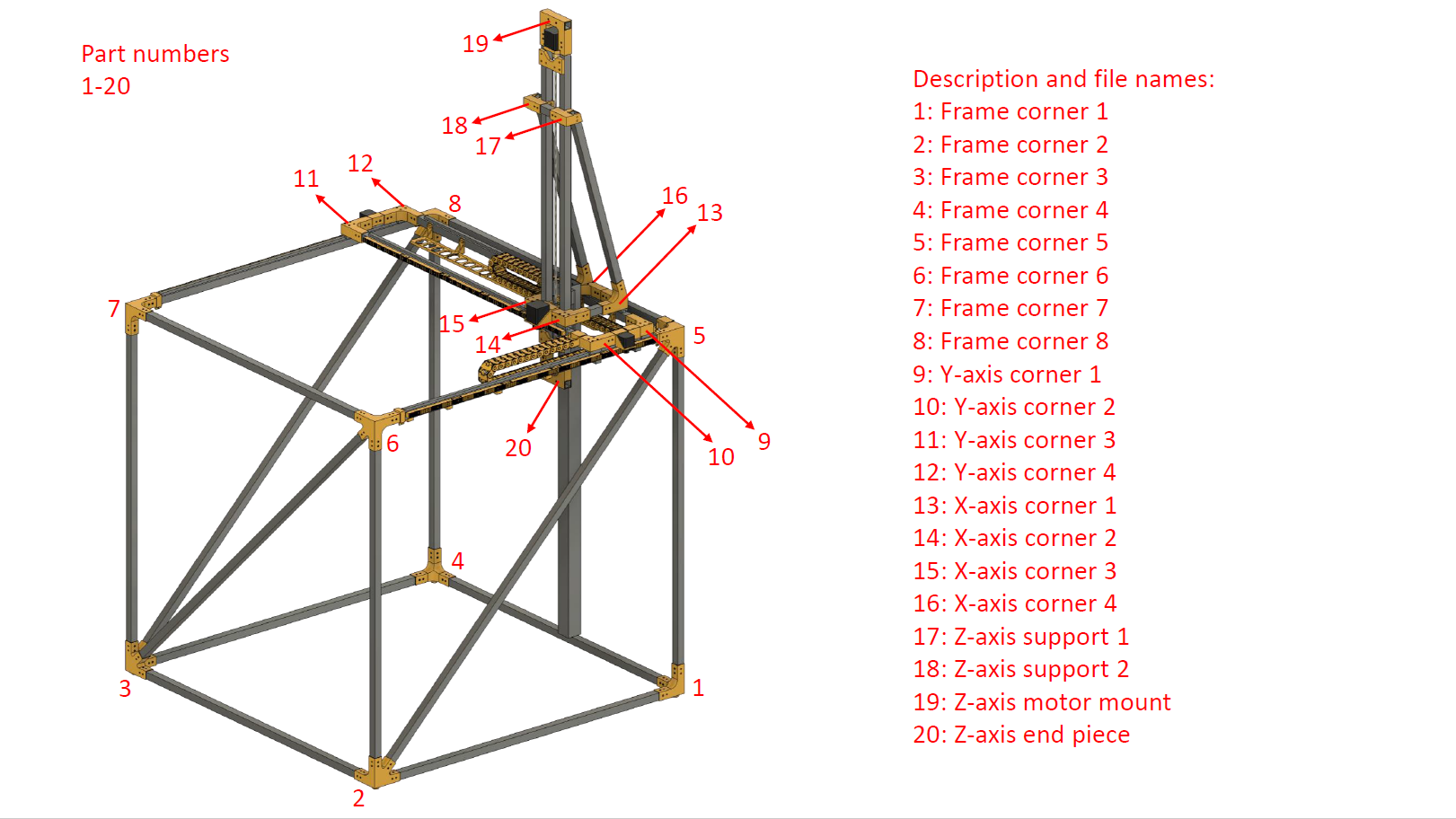
To better understand which 3D-printed part goes where, I made a simple manual showing which component and file name goes where on the machine. A higher resolution pdf has been added to the files section on this page.


 setCREATE
 Rui Caldas
 John Opsahl