 Ken Yap
First I had to correct errors in the modules. Then I needed a NOR gate to combine the reset button with the NOPF reset signal. In addition I have attached a clock generator, a hex instruction address display, input and output pins for the test program, and a LED on output 7.
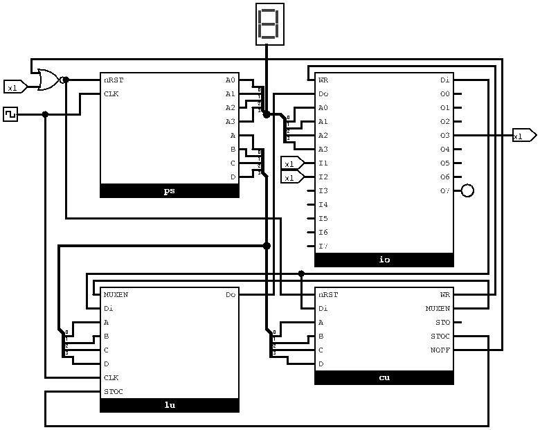
The program simulated was the one used in the Arduino emulator:
LD 1; AND 2; STO 3; STOC 7; NOPF;
and letting the simulation free-run showed it looping through the instructions, and lighting the LED if I1 AND I2 is FALSE; STOC 7 effectively makes the LED show a NAND.
I'll test it a bit more before posting the Logisim files, and decide what the next stage, if any, should be.
Discussions
Become a Hackaday.io Member
Create an account to leave a comment. Already have an account? Log In.