 Robert
Note: I don't have this device with me currently and I din't noted everything, so some things might be incorrect. Also working on a new version of this project (available on GitHub).
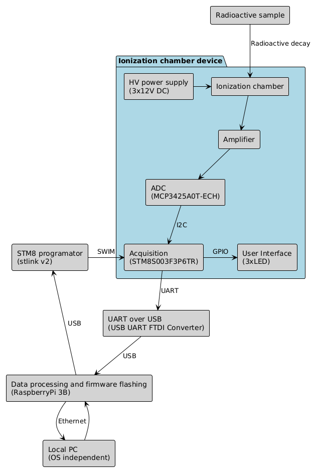
System architecture
Take a look on the diagram below.
The sensor consist of two electrodes place close to each other, but they don't touch. Those electrodes are polarized using 4*12V (the diagram below is incorrect here).
First stage of amplification consist transimpedance amplifier, due to very low signal from photodiodes, feedback resistor of this amplifier have value of 2*50GOhm. Second stage is non-inverting amplifier, third stage is inverting amplifier and then buffer.
The signal is then feed to ADC and checked periodically by microcontroller (note: it's STM8, not STM32, it's a different family). Then the data is further proceeded.
Hardware
Hardware was done using Kicad.
Software
Firmware was compiled using sdcc compiler because gcc doesn't support this family of micro-controllers.
A couple of scripts in Python and R were created in order to gather and analyse the results. Below is and example of the output.

Mechanic
It's important to note that the device won't work without proper shielding from EMI and light, the chassis must be made from metal, and must be grounded.

 fereshteh
 Bradley Worley
 Linus Dillon