 Sagar 001
This is the 1st part of our LCR tutorial in which we are going to make an inductance meter. In the upcoming parts of this series, we will upload information and circuit diagrams of the capacitor and resistance meter.
Inductance meter:
An inductance meter is used to measure the unknown inductor value. For more precision and accurate readings, we will use a microcontroller (Arduino) as the brain of the circuit.
Inductor meter idea:
We usually need an inductor to make tank circuits while working with radio frequency, power circuits, and amplifiers. But we cannot measure the value of the inductor in our simple multimeter. So, either we can buy one or DIY (make). LCR meters are too expensive, that’s why we are making this inductor meter.
Components required:
1) Arduino Uno
2) LM339 OP-AMP
3) 1N4007 diode
4) 150 ohm, 330ohm resistor
5) 16X2 LCD with I2C to reduce connections
6) 5V battery
7) 2x 100nF capacitors (non-polar)
8) Some jumper wires (if working with breadboard)
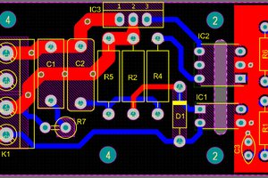
Circuit diagram:

Breadboard circuit:

Gerber files:

Gerber file link is given below to order Gerber files, Upload files to NextPcb and get your first PCB absolutely free of cost.


NextPCB is one of the most experienced PCB manufacturers in the world, focusing on PCB and PCBA for over 15 years, certified by IATF16949, ISO 9001, ISO 14001, UL, RoHS, CQC and REACH. recently, NextPCB has acquired KiKiPCB, to celebrate this good news, NextPcboffers Up to 30% off for PCB orders, and Up to 20% off for PCBA orders, besides, every new customer could enjoy $0 prototyping PCB!
Click to order now: https://www.nextpcb.com/midsummer-sale-on-nextpcb.html?code=sagarjm
By the way, NextPCB designed and developed a PCB design checker(for free now) to check the manufacturability of your file, click to have a try: https://www.nextpcb.com/nextdfm.html?code=sagarjm
Circuit details and working:
Circuit also has an OP-AMP; we are using LM339 due to its simplicity. Here, the Operation amplifier is used as a comparator, which measures the voltage at two instants and compares them. We will discuss the operational amplifier as a comparator at the end of this tutorial.
330ohm resistor is used as a pull-up resistor and connected to PIN 1 of the Lm339 to Arduino digital pin 11. 150ohm resistor is used after diode and further connected to digital pin 13 of the Arduino.
We are using here 104number (2pcs) capacitor 0.2uf (one of 100Nf). The value 2.E-7 can be changed if you are using a different value capacitor. In which value 2 represents the capacitance value (0.2uf).
We can change the op-amp to lm358, 741, or any other having the same configuration. But low noise operational amplifier is preferred more in this case.
Download files and diagrams: ![]()

DOWNLOAD GERBER FILES DIAGRAMS AND CODE FROM HERE
Code details:
1) Initializing all the values:
2) Selecting the capacitor value:
3) Conversion of values milli-henry and micro-henry (mH and uH):
4) Printing the result through serial monitor:
5) Printing the result through 16X2 LCD:
Arduino code:
//[code]
//Circuit and code is uploaded by Circuitkicker.com
//some important things:
// 1) If using Serial monitor to read the value of inductor then select 115200 boud.
// 2) Adjust the value by using fixed inductor by changing 2.E-7 line.
// 3) We will get acuurate readings because of many iteratations.
#include <Wire.h>
#include <LiquidCrystal_I2C.h>
LiquidCrystal_I2C lcd(0x27,20,4); //sometimes the adress is not 0x3f. Change to 0x27 if it doesn't work.
//13 is the input to the circuit (connects to 150ohm resistor), 11 is the comparator/op-amp output.
double pulse, frequency, capacitance, inductance, inductance_mH;
void setup(){
lcd.init();
... Read more »
 hesam.moshiri
thankyou