 Petteri Aimonen
In the comments of the Hackaday post about this project, a question was asked why I chose to use ferrites instead of a linear regulator for filtering the output of the SMPS.
The short answer is: Because linear regulators do not do much filtering above 10 MHz. But I realized that I've never actually verified that assumption, so I decided to do some tests.
On what frequency is the noise?
First of all, what does the noise at the output of the 1.4 MHz SMPS look like? Is the ripple mostly at the 1.4 MHz fundamental frequency, or is it higher?
The SMPS output capacitor is 10 µF nominal, which is actually about 5 µF due to effects of DC bias. The load current is 90 mA. Calculating from this, we can expect a fundamental frequency ripple of about 13 mV before any filtering. Scope measurements confirm this.
But there is up to ±200 mV switching spikes that have much higher frequencies:
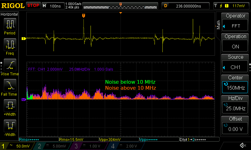
By doing a FFT analysis and setting both frequency and vertical axis to linear mode, we can estimate the amount of total noise in frequency bands by looking at the area under the curve. As seen above, the noise is quite wideband and evenly distributed up to 150 MHz (at which point the scope bandwidth starts to limit sensitivity). Because the area above 10 MHz is much wider than the area below 10 MHz, the high frequency noise contributes most of the total noise amplitude. Furthermore, the operational amplifier is more sensitive to power supply noise at higher frequencies - OPA659 itself has a PSRR of 55 dB at 1.4 MHz, but only 15 dB at 100 MHz.
How well do LDOs block high frequency noise?
Most common linear regulators are only rated up to 1 MHz, but there are high-PSRR models that have ratings up to 10 MHz. For this test, I am using TPS7A2030 regulator, which has specified PSRR of 50 dB up to 10 MHz. How well does it block noise above this frequency?
I made a quick test circuit, where NanoVNA feeds a high frequency signal through C2 to the input, while DC current flows through L1. A small problem in the measurement is that I couldn't add any kind of input filter capacitor, as NanoVNA wouldn't be strong enough to drive a strong ripple into it. L1 isolates the input capacitor for high frequencies, so that NanoVNA is able to make about 20 mV ripple at the input of the regulator. I calibrated NanoVNA v2 against the VIN point, i.e. any losses in R1 and C2 should be cancelled.
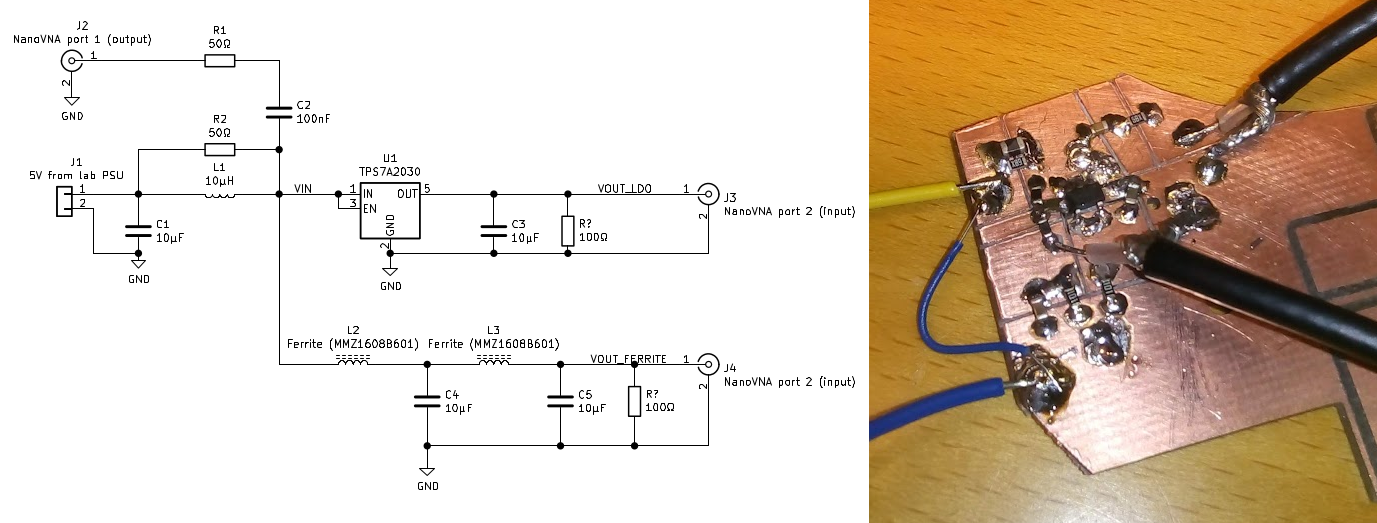
(Note: I'm using the NanoVNA v2 that has DC blocking capacitors integrated. If your VNA does not, check the maximum voltage rating and add a series capacitor if needed.)
Here are the results. Blue curve is VOUT_LDO and yellow curve is VOUT_FERRITE:
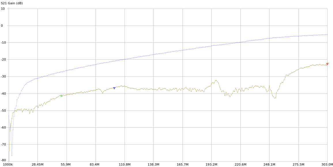
As expected, LDO does a very good job of filtering out low frequency noise. Because of the loading and noise level of the VNA, the measurements at 1 to 5 MHz fluctuate a bit, but the blue LDO curve is generally lower there. For some reason I'm not quite achieving the specified 50 dB PSRR for the regulator at 10 MHz, so there may be some defiencies in my measurement setup.
But in general, this seems to support my assumption that a ferrite + capacitor filter will do a better job of filtering at the high frequencies that are of importance here.
But that was the easy part
In reality, filtering out the noise that gets conducted directly through the output power rails is the easy part. The difficult part is inductive and capacitive coupling, which gets quite strong when the distance between the SMPS and the amplifiers is only 15 mm.
Basic methods to reduce this is to use shielded inductors and to keep the SMPS layout as compact as possible. The largest current spikes are on the input side of the SMPS, so that needs filtering also. Adding shielding around the SMPS section can help also, but it complicates manufacturing so I would like to avoid it if possible. A synchronous rectification SMPS chip would typically reduce noise also, but I haven't found a suitable one for dual-sided ±6V power rails.
Finally, it is not necessary to fully eliminate all power supply noise. Its effect just has to be significantly smaller than the inherent thermal noise of the amplifiers.
Discussions
Become a Hackaday.io Member
Create an account to leave a comment. Already have an account? Log In.
I think you'd get better results using a different linear regulator.
There was a question on the "Electrical Engineering StackExchange" about this. (https://electronics.stackexchange.com/questions/477664/are-all-linear-regulators-bad-at-filtering-input-ripple-or-really-as-bad-as-da)
How well a linear regulator can "clean up" high frequencies depends on the internal circuitry of the regulator. Low drop out and low quiescent current regulators perform worse in that respect.
Regardless, your tests clearly show that your method was better for your project. Cold, hard, numbers beat theory and opinion any day.
----------
Nifty idea to use the Nano-VNA that way. I've got one, and now have another idea for things to do with it.
Are you sure? yes | no
That is correct. But the TPS7A2030 is the very best LDO in this regard that I know!
Are you sure? yes | no