 Mitsuru Yamada
1. System requirements
The CPU of the computer to be run is the 6502, which was widely used about 45 years ago. The total memory requirement for the system and user area is 16kB. The user interface uses a RS232C serial terminal. Figure 1 shows the execution of this interpreter CI-2 (Computation Interpreter -2).
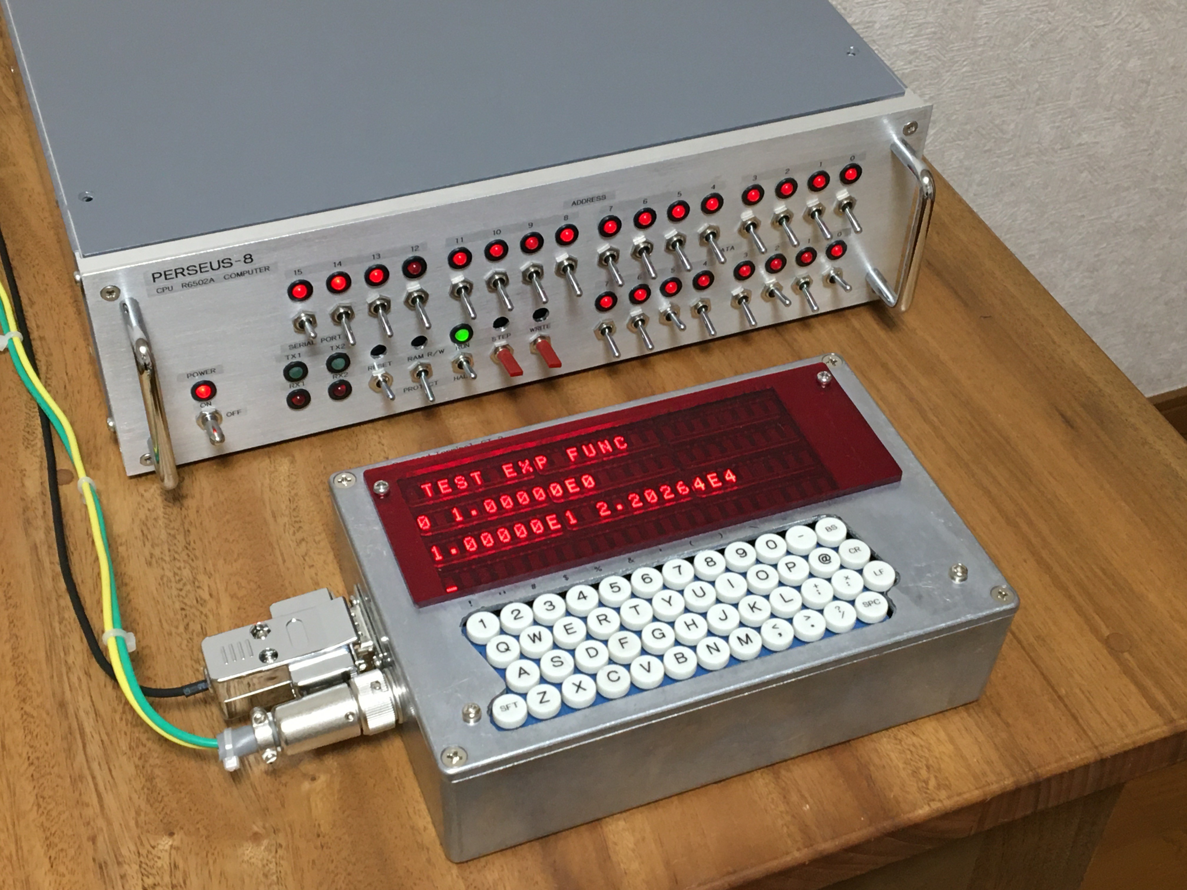
Fig.1 Floating point interpreter CI-2 running on my 6502 computer PERSEUS-8
2. Language specification
The language specifications are listed in the following. This specification was not defined exactly at the beginning, but was the result of trial and error. The details of the language specification are shown in the attached file (Specification of Floating Point Computation Interpreter CI-2 V2_0.pdf).
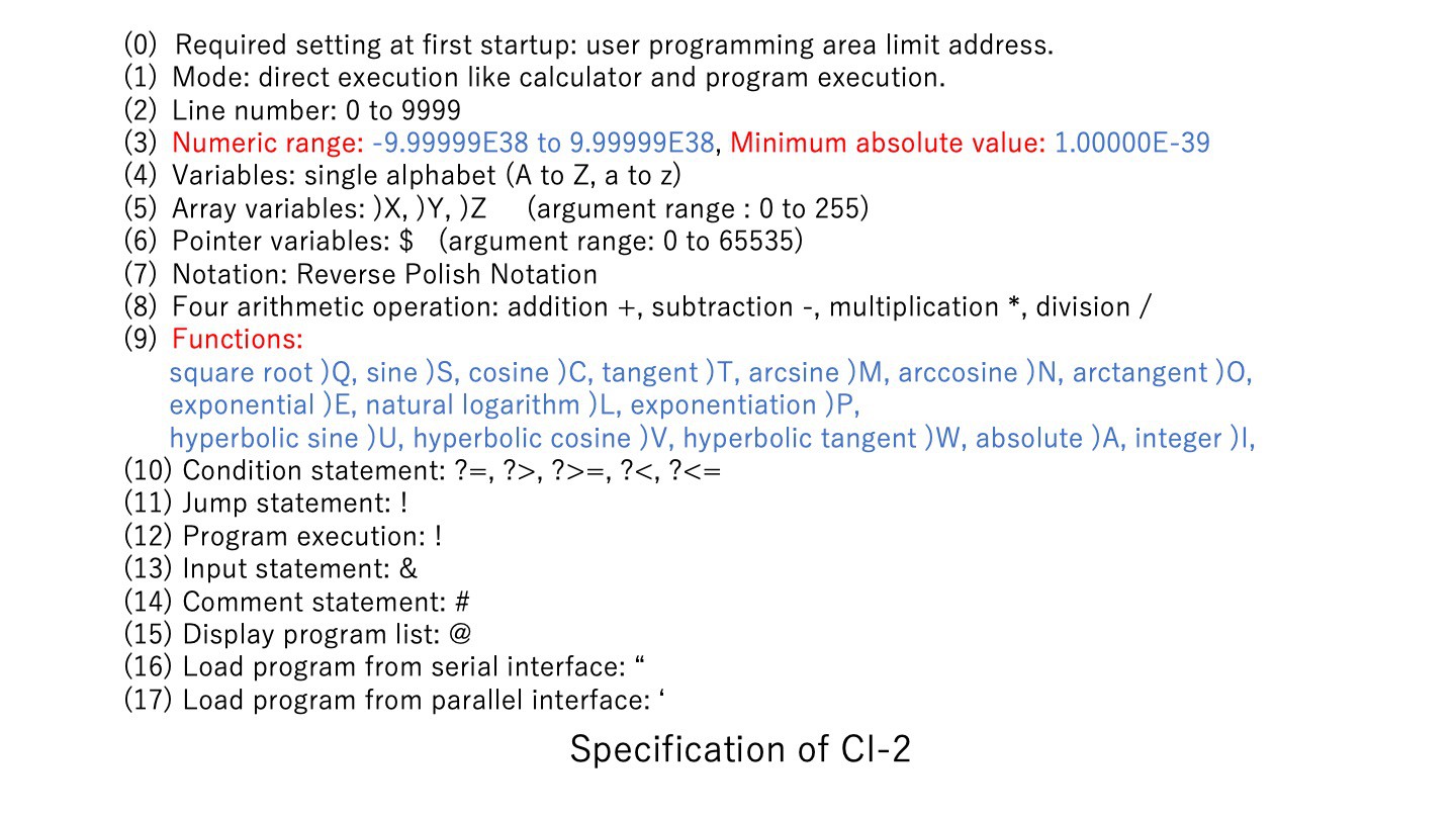
The numeric values were set to 32-bit single-precision floating-point type. In order to simplify the conversion of ASCII code to numbers, BCD notation was used instead of binary. Therefore, the number of significant digits and the numerical range are inferior to those of general single-precision arithmetic systems. In order to avoid parsing, variables and instructions were defined as single letters of the alphabet. The formula uses RPN (Reverse Polish Notation). This is also to avoid parsing.
There are three one-dimensional array variables:)X,)Y,)Z. The arguments range from 0 to 255. This alone occupies 3kB of memory. There is no statement equivalent to a FOR loop, but I decided to use a conditional branch and a jump to the specified line number instead. Therefore, it is not suitable for large-scale programming.
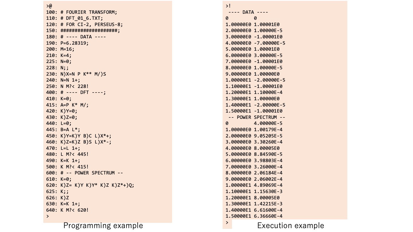
The following is an example of programming description and its execution. The line number 230 ‘N)X=N P K** M/)S’ is ‘X(N)=sin((K*P*N)/M)’ in a typical language description. The line number 480 ‘L M?< 445!’ means ‘if L<M then go to 445’. Command ‘@’ from the terminal is the display of the program list, and command ‘!’ is to execute the program.
The upper limit of the user program area is set by manually writing to the zero-page area only at the first startup so that it can be varied according to the memory capacity of the system. In PERSEU-8, the memory limit is $1FFF, so type 130$=31 in the direct mode pointer variable. This will set the upper byte $1F of the upper memory limit address in the register $0082. In PERSEUS-8, the user memory area is 4 kB, so the maximum number of characters in a user program is approximately 3840
3. Software configuration
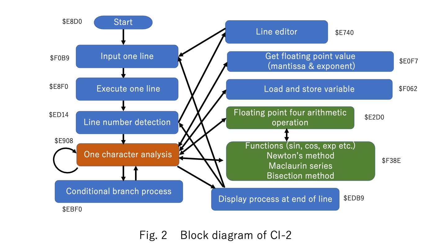
Figure 2 shows the block diagram of this interpreter system. The system will wait for one line of input after startup. After inputting a single line from the serial interface, it analyzes it one character at a time from the left of the line buffer. Here, if a line number is detected at the beginning of a line, the process moves to the line editor. If no line number is detected, parse one character at a time as direct execution mode. This ‘MAIN LOOP’ process is mapped from address $E8F0 in the assembly code. If it is a number, it is converted to BCD and stored in the floating point register. This ‘GET FLOATING POINT’ process is mapped from address $E0F7 in the assembly code. If it is an arithmetic operator or a command, it moves to the respective processing routine. If a ‘CR’ code is detected, perform the assignment and register value display, and return to waiting for one-line input. This ‘END LINE’ process is mapped from address $EDB9 in the assembly code.
Program execution is performed by setting the execution flag upon detection of a ‘! ‘ code and the execution flag is set. Once the execution flag is raised, a single line of analysis is executed from the beginning of the program area. In the case of a conditional branch statement, the line with the line number that matches the line number of the jump destination is searched from the top of the program and executed from there. This ‘CONDITION’ process is mapped from address $EBF0 in the assembly code.
4. Floating point expression
The floating point expression in this system is shown in Fig. 3. A floating-point variable consists of a 3-byte 24-bit mantissa part, a 7-bit exponent part, and a 1-bit mantissa sign. I use BCD for notation because it is easy to convert ASCII codes to numbers, and because the register values can be intuitively read on the binary LED display of the front panel of PERSEUS-8 as shown in value examples of Fig.3. In this 6502 CPU, setting a flag, so the implementation program is simple can perform the BCD operation.
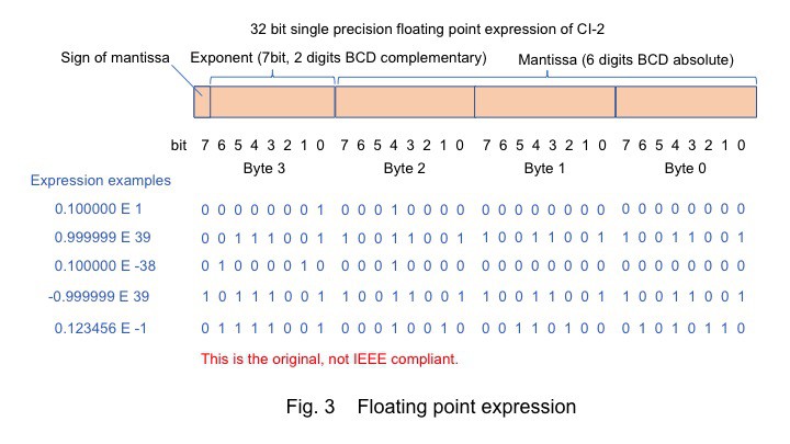
The exponent part is expressed as a complement instead of a general offset, because I thought it would be easier to understand the values when debugging intuitively. However, the process of adding and subtracting, I felt that it is troublesome to compare the exponents of two variables making them equal by using complement. Furthermore, in the 6502 CPU, a complement is the complement of 100 in the case of BCD, but in this case, it is 7 bits, so it had to convert it to the complement of 80.
5. Four arithmetic operation
Figure 4 shows the memory map and register structure of this system. The machine language instructions of this 6502 CPU basically allow only 8-bit addition and subtraction for arithmetic operations. Therefore, the registers for floating-point arithmetic must be defined in memory, and the processing of the mantissa and exponent parts of the four arithmetic operations must all be implemented by an algorithm.
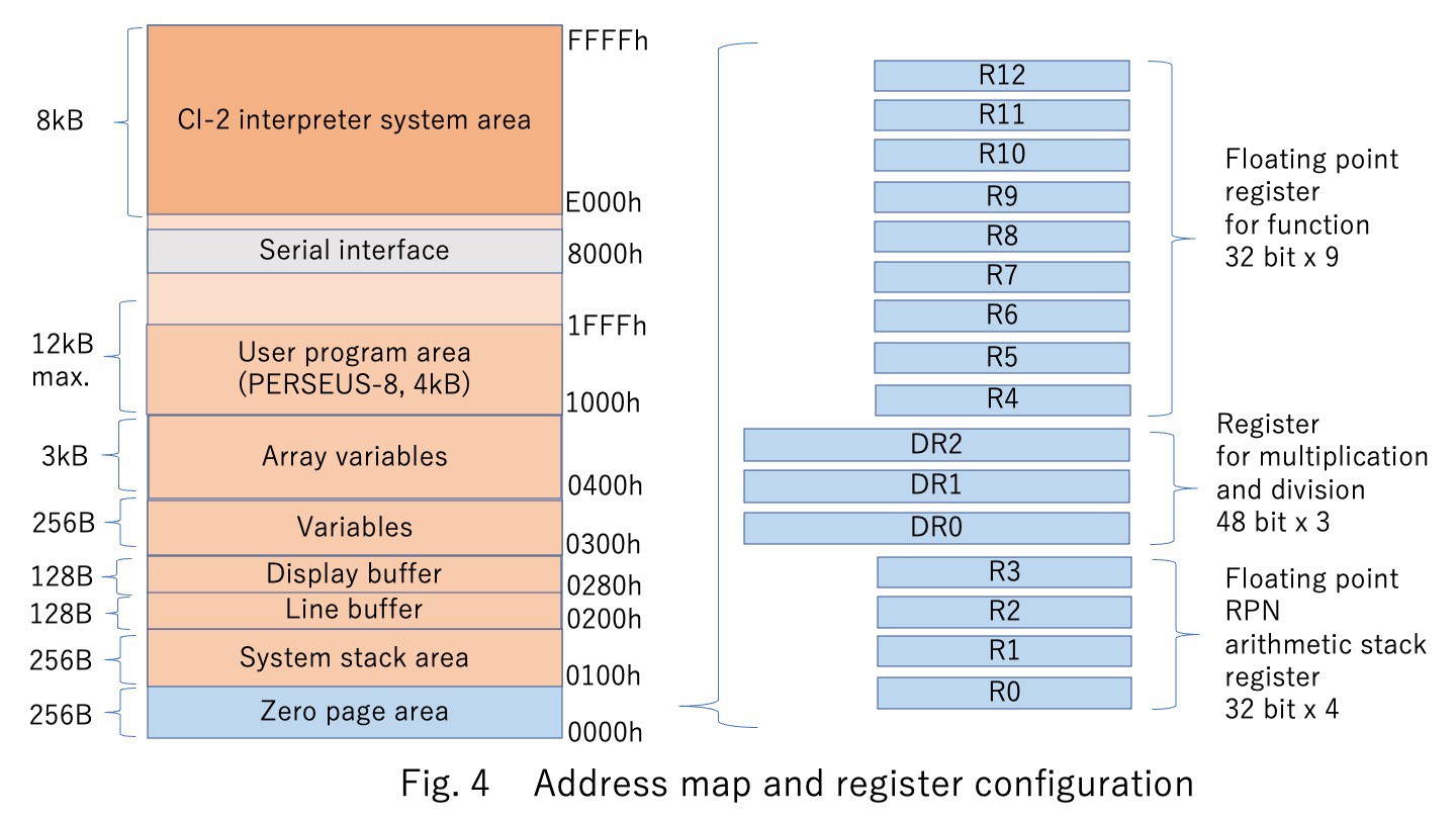
The RPN has a four-stage arithmetic stack, from R0 to R3, and operations of two terms are performed, for example, R0 = R1 + R0 for addition. The three 48-bit registers are used to calculate the mantissa for multiplication and division. In the case of the 24-bit mantissa section, the mantissa registers for multiplication need to be twice as large, 48 bits. The nine registers from R4 to R12 are used to calculate the elementary functions.
In addition and subtraction, it needs to make the exponent part of the two terms the same. It compares the exponential parts of R1 and R0, and change the smaller one to be the same as the larger one. The mantissa of a variable of the smaller exponent is shifted to the right to compensate. The mantissa part then converts the 24-bit absolute value and sign to the 32-bit complement, performs addition and subtraction, and then converts it back to absolute value and sign again. The reason for extending the bit is to ensure that the carry component is not missing. This ‘FLOATING POINT ADDITION’ process is mapped from address $ECC5 and ‘FLOATING POINT SUBTRACTION’ process is mapped from address $ECCF in the assembly code.
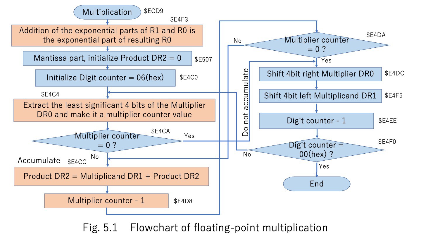
In multiplication, the mantissa part is stored in a 48-bit register, as shown in Fig. 5. The multiplication flowchart is shown in Fig. 5.1. At first, the exponent part 7 bits of the two terms are added.

For the mantissa part, the multiplier DR0 is shifted right and extracted 4 bits at a time, and the multiplicand DR1 is accumulated in the product register DR2 by the extracted number. The multiplicand DR1 is shifted to the left for each digit. This ‘FLOATING POINT MULTIPLICATION’ process is mapped from address $ECD9 in the assembly code.
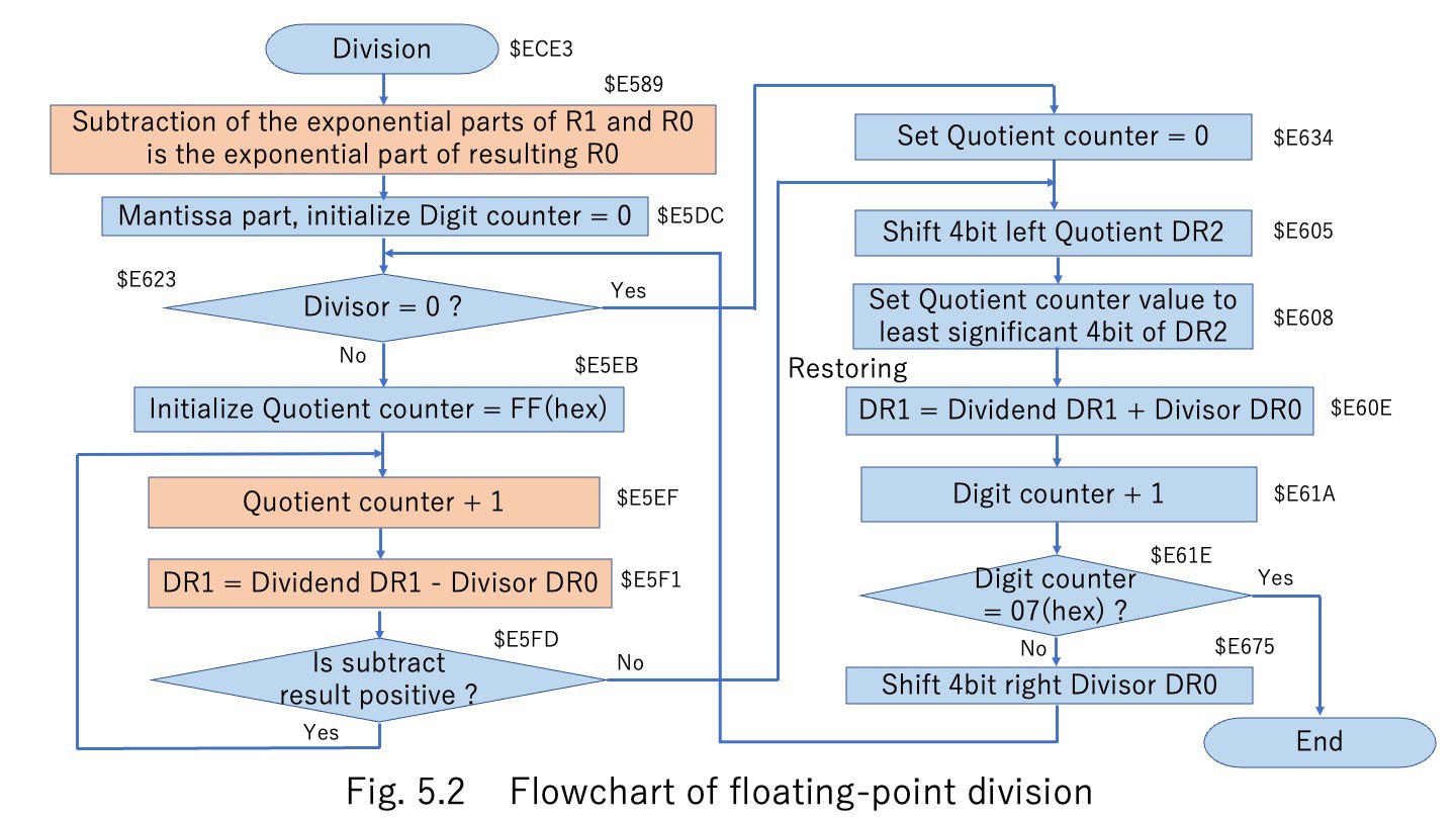
In division, the mantissa part is stored in a 48-bit register, as shown in Fig. 5. The division flowchart is shown in Fig. 5.2. At first, the 7 bits of the exponent part of the two terms are subtracted. For the mantissa part, the restoring division is used. The divisor DR0 is subtracted from the dividend DR1, and if the result of the subtraction is positive, the subtraction is repeated until the result becomes negative. When the result of the subtraction goes negative, the divisor DR0 is added once and the result is returned to positive. This number of subtractions is placed at the bottom of the quotient register DR2. For the next digit, the divisor DR0 is shifted four bits to the right and the quotient register DR2 is shifted four bits to the left in the same manner. This ‘FLOATING POINT DIVISION’ process is mapped from address $ECE3 in the assembly code.
6. Elementary functions
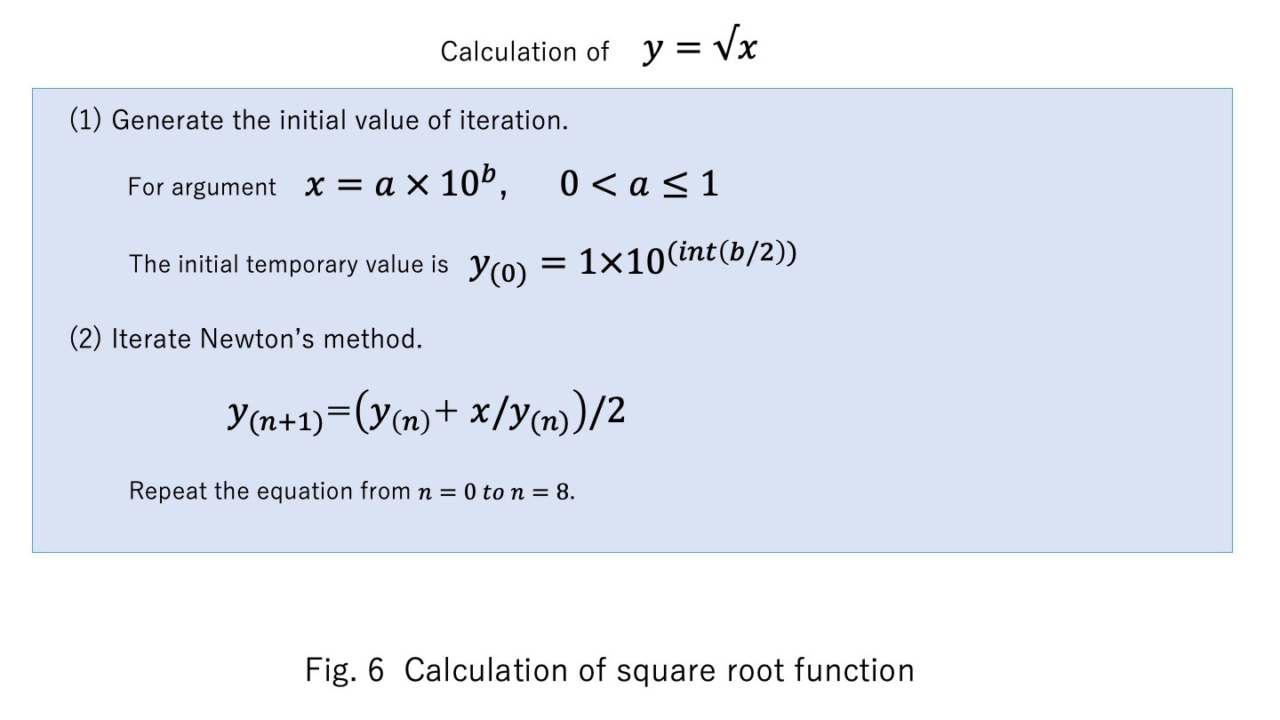
The square root function is calculated using Newton's method as shown in Fig. 6. To ensure fast convergence even with large numbers, an initial value of 1/2 of the exponential part of the argument is used. These processes are mapped from address $F0FF in the assembly code.
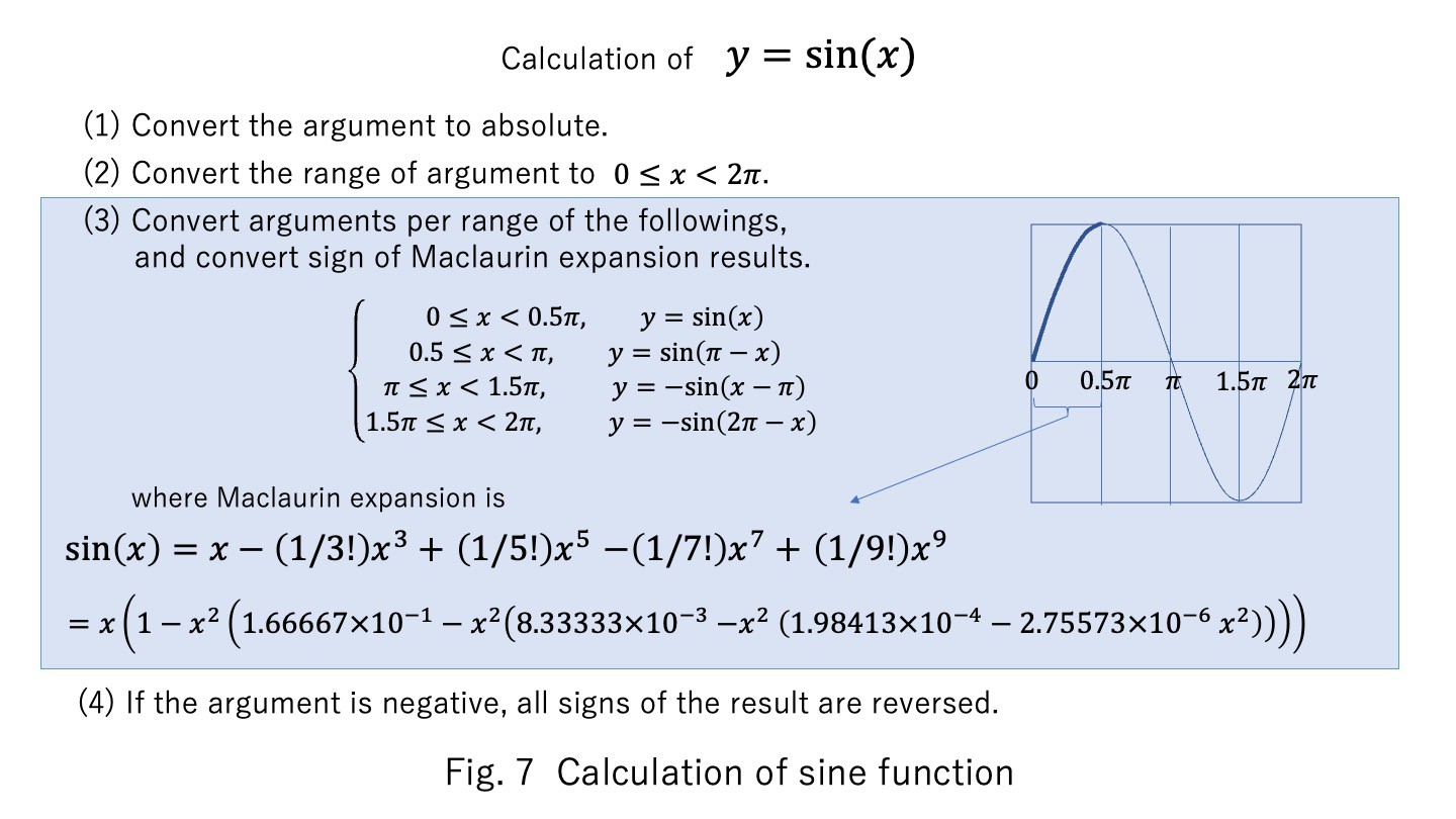
The sine function uses the Maclaurin expansion up to the ninth order shown in Fig. 7. The coefficients refer to the table. The arguments are transformed to be between zero and Pi/2, and the results are transformed accordingly. The cosine function is calculated as the argument of the sine function, which is the argument plus Pi/2. The tangent function is obtained by sine/cosine. These processes are mapped from address $F3B2 in the assembly code.
The arcsine function is obtained by the bisection method using the sine function. The arccosine is obtained by subtracting the arcsine function value from Pi/2. The arctangent function is obtained by the bisection method using the tangent function. These processes are mapped from address $F5F2 in the assembly code.
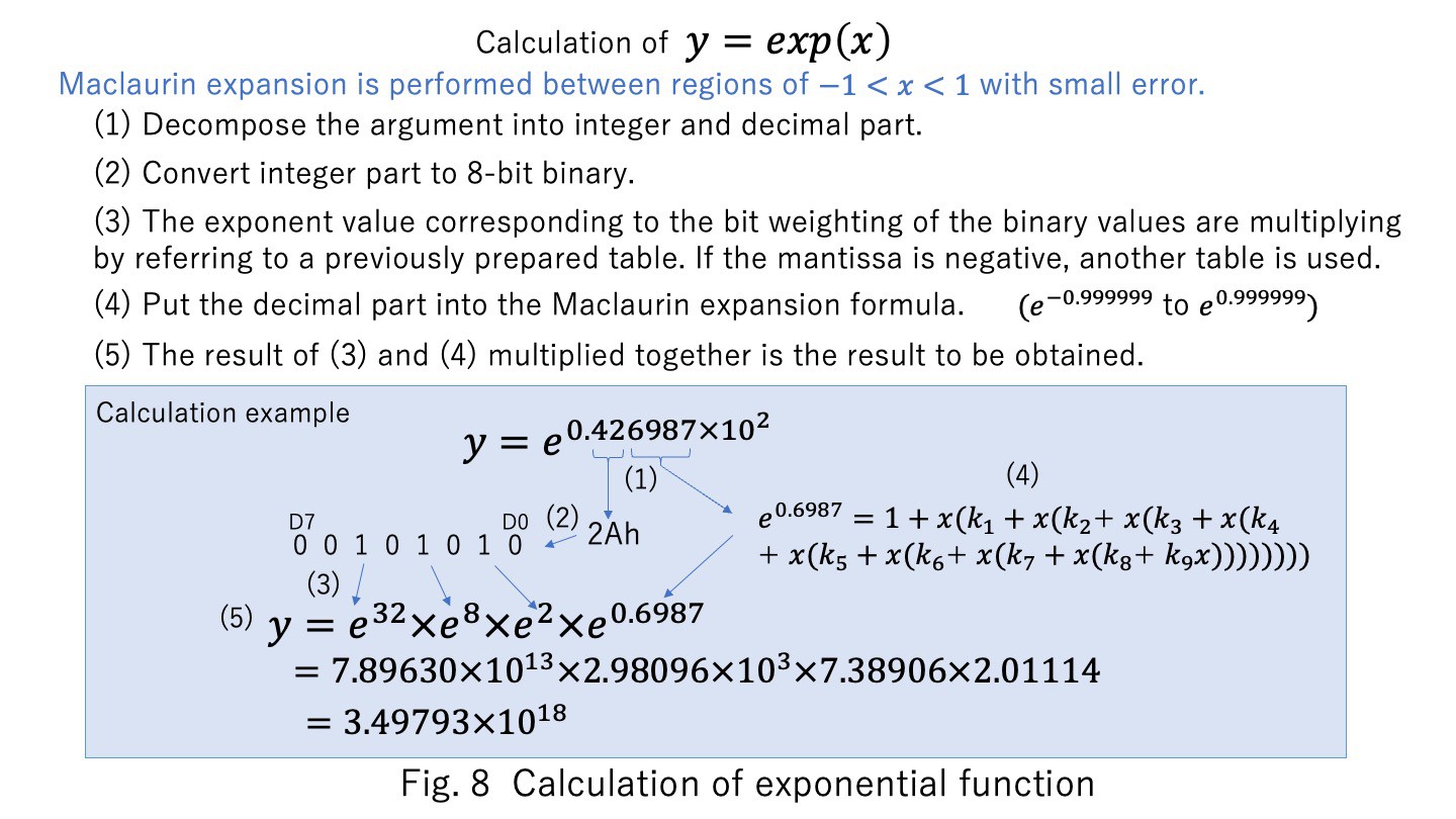
The exponential function is obtained by the Maclaurin expansion up to the ninth order. However, a good approximation is only possible when the argument is near zero. Therefore, as shown in Fig. 8, the function is decomposed into products of exponential values weighted by powers of two, and the fractional part. Only the fractional part is used as the argument for the Maclaurin expansion. These processes are mapped from address $F764 in the assembly code. The conversion table in (3) in Fig. 8 is from address $FFCC of the assembly code when the argument is positive, and from address $FF44 of the assembly code when the argument is negative.
The hyperbolic function is obtained using the exponential function. These processes are mapped from address $FAD4 in the assembly code.
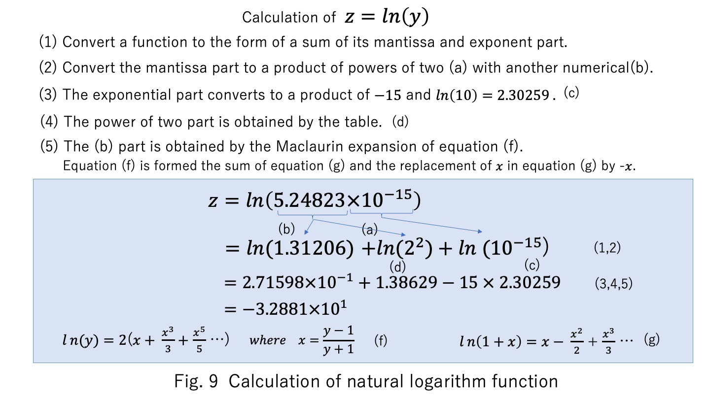
The natural logarithm function also uses the Maclaurin expansion up to the ninth order, but the function is decomposed into a sum of several terms so that the argument of the Maclaurin expansion is from 1.0 to 2.0. The other terms refer to the table. An example of the calculation of the natural logarithm is shown in Fig. 9. These processes are mapped from address $F875 in the assembly code.
A test program for each function value output for argument 0.5 is shown in the attached file ALL_FUNC_01.pdf.
7. Line editor
When a ':' code is entered following the first four digits of a single line input, it is automatically recognized as a line in the program and inserted into the program. If the same line number already exists in the program, the new line will replace it. If there is nothing after the line number and ':' code when a single line input, a line having that number will be deleted from the program. These ‘LINE EDITOR’ processes are mapped from address $E740 in the assembly code.
8. Program loading
As a function for loading multiple programs, commands are provided to load program text data from the outside into the user program area via a serial interface or parallel interface. In the case of RS232C serial interface, it is the ' “ ' command. This process is mapped after $F301 in the assembly code. Using this command, you can load the program edited on the external PC.
In the case of this 8-bit parallel interface, it is the ' ‘ 'command. This process is mapped after $F328 in the assembly code. This command can be used to load a program stored in the external PROM module EXTROM-2.
9. Development environment
This interpreter was developed by hand assembling. The machine codes were entered using the toggle switches on the front panel of the PERSEUS-8, and debugging was done using the single-step function for each routine up to about 200 bytes. I also inserted jump instructions in the program to trap the execution and examine the memory values. At runtime, the system area is switched to a write-protected state. This ensures that even if a bug causes the program to run out of control, the program will not be damaged.
Figure 10 shows an example of debugging: the 16-bit address toggle switches on the front panel of the PERSEUS-8 is 0010h, specifying the least significant byte of the mantissa part of the 32-bit floating-point register R0, and the 8-bit data LED displays 21 in BCD. On the other hand, the mantissa part of the result of the square root of 2 displayed on the serial terminal is 1.41421, and the two least significant digits match at 21. In this way, I can check the value of the internal register.
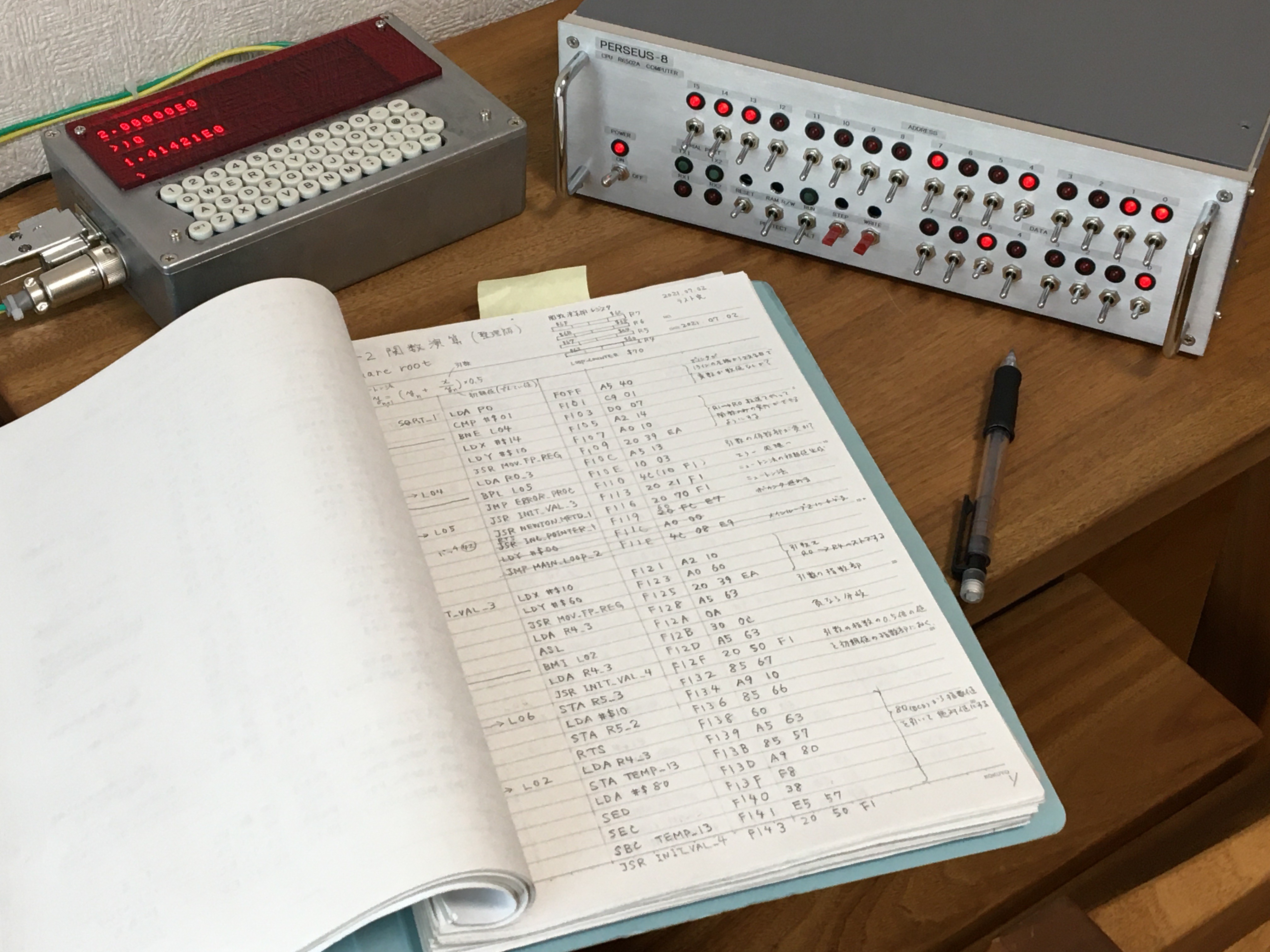
Fig. 10 Debugging while checking the memory value.
10. Current results
Currently, the code size of this interpreter shown in attached file (ASSEMBLY_CODE_CI-2_V2_0_0.pdf) is about 6.3kB. Of that, the sum of floating-point arithmetic and numerical input/output is 1.7kB, the analysis execution part is 1.7kB, the elementary function part is 2.4kB, and the editor part is 0.5kB. Since there is no error-determining function in the parser, the result of incorrect syntax cannot be guaranteed.
As for the accuracy of the floating point four arithmetic operations the six digits worked correctly. However there was no rounding by the guard bit, and it is truncated in this system. The accuracy example of the function was almost +/-4 at the sixth digit for the sine function. At first, I tried to calculate the function using the CORDIC (Coordinate Rotation Digital Computer) algorithm, but due to the reduction of significant digits during subtraction, I could not get good results, so I decided to mainly use the Maclaurin expansion for function calculation.
The arithmetic speed on the user program of this system was 2.0 ms for addition and 4.4 ms for multiplication, which is 1/100,000th of the execution speed of a standard personal computer made in 2020.
The obvious defects discovered between the release of version 1.1.0 in August 2021 and the present were that the square root function gave an error when the argument was zero and the calculation of functions for every 256 character position in the user program gave an error. The above defects have been resolved in the version 1.4.1 The defect of incorrect pre-addition and subtraction normalization for binomials with numerical values less than or equal to 1E-7 and zero was resolved in version 1.5.0 by modifying the exponential part of the numerical value zero to be the same value as the exponential part of the minimum value of 1E-39. In this version, the user program area limit can be set so that PERSEUS-9 can use a 12 kB user program area.
CI-2 version 2.0.0 added a command to load a program from an external PROM module.
11. Application example
As an example of application program, the FFT (Fast Fourier Transform)[2] which is a basic signal analysis process performed by the 1970s minicomputer to the latest PCs and the execution result are shown in Fig. 11 and the attached file (TEST_RAND_FFT_03.pdf). The upper of attached file is a 256-point signal generator, which has random number noise and sine and cosine wave components generated as a simulated signal and the next part is FFT program. From ‘GENERATE RANDOM NUMBERS + SIN COS WAVE’ are simulated signal data. And from ‘POWER SPECTRUM’ are FFT results of the signal.
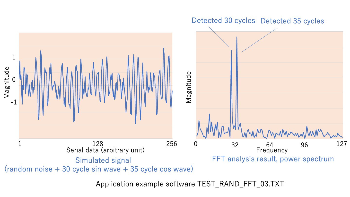
Fig. 11 Application example for signal analysis
Figure 11 left shows this simulated signal. In this example, a 30-cycle sine waveform and a 35-cycle cosine waveform are generated with a pseudo-random noise of the same amplitude, but the period is not clearly visible from the left figure.
The result of the FFT calculation of this signal is shown in the right side of Fig. 11. In this power spectrum display, it can be clearly seen that there are signals with 30 and 35 cycles. Since this interpreter does not have a drawing function, this figure was created by reading the numerical data on the terminal into Microsoft Excel.
The fact that the signal generation and analysis is done correctly proves that this interpreter is functioning correctly. The execution time was 240 seconds for this 256-point FFT.
The linked video "Homemade Floating Point Interpreter computes FFT" demonstrates the execution of an FFT with 32 points.
12. Demo video
In the Following video 1, I will demonstrate arithmetic operation and natural logarithm functions in CI-2's direct mode. In the program execution mode, I run a sample software program with exponential functions. It also shows how to add a line to control the execution of the program using a pointer variable. There is no audio explanation, so please turn on the subtitles to watch.
Video 1 Arithmetic operation, natural logarithm function and exponential function
Video 2 below shows an application program CALC_PLANET_POSITION_02_5_3.TXT that calculates the position of planets. The program finds iterative approximate solutions to the Kepler's equation from the orbital elements of the planet and converts the planet's vector elements to right ascension and declination. This calculation makes extensive use of trigonometric and inverse trigonometric functions, so it also serves as a validation of these functions. This program is executed on PERSEUS-9, which implements CI-2 in ROM as described below. The program is loaded from an external PC via a serial interface using the CI-2 program load command.
Video 2. Running an application program to calculate the position of a planet
13. Making ROMs of the interpreter
The interpreter is running on the computer's battery-backed RAMs, but it can also run on ROMs. The programming to the ROMs was done using the programmer presented in my other project Fully manual PROM programmer, which uses four D2716 type 2 kB EPROMs to store the entire interpreter in an 8 kB capacity. The entire programming process took 20 hours manually. Figure 12 shows how the programmed ROMs are mounted on the computer PERSEUS-8.
In March 2023, a PROM programmer shown in Fig. 12 was successful made that can be automatically programmed by the interpreter's user program process, so PROMs can be revised in this way from version V.1.5.0 onward.
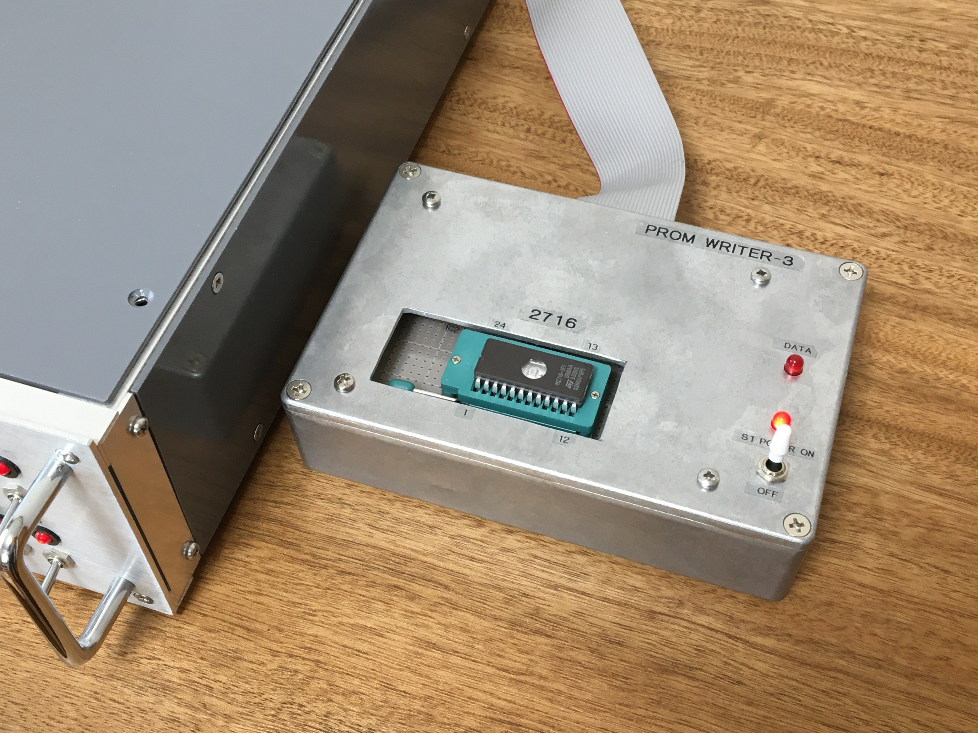
Fig. 12 Homemade PROM programmer connected to the parallel interface of PERSEUS-8
The following video 3 shows how this PROM programmer is used to update the interpreter. There is no audio explanation, so please turn on the subtitles to watch.
Video 3. Updating the interpreter by using the PROM programmer
Figure 13 shows how the programmed ROMs are mounted on the computer PERSEUS-8.
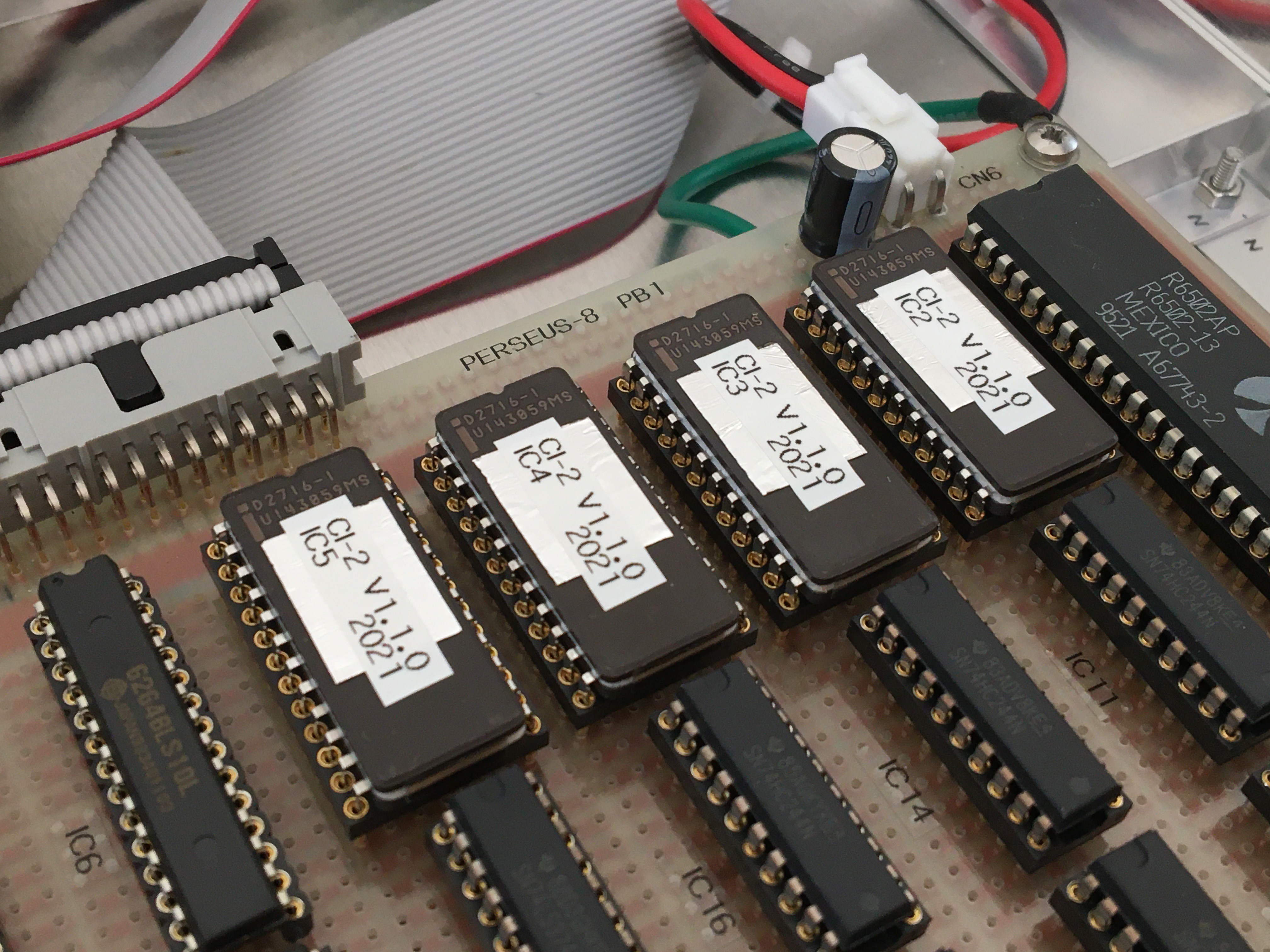
Fig. 13 ROMs of the interpreter
Whether the interpreter is executed in ROMs or RAMs is switched by a toggle switch on the board. When running in ROMs, the single step operation mode of PERSEUS-8 with a system clock of 2 MHz will not work. This is because the access time of this PROM is slow at 450 ns compared to 100 ns for SRAM. The highest operating clock for single-step operation in ROM mode was 1.5 MHz in the experiment.
On the other hand, the maximum operating clock for RUN operation in RAM mode was 4.5MHz, which was 2.25 times faster than the R6502A datasheet value of 2.0MHz. However, this evaluation is not an experiment that takes into account individual device differences or ambient temperature.
References
[1] MCS6500 MICROPROCESSORS PRELIMINARY DATA SHEET, MOS TECHNOLOGY, INC. MAY, 1976.
[2] Steven W.Smith, The Scientist and Engineer’s Guide to Digital Signal Processing, California Technical Pub, 1997.
(Posting date Aug. 06, 2021)
(Rev. Aug. 01, 2023)