Front panel
This stage of the project started with assembling the top (front) panel. Firstly, I pasted the vents and fans. Then screwed the antenna holders to the wifi adapters through the panel. Installed the power switches for each wireless adapter, and then the threaded SMA connectors that receive the antennas. The main display was put into place using 4 screws and the printed frame. The small display was then pasted into place. All the cables that had to go through to the bottom stack were routed through the cable passthrough cutout.
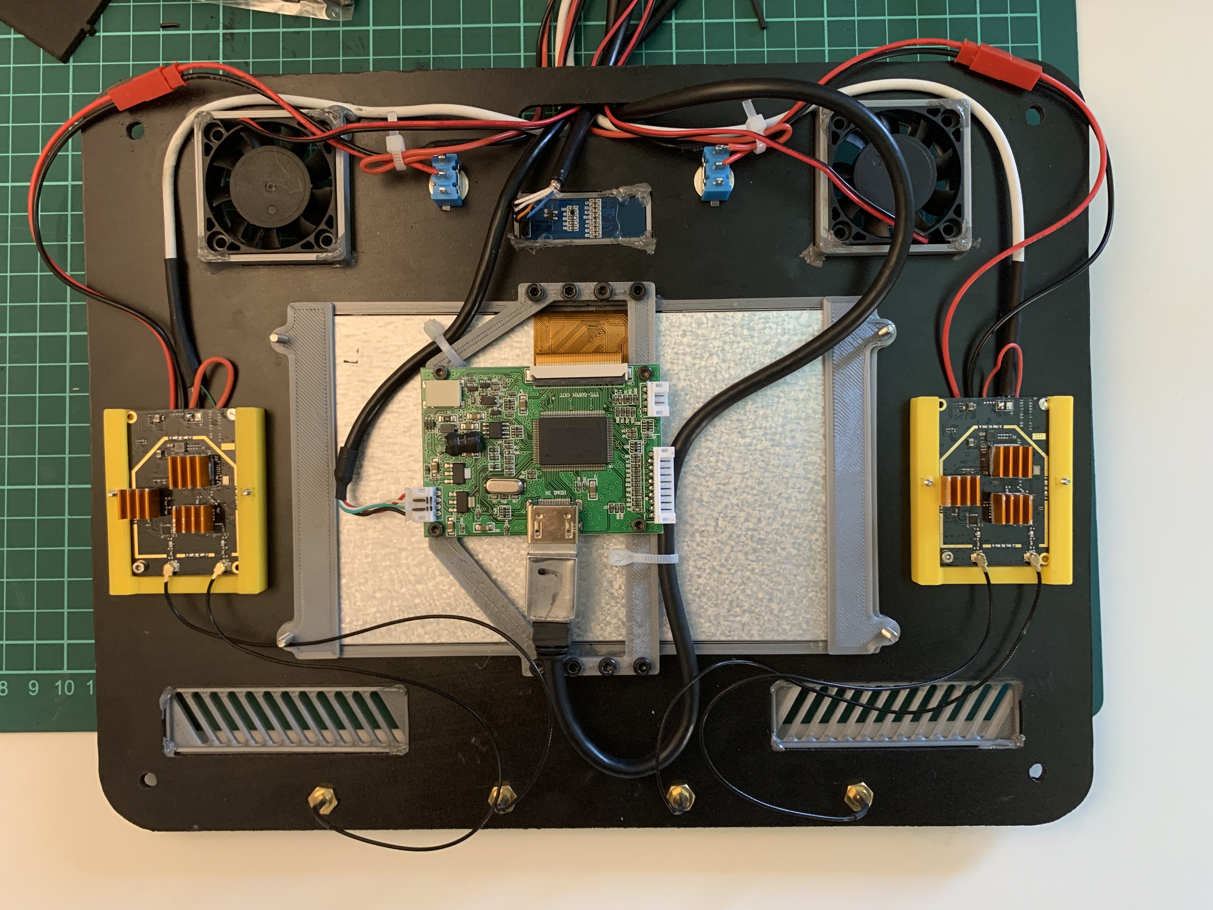
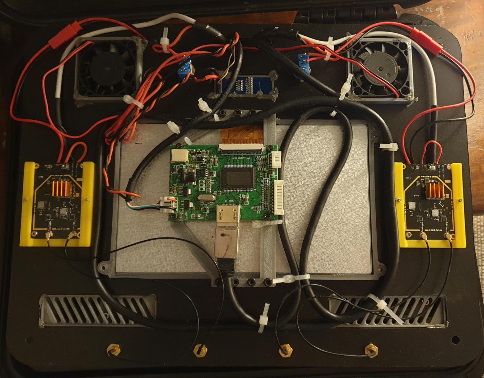
You can see (top to bottom) the two cooling fans, power switches for the wireless adapters, the mini display, main display at the middle with its respective controller, the wireless adapters with their yellow frames to the sides, the cooling vents and the SMA antenna connectors.
An interesting comment on the HDMI cable. I wasn't able to find a cable with small connectors and short (~30cm). Of course I had to use the length available, but for the connector issue, I stripped the rubber part that covers the connector housing. The excess cable was then winded around the screen and left behind the front panel instead of winding it and leaving it inside the stack. I consider that leaving it behind the front panel makes better use of space.
Bottom stack
The bottom stack was made in a top down manner. I started placing the components (screwing and pasting) on the top panel and worked my way down.
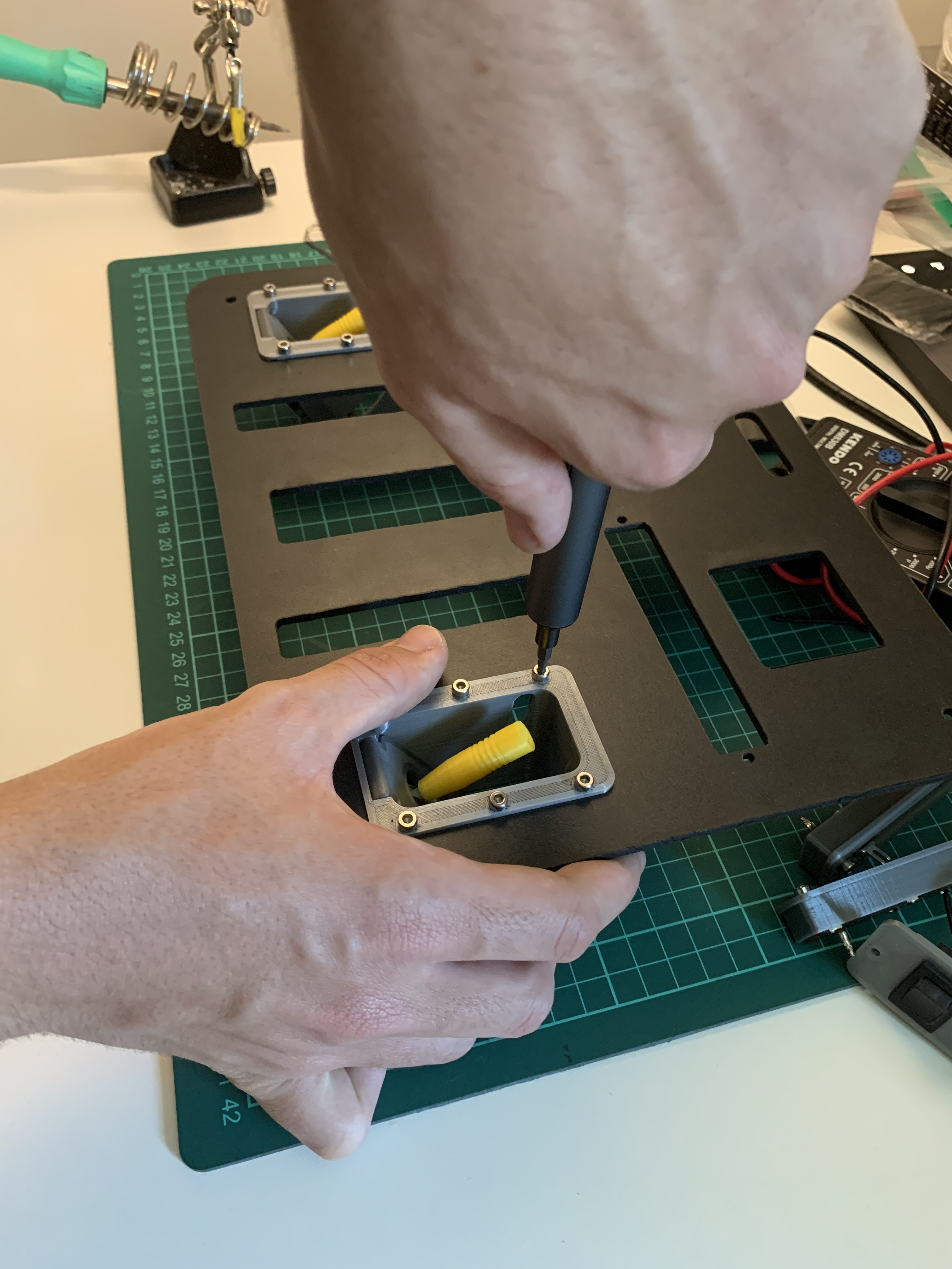
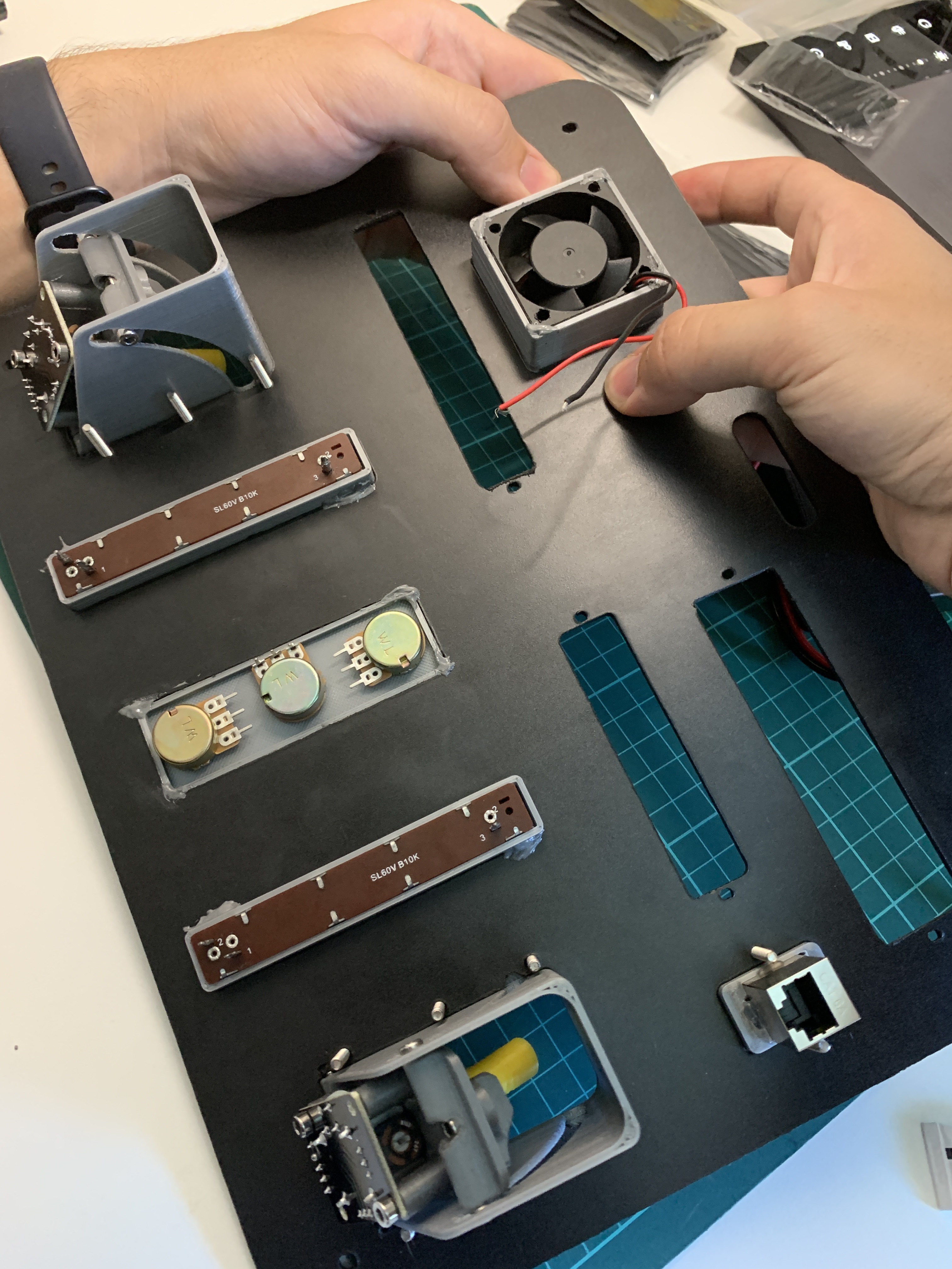
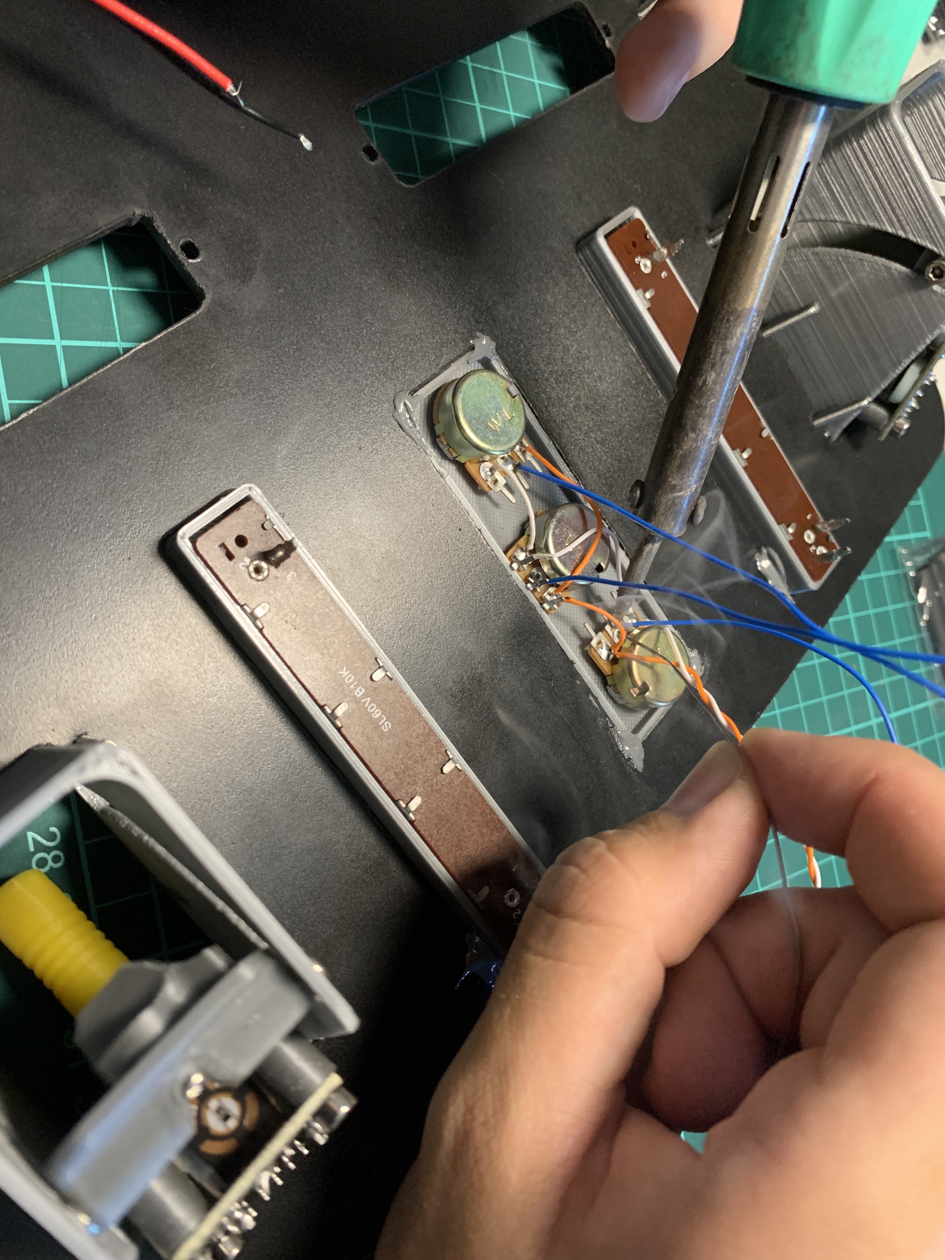
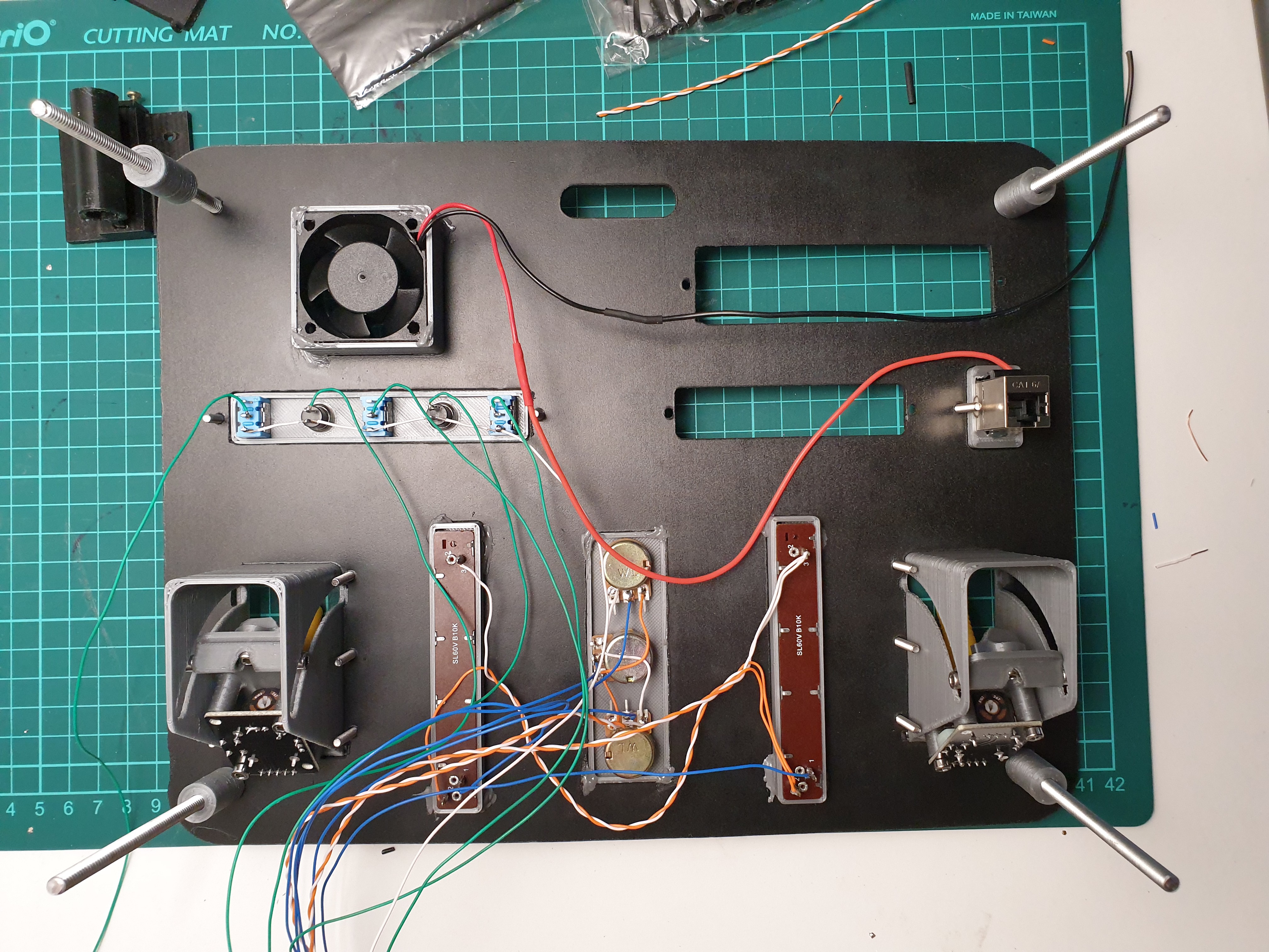
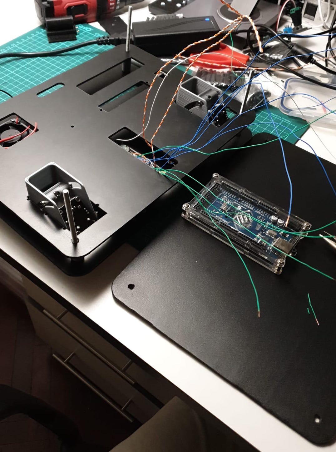
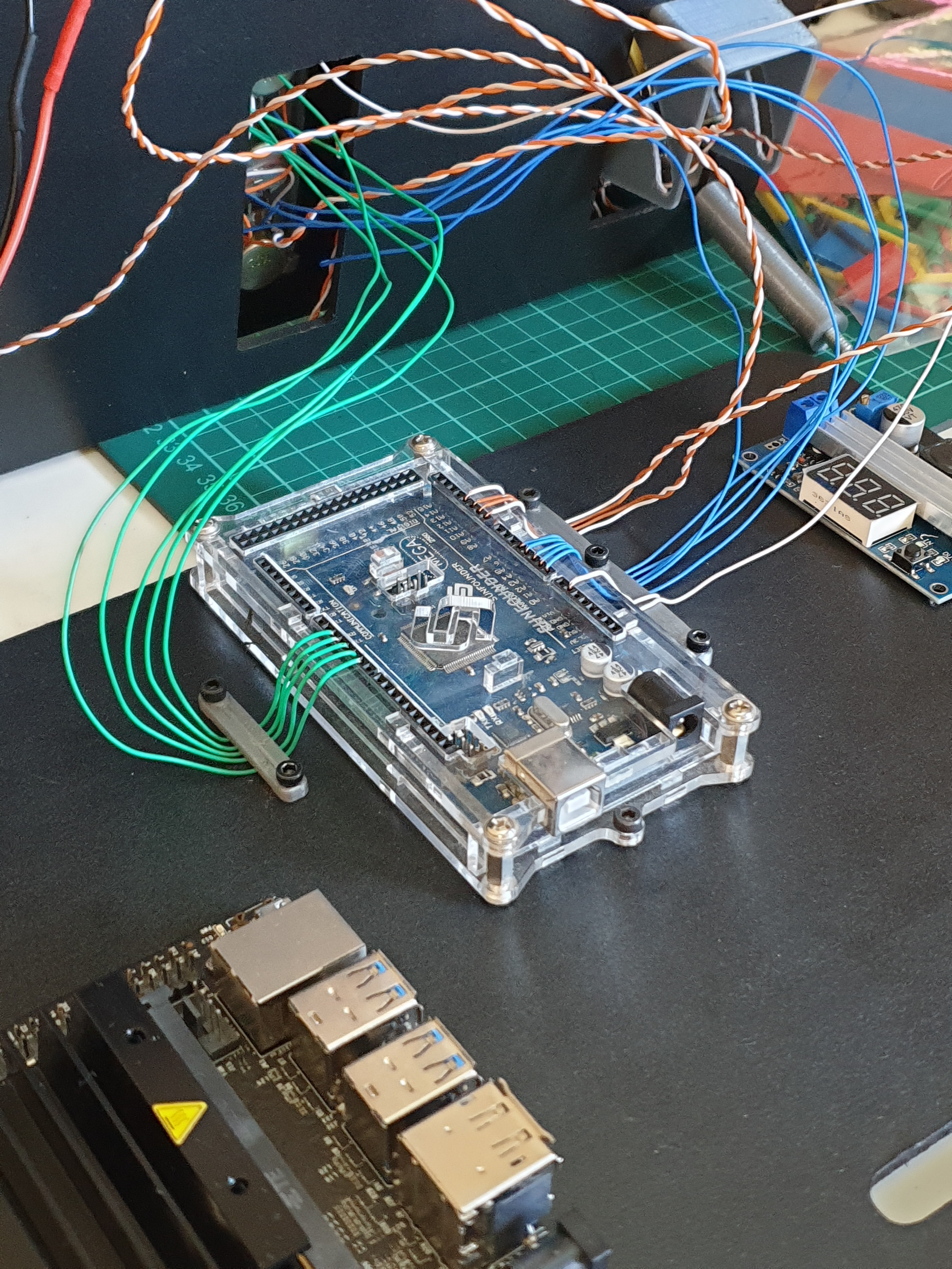
Everything seemed to be coming out great. Or did it? I really didn't like the look and lack of modularity this bunch of cables brings in. When assembling the stack, there would be quite a handful of cables struggling to go somewhere. I want this to be easily serviceable and this prevents that from happening. If I had to disassemble the stack, I'd have to mark down every cable to know where it was connected. I'm thinking some modular connectors. Maybe can recycle some old IDE connectors? Or maybe make my own?
 Maximiliano Palay
Discussions
Become a Hackaday.io Member
Create an account to leave a comment. Already have an account? Log In.