Close

3D printed stack connectors

A project log for Robotics Ground Control Station

Yet another overkill project. An attempt at building a portable and versatile GCS for robotics.

maximiliano-palayMaximiliano Palay 11/05/2021 at 21:240 Comments

As I explained in the last log, when assembling the bottom stack I realized the cable management was poor between the top and bottom panels. The serviceability and ability to make changes would be limited by such design. At first, I started looking throughout my stuff for any modular connector that could be incorporated to the panels. The main signals to go through these would be the sensor inputs to the Arduino. After going through many ideas, I settled on making my own connectors. Why not some experimentation too? That's part of what this is about!

Maybe this log deserves to be a whole separate project, but the motivation for making these connectors was the RGCS.

I had some 0.2 mm nickel strip for building lithium ion packs, that seemed to make a good contact surface. The tricky part was how would I get to hold the strips in place. So I made a quick design and printed a test.

This looked promising!

I still had to figure out how the strips would be held in place. Due to the size of the strips (and I didn't want to cut them  longitudinally) and the limited ability to hold them down firmly, the connectors had a nice gap in between contacts.
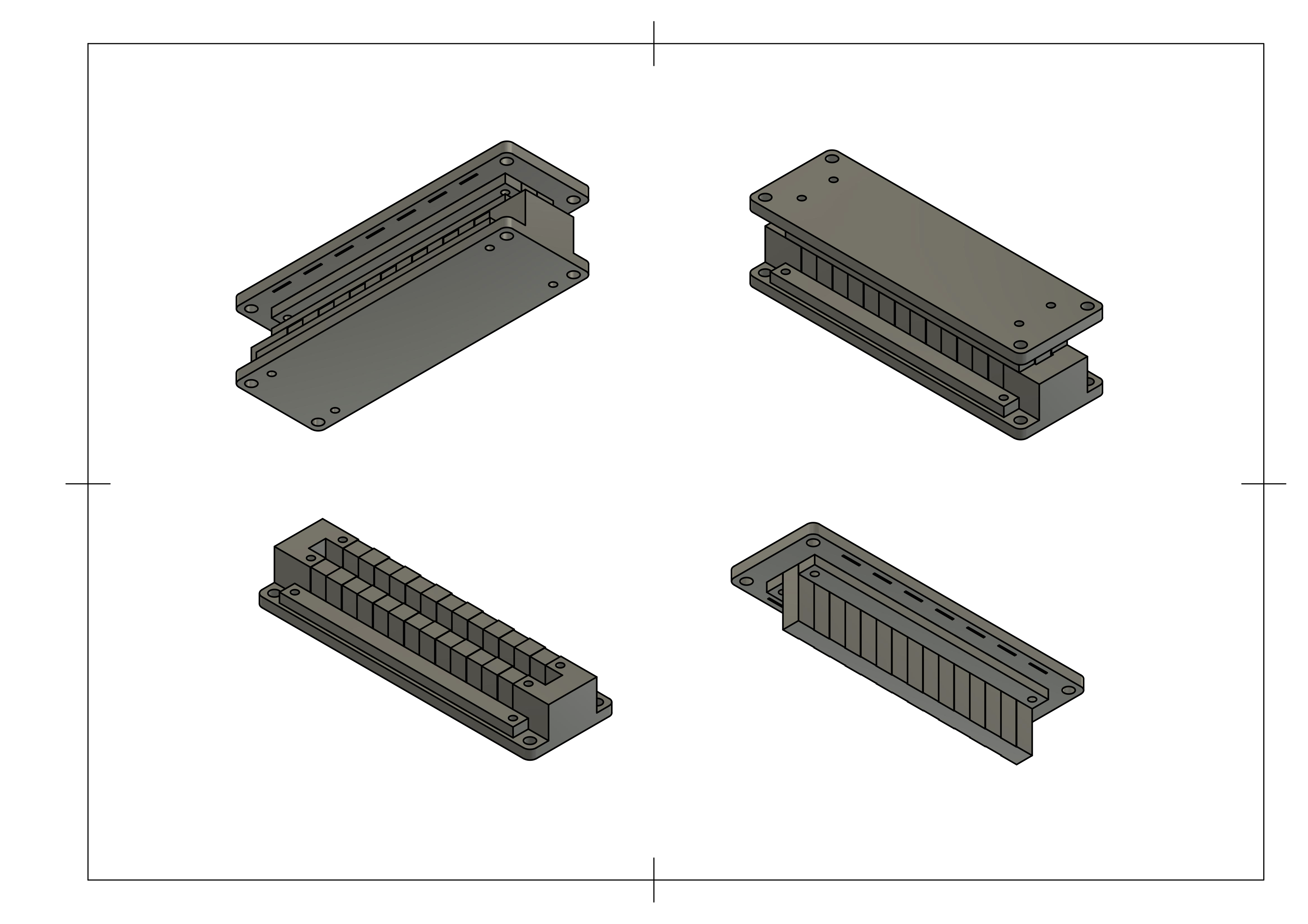
Views of the CAD model of the connectors

Each connector part (m/f) consists of 3 pieces. A main piece where the contacts are placed, and two plastic strips that are screwed down on top of the nickel to hold it in place. You might get a better idea when seeing assembly pictures.
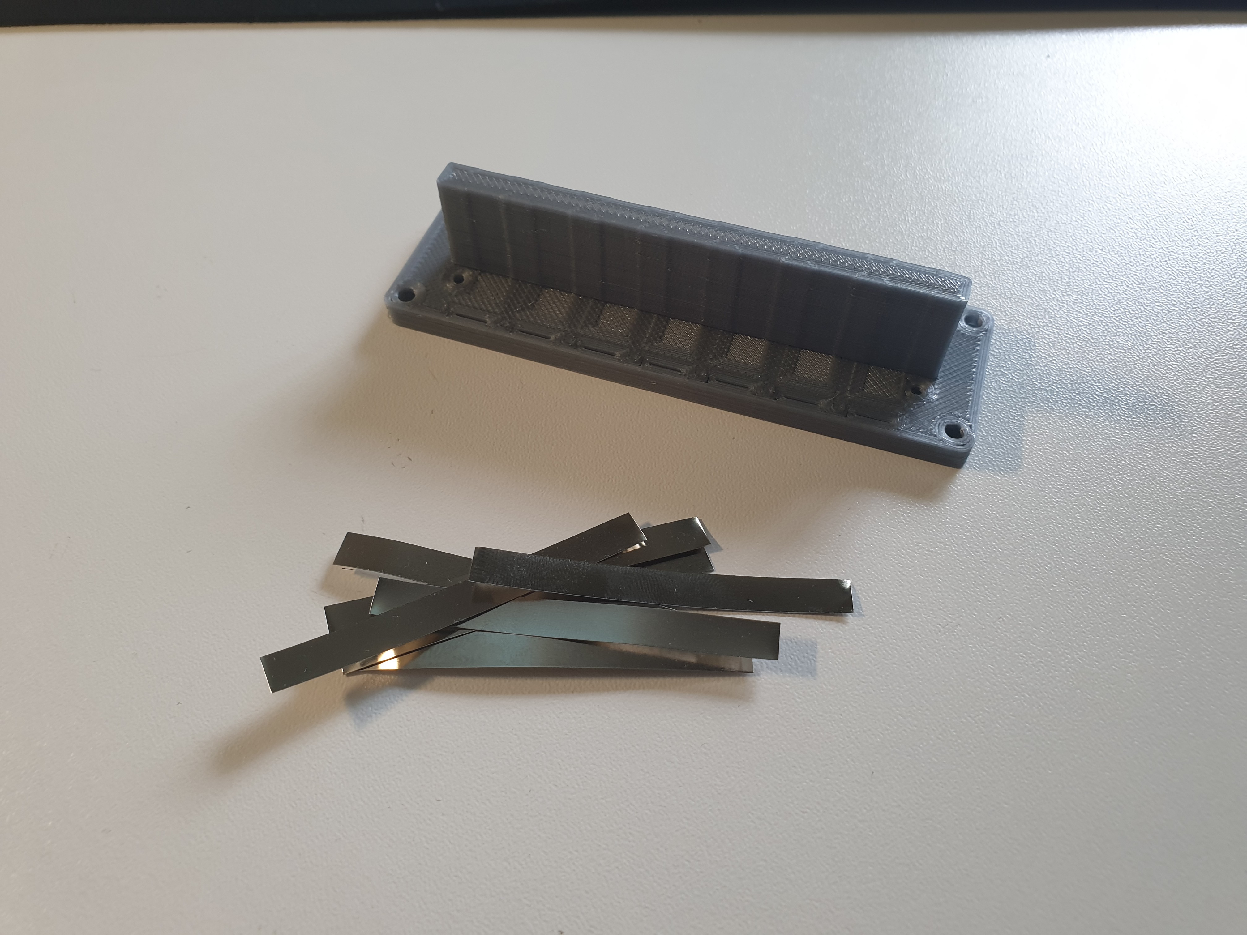
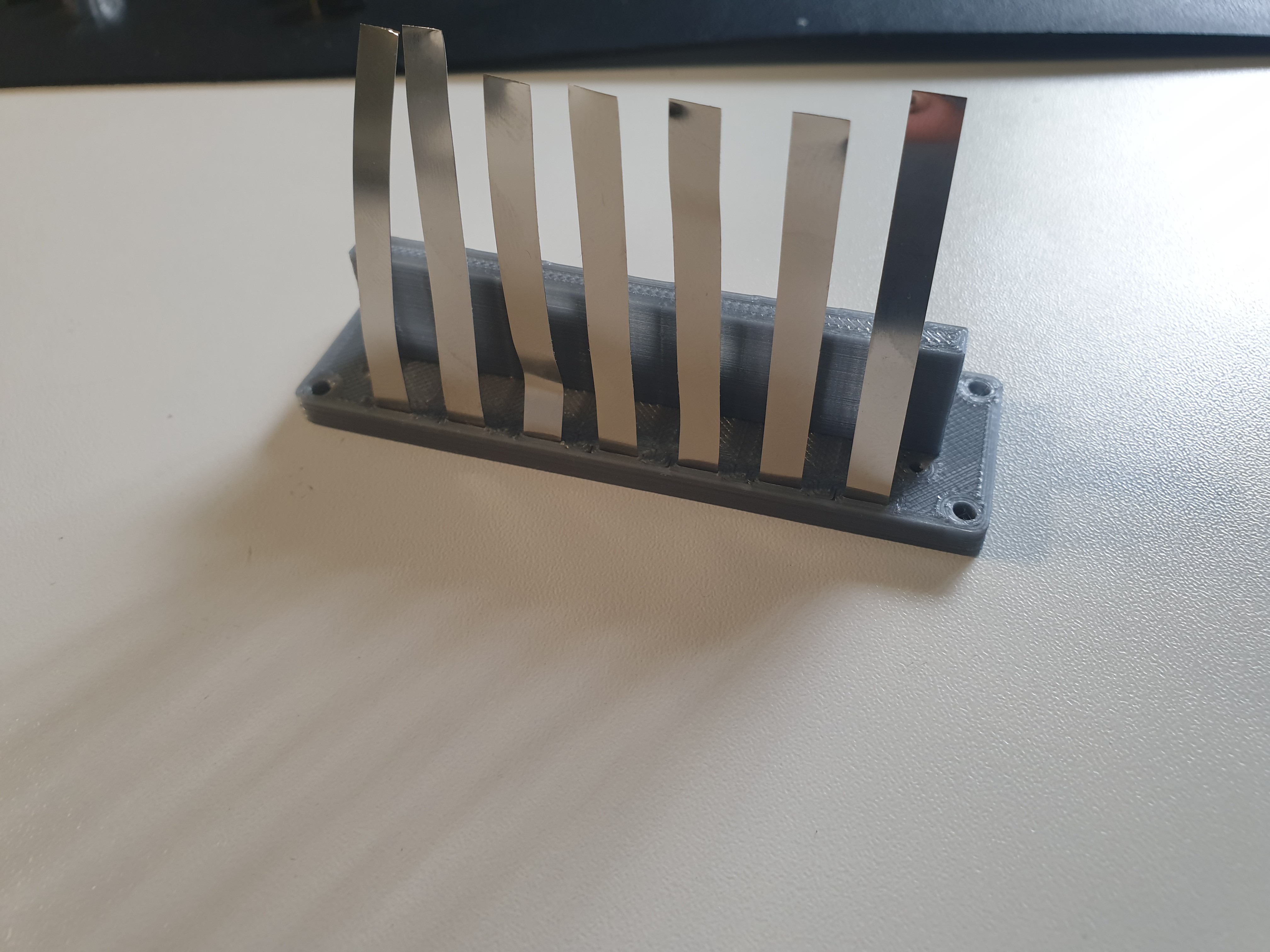
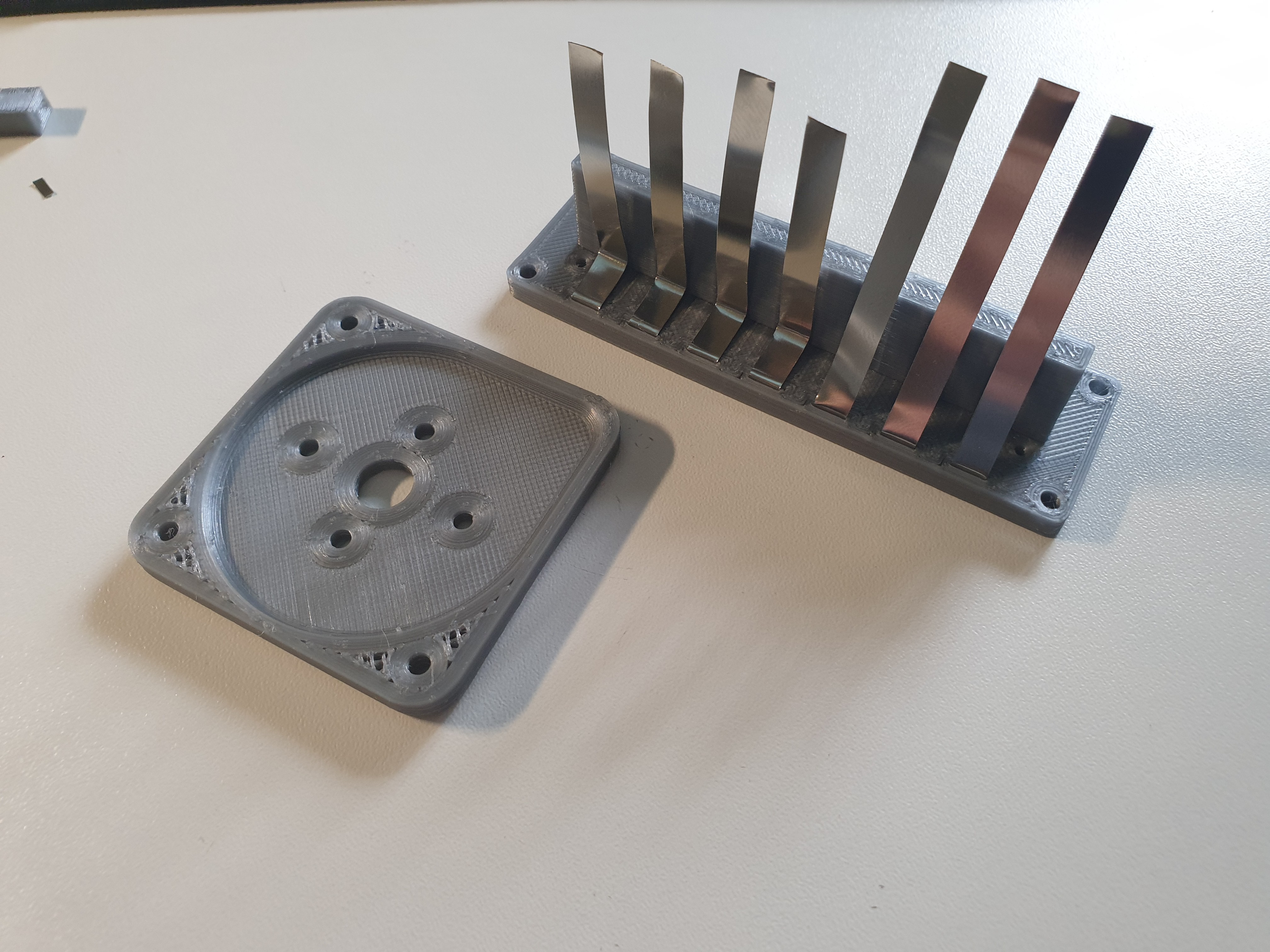
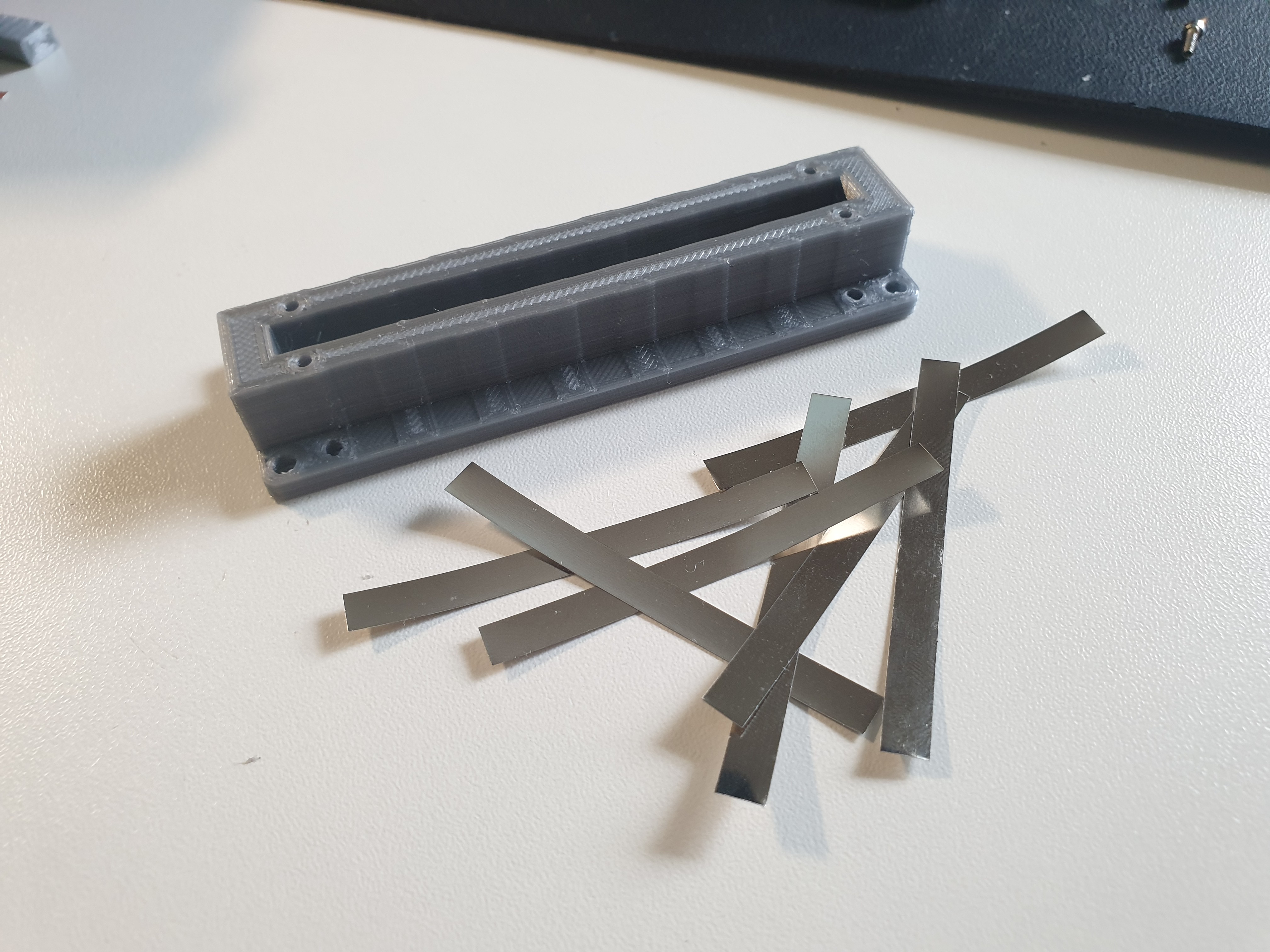
3d printed M connector and nickel strips cut to length, ready to be assembled.
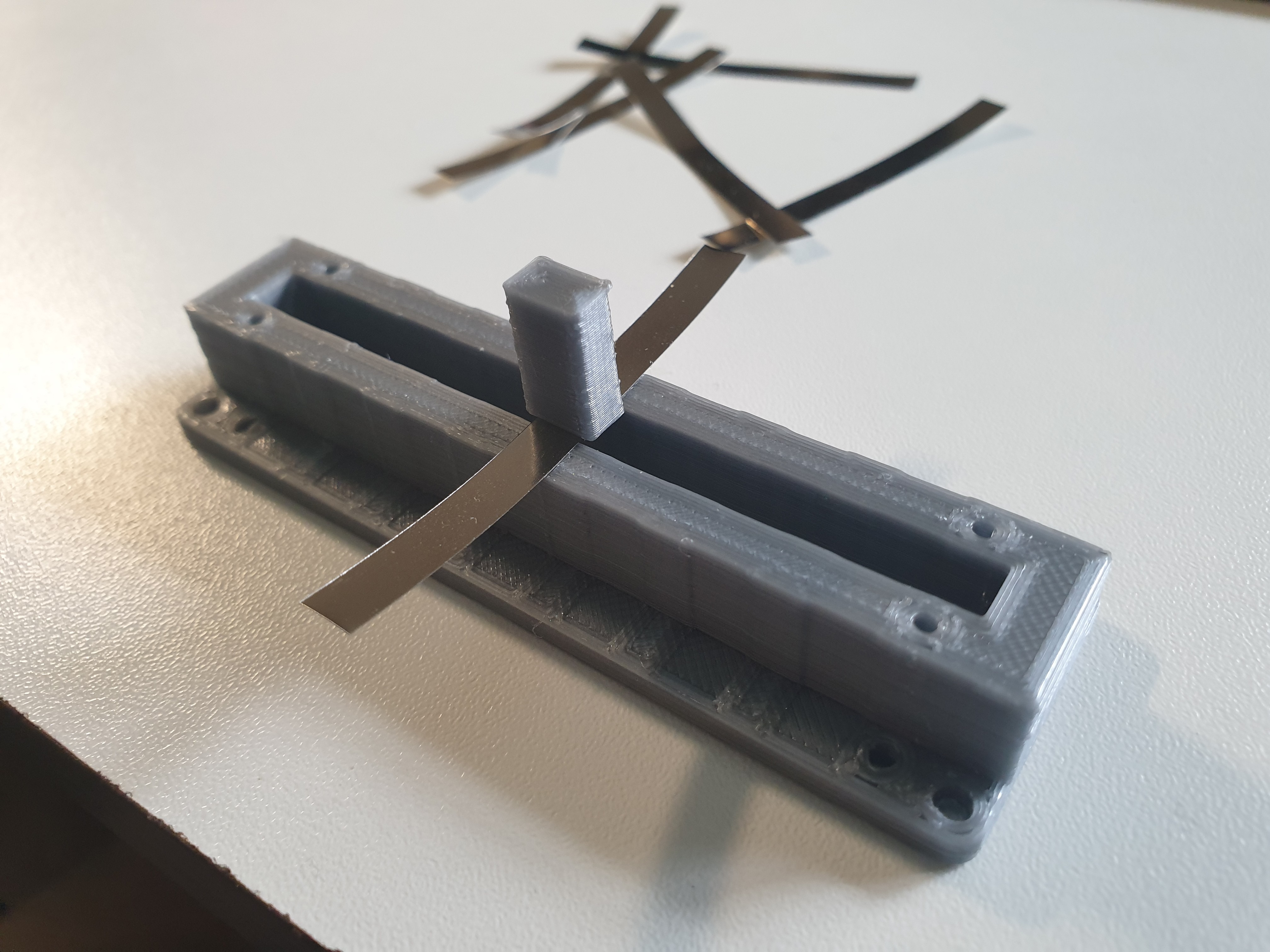
Placed the strips into the cutouts
Helped by a tool that had an angle (anything small enough and with a 90degree angle should work), firmly marked the bends.
Helped by a scrap 3d printed part that had an angle (anything small enough and with a 90degree angle should work), firmly marked the bends.
Placed the 3d printed strip to hold everything in place.
Placed the 3d printed strip to hold everything in place
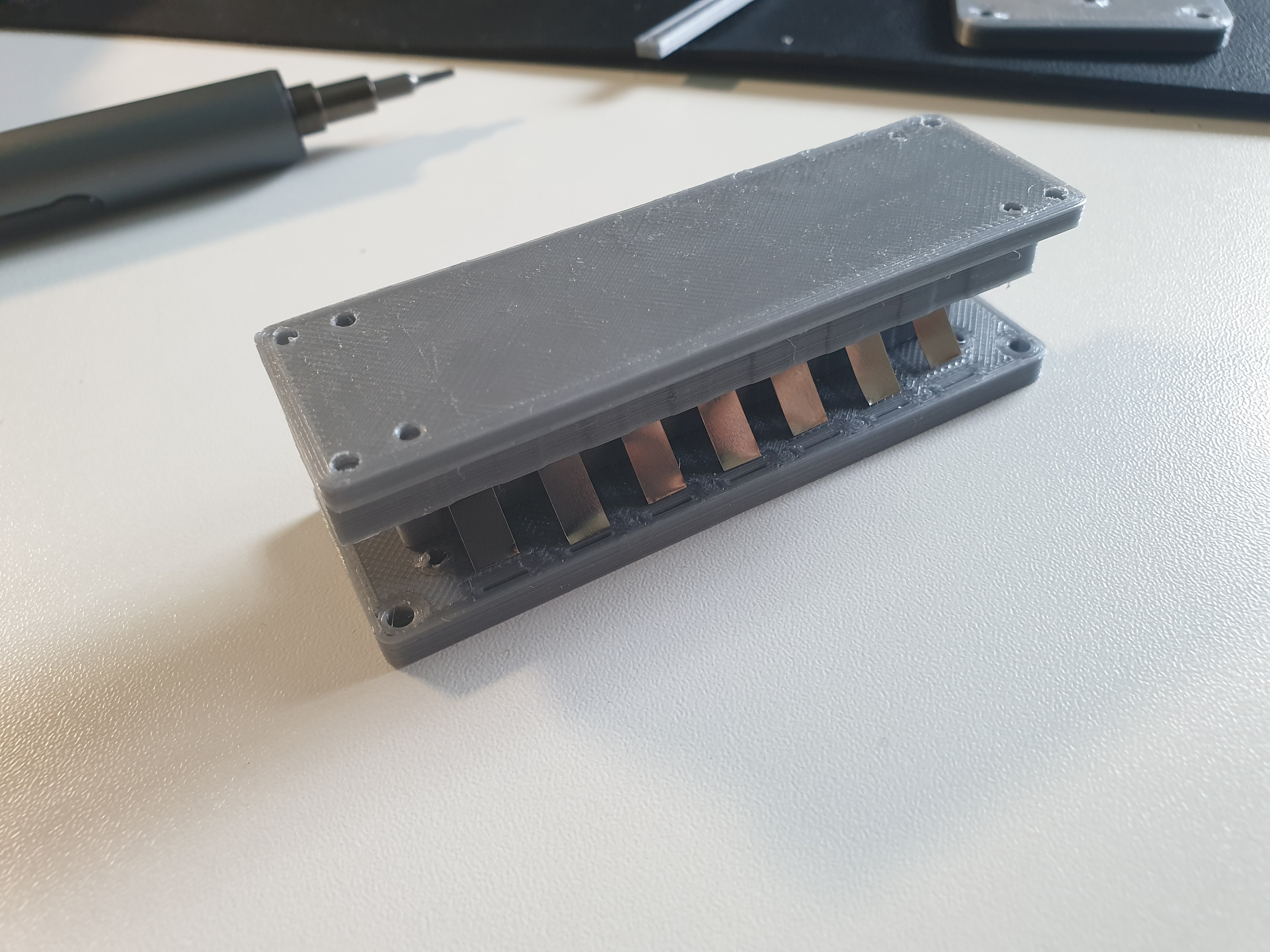
Inserted the M connector into the F connector just as it was on the previous picture to make the bends naturally with the receiving part.
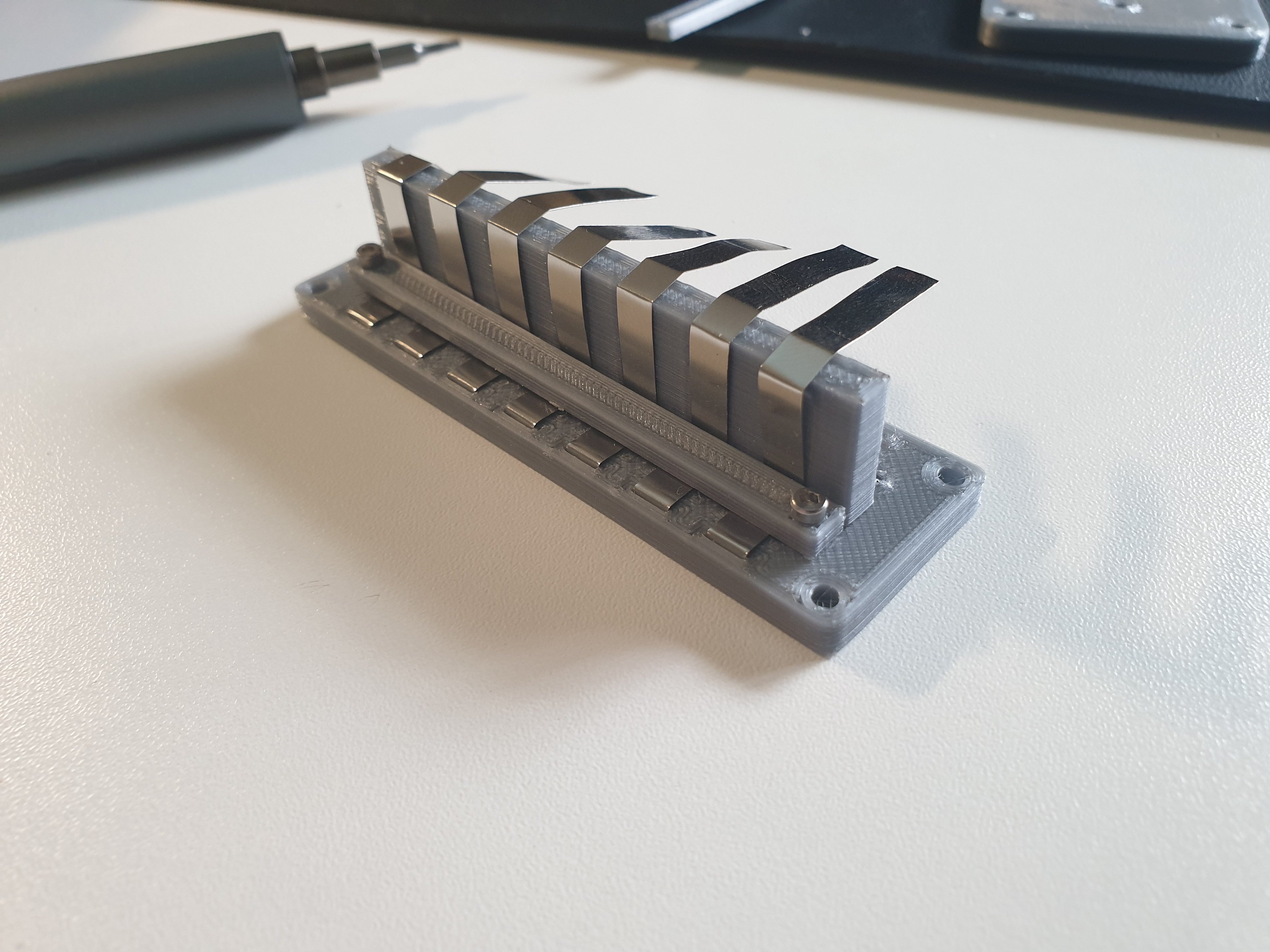
Marked the remaining bends with the tool and secured the strips finally in place. M connector finished!
The F connector was assembled in a similar manner.
The F connector was assembled in a similar manner. Here you can see the3d printed piece and the strips cut to length.
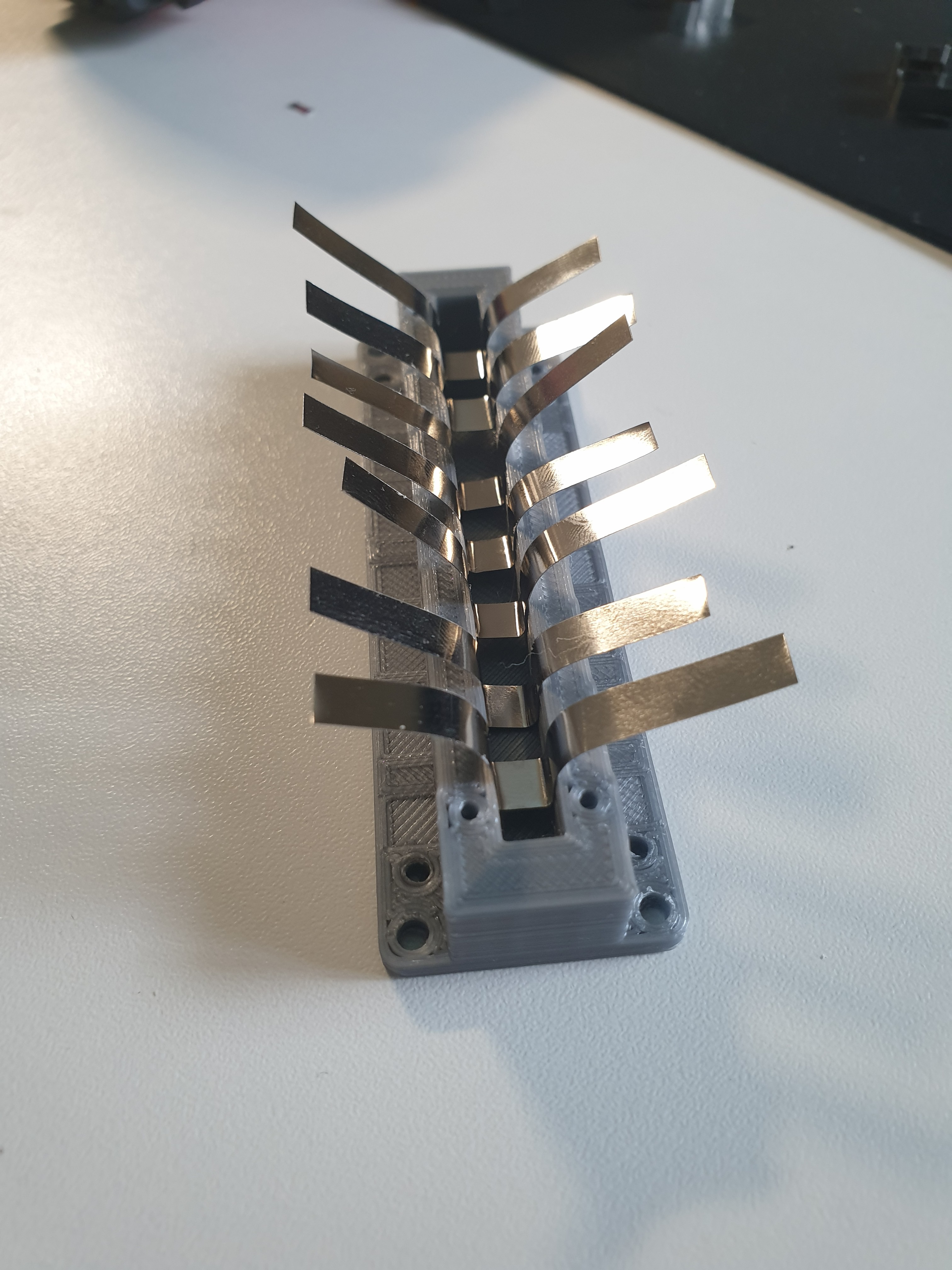
Placed the nickel strips in position and firmly pressed them in with an auxiliary 3d printed tool that had the same width as the M connector.
Placed the nickel strips in position and firmly pressed them in with an auxiliary 3d printed tool that had the same width as the M connector. 
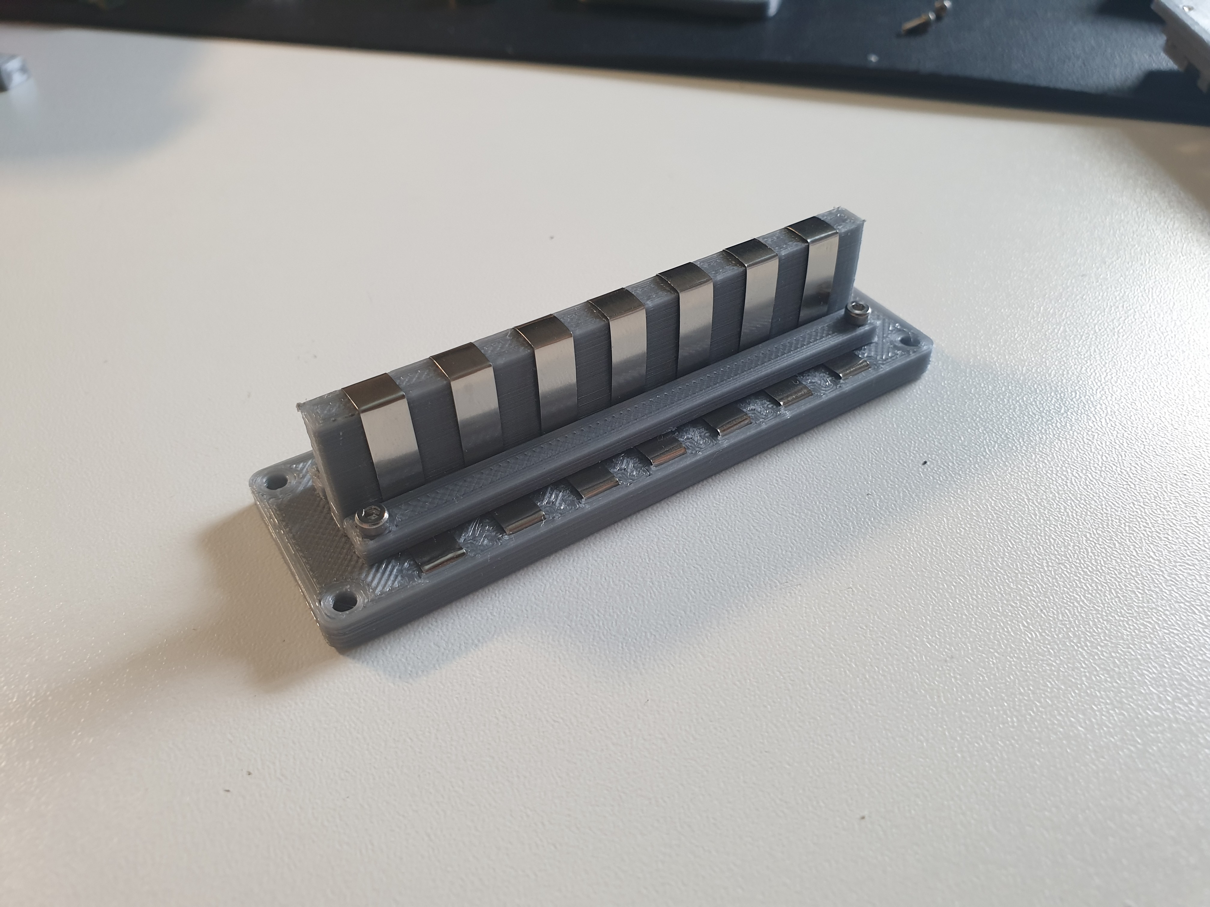
Then marked the bends with the same tool previously used and secured the contacts in place with the plastic 3d prints plastic strips.
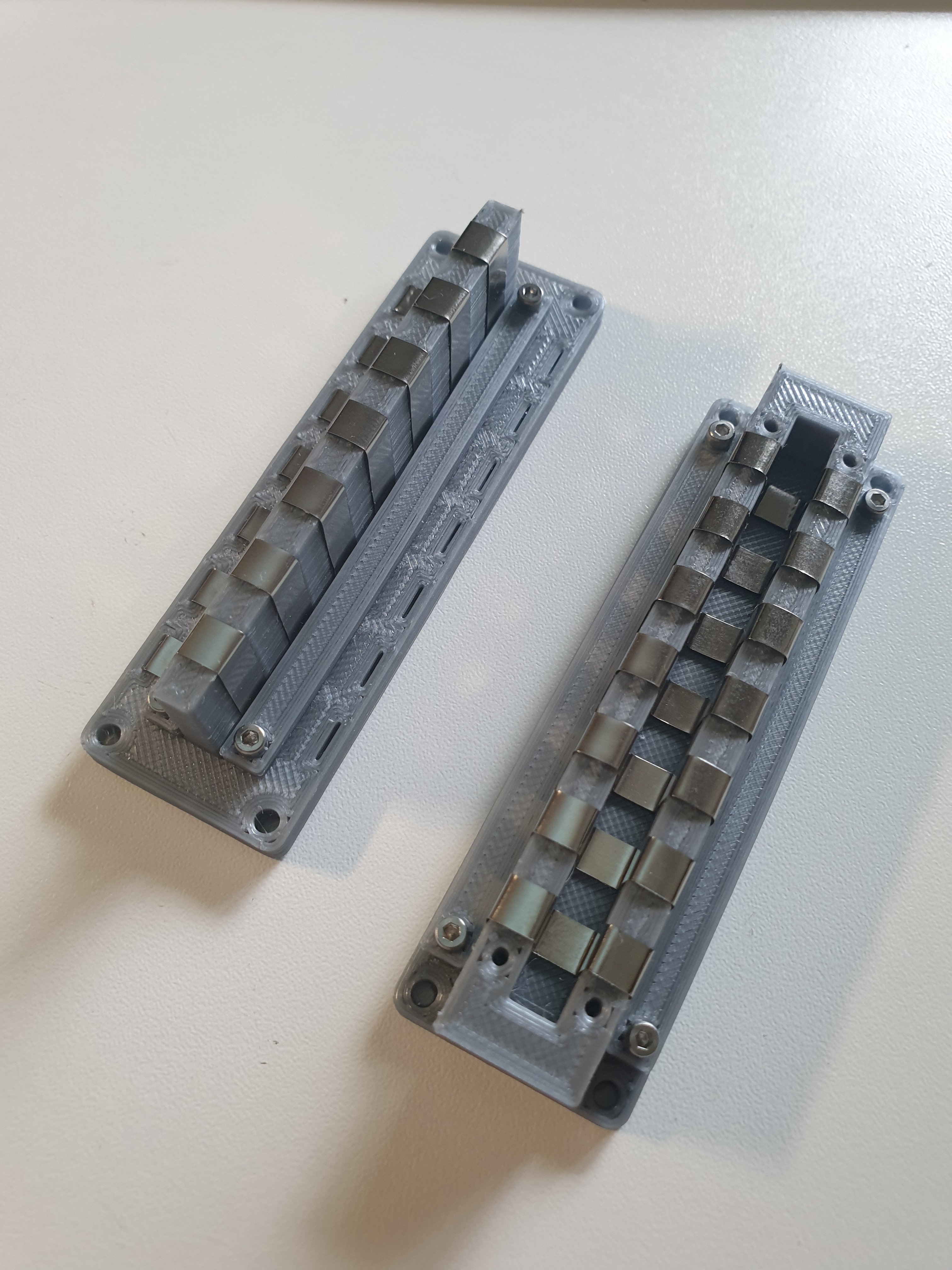
Mostly finished M and F connectors! The F is missing two plastic strips that were later added for securing the nickel strips in place.

Discussions