 Albert Gonzalez
Since the last time I made something synth related (this Atari Punk Console inside an alarm proximity sensor case - my first approach to this world, btw) I've been interested on knowing more about the electronics behind all those full synths and modules people made and share.
Following that idea, I've poked around, read a lot and watched some cool videos from people that really know what they're doing (exactly the opposite as me! : D) until I finally made one of those "classic" sequencers according to the Internet: a 4017-based Baby-10-like attached to an Atari Punk Console.
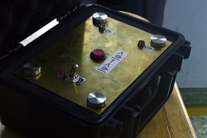
There are three main parts on the device:
- A 555 timer in astable mode that generates a rising edge on a regular basis (the period can be modified with a potentiometer the user can control). This is our clock signal for the sequencer.
- A CD4017BE decade counter that enable up to 10 different "outputs" each time the clock signal rises. This outputs are attached to 10 different potentiometers, so each one can be adjusted separately.
- An Atari Punk Console (made with two more 555 timers). The first variable resistor is actually a direct connection to the 10 outputs from the counter (there's a diode on each one to made it work without "conflicts"); so each time the clock triggers a change, the value of that resistor changes too (or not, it depends on the knobs position!) and the sound generated by the APC becames different.
There's also a knob for the second potentiometer in the APC (but this will be the same for all the different outputs) and a bunch of switches to force a reset in the decade counter - this will allow the sequence to "end" before the 10th output, once the switched one is triggered.
Some of its features (or things I like about the device)
- Up to 10 steps (the max amount of outputs for a single CD4017)
- Reset switch on every step
- Adjustable Clock signal
- Built-in speaker
- Battery-powered (two 9V batteries)
- LEDs everywhere! : D
Things that went wrong / things I need to fix / things interestingly enough to mention / TODO ?
- There's a weird polarized capacitor on the APC section (the one on the first 555 timer) that should be a non-polarized 0.01uF instead of a 0.1uF one - at least according to the "classic APC recipes". While trying to debug some issues with this part I switched to the closest polarized capacitor I had, and this was the only one I could find. It turns out this wasn't the problem (or maybe the original one was broken, but definitely it wasn't the only problem - tl;dr: make sure your potentiometers actually work) but since it worked and it was already soldered in place... well, it seems to do the job pretty well - not an expert, but I think the value difference is, at least, not very important here.
- There's a misterious 220ohms resistor near the speaker. Again, I added it when testing a couple of problems and I just leave it there (it's also in the schematic diagram, but unless you wanna add one of those filters with a couple of resistors this one can be easily ignored).
- The APC second potentiometer works weird with very low values (that's probably not a problem but the fact that the resitor is just too low). Somehow I should avoid going under certain values - for now I have a 1k fixed resistor in series to prevent a 0-ohms-scenario, but obviously it's not enough.
- The first reset switch is useless, since each time the reset is triggered it started again on the first output (so it never "stops"). I noticed that later, but I chose to leave the switch there because I didn't want more "unused holes" in the box :_ D
- Need to improve my abilities for "drilling a case and putting everything inside a box". This time it worked more or less well, but still there's a mess of wires and floating resistors and diodes. Also there are scratches here and there, and the speaker's hole shows some cracks and extra fitting space that I should have avoided when drilling.
- I wanted to add an output jack with an output-selector switch, but I ended up using...

 Alain Mauer
 Keri Szafir