 Andrew Bahls
My initial design concept included 2 different designs. A manually actuated version using some form of push-push mechanism similar to a click pen, and an electromechanically actuated version that could be computer controlled.
I created a few prototypes of the manually actuated version, using a push-push track and wiper design I found on the internet.
The above picture is of my first prototype, which used a wiper and track design. However the wiper wasn't supported in the track, and had a tendency to pop out. My FDM printer was also unable to resolve the fine details of this design, keep in mind that the center square was only 1". This was also the only iteration where I had the wall units in line with the grid. My later iterations rotated the design 45 degrees, so that the mechanics fit on equal sides of the wall, with 4 wall units making up a grid square.
These next 2 pictures are from my second iteration of the manually actuated design. This time I used a sliding wiper, that was supported on either side by a mirrored track. I also used a single spring at the bottom, rather than the dual springs on tracks from the first version. This version was somewhat successful (I unfortunately don't have any clear photos of the printed version). Once I found a spring tension that worked, I was able to push the wall down, and it locked into it's lower position. However it couldn't unlock from that position and return to it's extended position. I retired this design when it was clear that my FDM printer would be unable to properly resolve the precision to refine this design.
At this point, I had moved on to work on other projects, so we'll fast forward to a few months ago. Hackaday featured a few articles on flip-dot displays, and I considered using a similar method to actuate my electromechanical version, which I had yet to prototype in CAD. I had also matured considerably with Fusion360 over the past year, so tackling a more complex design was more feasible.

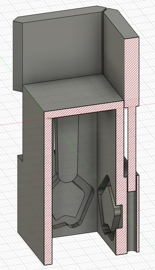
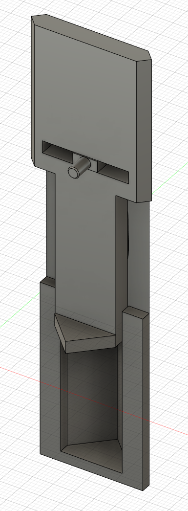
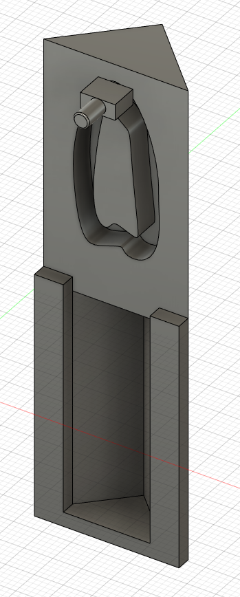
This design utlizes the M3 brass threaded inserts I've fallen in love with using in 3d printing, as well as some 3mmx7mm bearings I found on Amazon. I'm very pleased that I was able to get about 20mm of travel with this cam mechanism. However, once I had 3d printed the design and put it together (learning that I hadn't considered ease of assembly in the design), it was clear that an electromagnet pushing a magnet on the cam shaft would probably not overcome friction enough to rotate the shaft 180 degrees (though I haven't actually tested it yet).
It's at this point that I'm posting the project on Hackaday.io. I'm pleased with the cam actuation giving me a stroke length of ~20mm, and it fits within a 28mm grid with 1/4" thick grid walls. However, I need to consider some alternative actuators. Servos or geared motors would be easy to adapt to this design, but I'd have to wire up thousands of them for even a small table size. I also don't need the analog control, the walls only need to be fully extended or fully retracted.
Discussions
Become a Hackaday.io Member
Create an account to leave a comment. Already have an account? Log In.