 zaphod
Here's the device's circuit in all its ugliness:
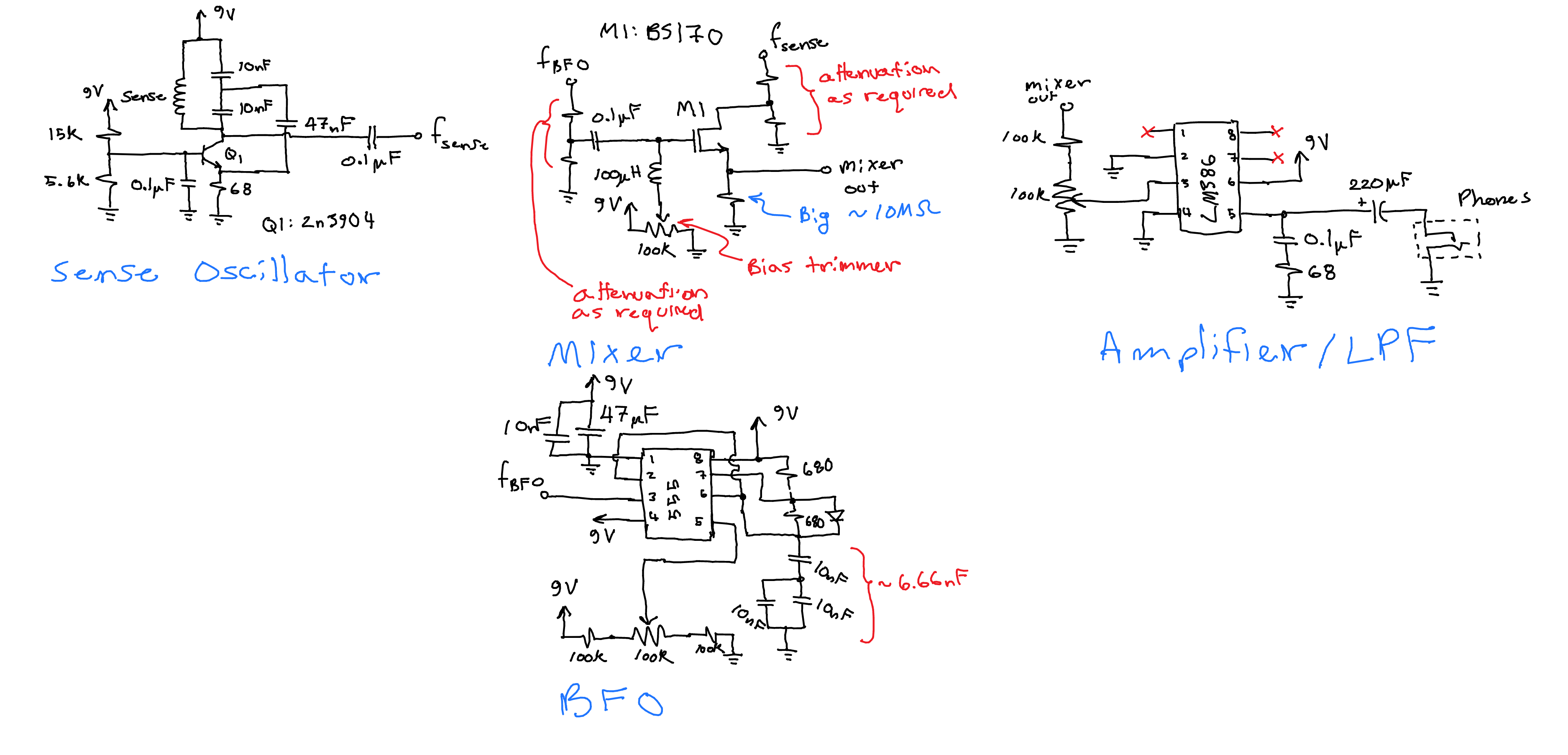
The Sense Oscillator
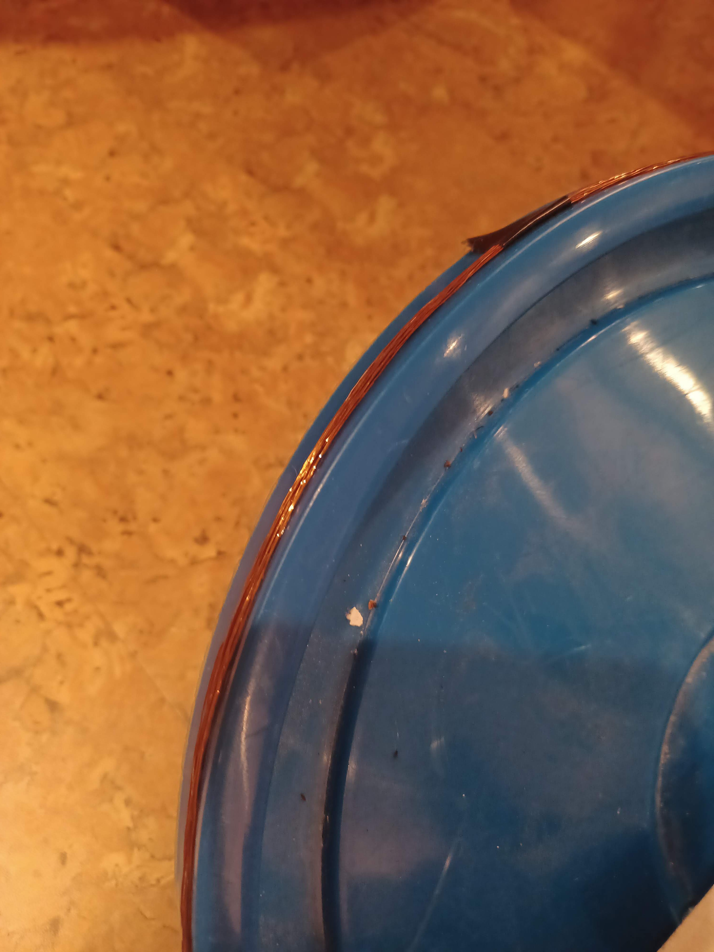
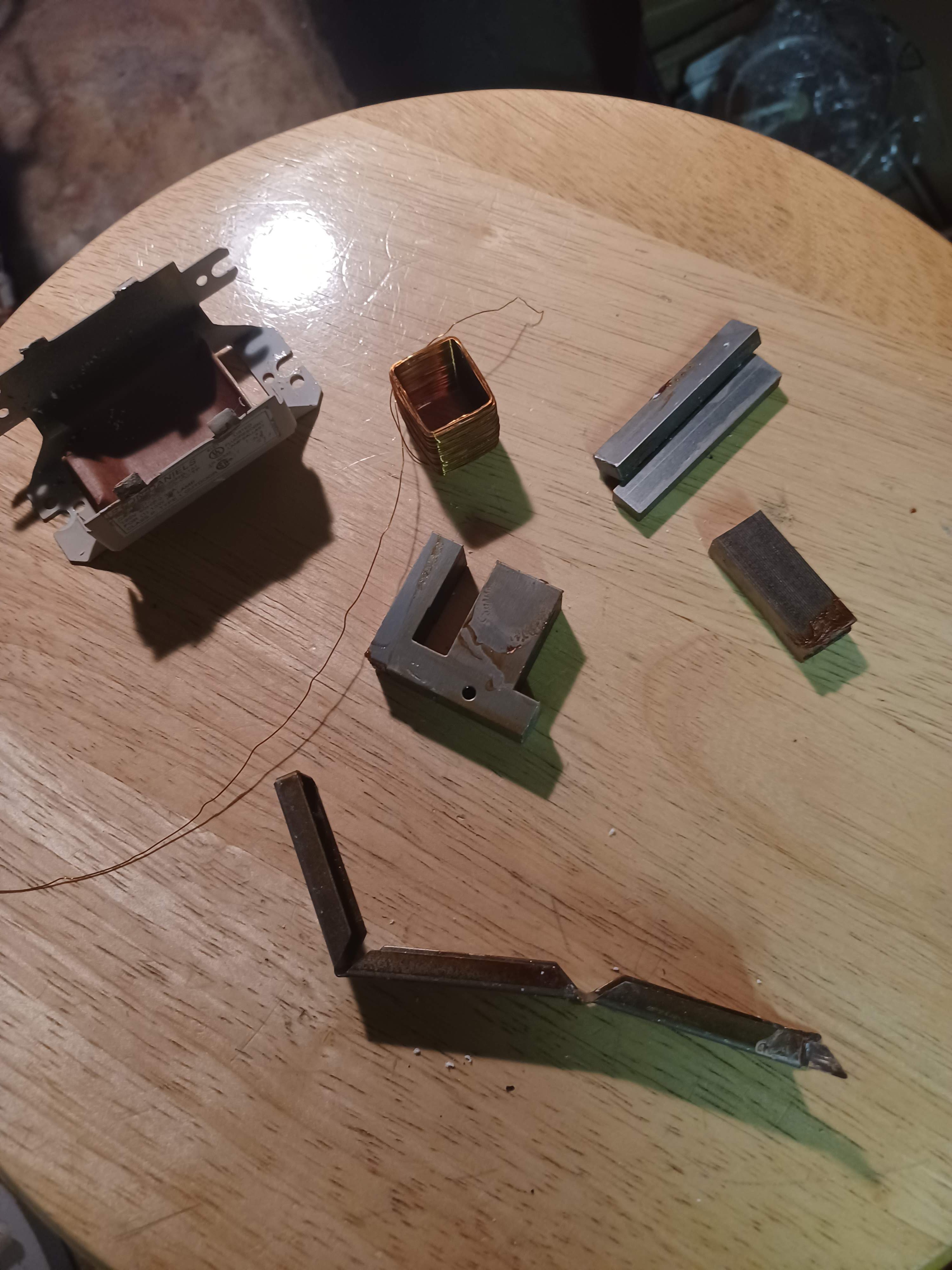
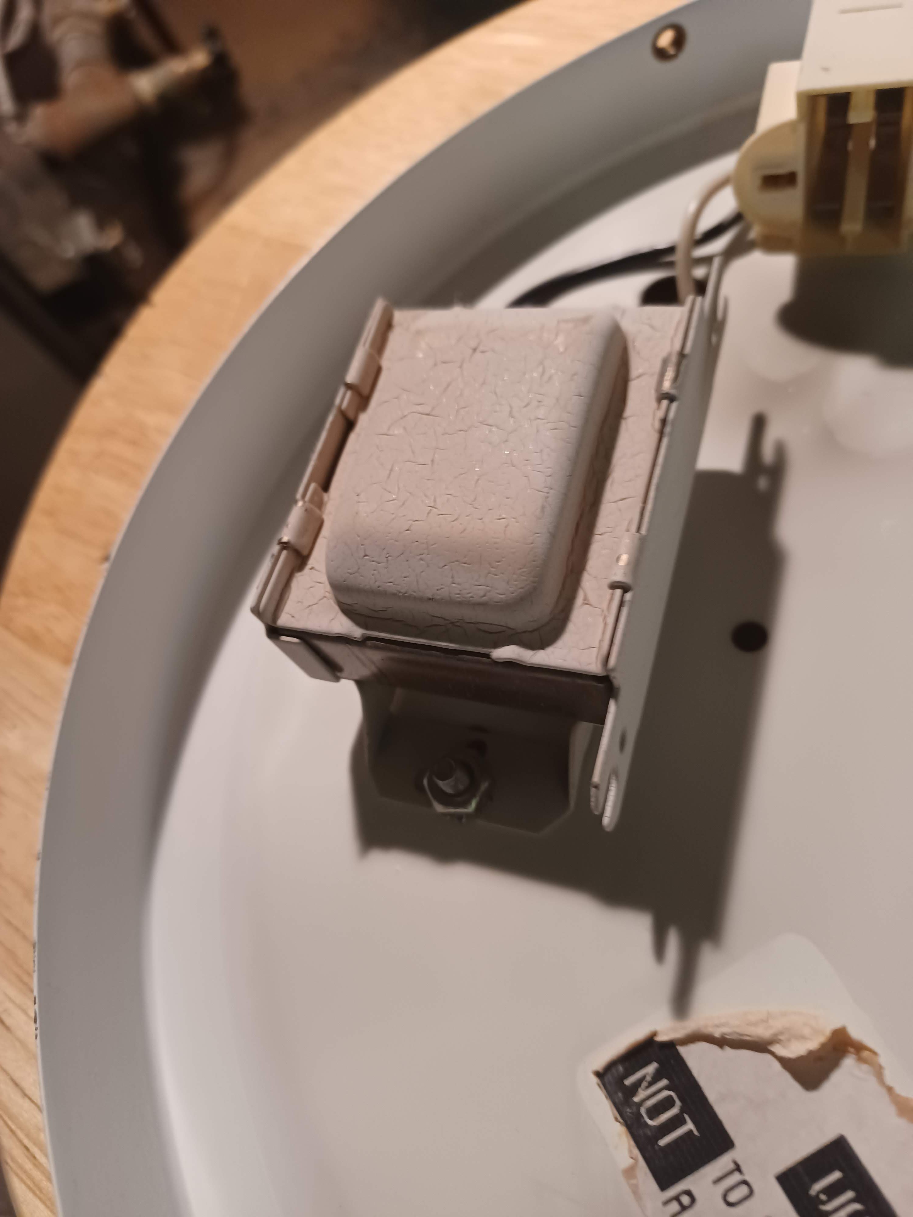
The sense oscillator is a garden variety Colpitt's oscillator, based around a 2n3904. With the component values above, and the coil I wound it oscillates at a frequency of approximately 136 kHz. The coil in the tank circuit is the device's primary sensor, and was constructed by winding magnet wire around the edge of a drywall bucket lid. The magnet wire was salvaged from an old fluorescent lamp ballast, which are apparently just giant inductors.
To make the coil I pried apart the lamp ballast, hack sawed the core apart, dug out the magnet wire, and then wound ~27 turns around the drywall bucket lid. No idea what gauge the wire is, but the finished coil has a resistance of 8 ohms, so its pretty low Q. the diameter of the coil/bucket lid is approximately 307mm.
some picture of the lamp ballast and coil:
The BFO
The BFO is a simple 555 timer astable circuit. It includes a diode across pins 7 and 6 to equalize the charge and discharge cycles so that the output is a square(ish)wave. I also have a potentiometer connected to pin 5, which provides a bias voltage to the threshold comparator. This potentiometer is the device's tune knob. Basically by adjusting the BFO frequency one can set the output tone that is heard in the earphones. With the values in the circuit above I was able to get the BFO to go from ~119 to 150 kHz, which allows the operator to get the BFO frequency on either side of the sense oscillator frequency. This means that the operator can tune the device such that metal is detected as either a lowering pitch or an increasing pitch, depending on if the BFO freq is above or below the sense freq.
Note the decoupling capacitors on the 555. These need to be placed as close to the 555 as possible, and are responsible for stopping the BFO from coupling to the sense oscillator. Without these capacitors I found that the BFO would overwhelm the sense oscillator and the sens oscillator would just end up oscillating at whatever frequency the BFO was running at, which completely stops the circuit from working.
The Mixer
The mixer is easily the worst part of the design. Rather than going with a proper design I just kludged stuff together on my breadboard until I got the output I wanted on the scope screen. Don't build this circuit, or at least do some spice sims first to try and get some better component values.
The basic idea is that the BFO (which is a square wave) gates the sense oscillator (which is a sinewave), and this produces a harmonic at |f_BFO - f_sense|. The attenuation resistors were hacked in last minute to try and stop the audio amplifier from producing an earshatteringly loud noise, and I definitely should have just adjusted the amp gain rather than attenuate my input signal but I did this in a hurry.
The trim pot is there because I didn't want to work out bias network values, and instead I just aligned the circuit by checking the mixer product on my scope and spinning the trimmer until the signal reached a maximum.
The Amplifier and LPF
The amp is literally the reference circuit for the LM386, but with some component value substitutions based on what I had on hand. Instead of building a proper LPF I just pretended that the LM386/headphones/my ears, would filter out the higher order harmonics enough. This 'works' but the output signal is still pretty awful to listen too. Again the name of the game here is fast and bad, and this is that.
Discussions
Become a Hackaday.io Member
Create an account to leave a comment. Already have an account? Log In.