Ratti3
Features and design
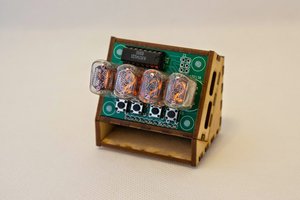
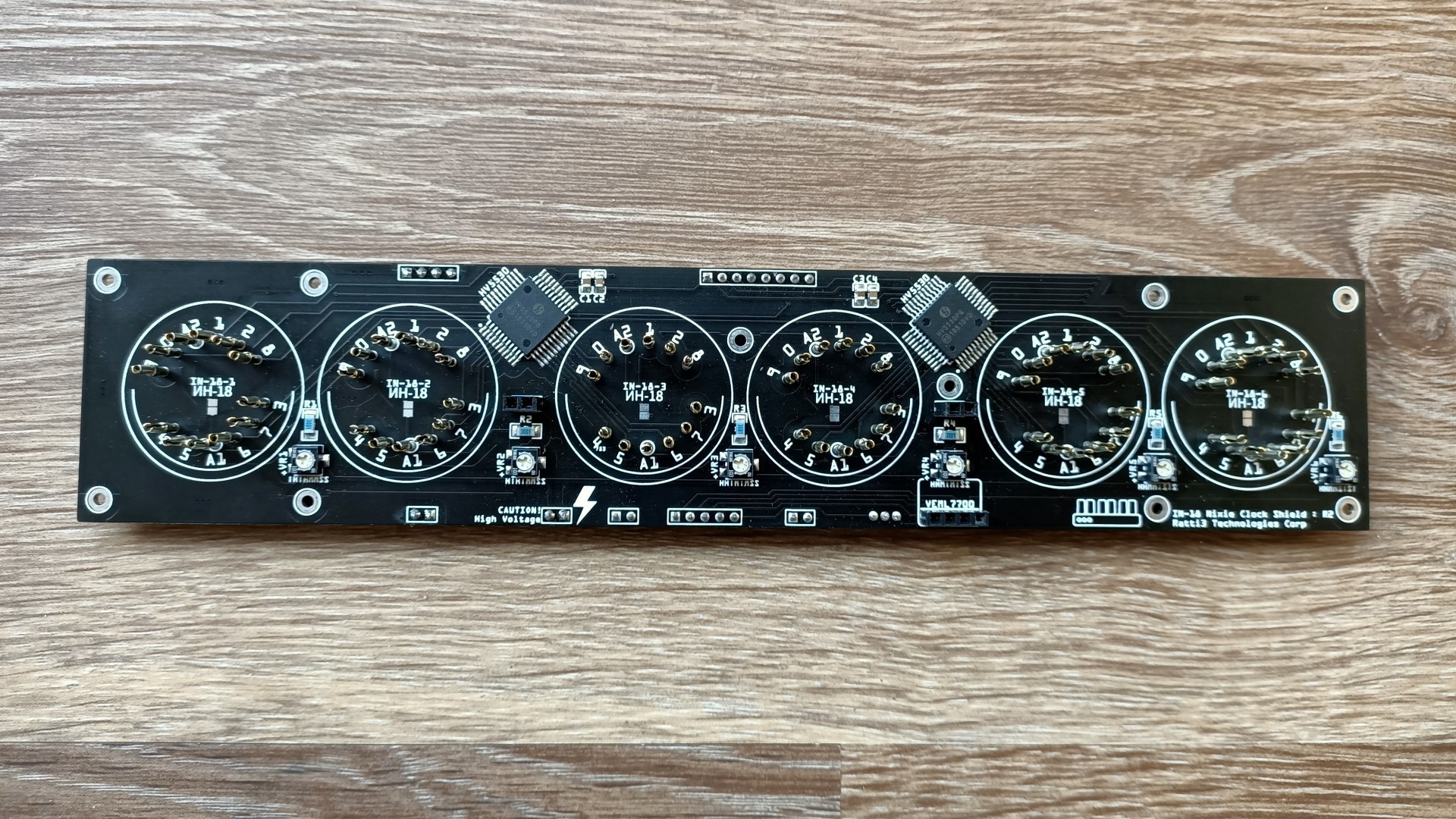
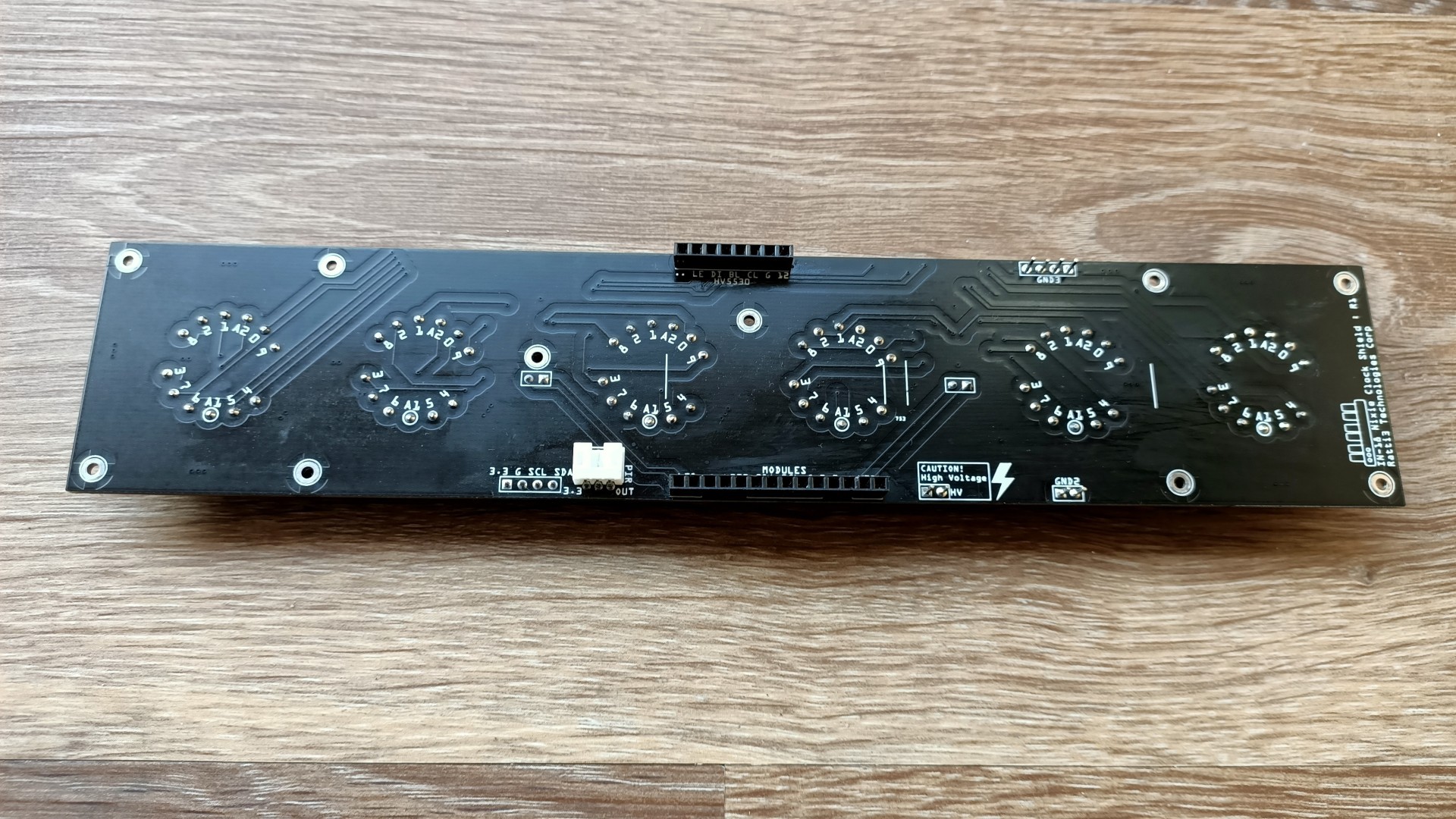
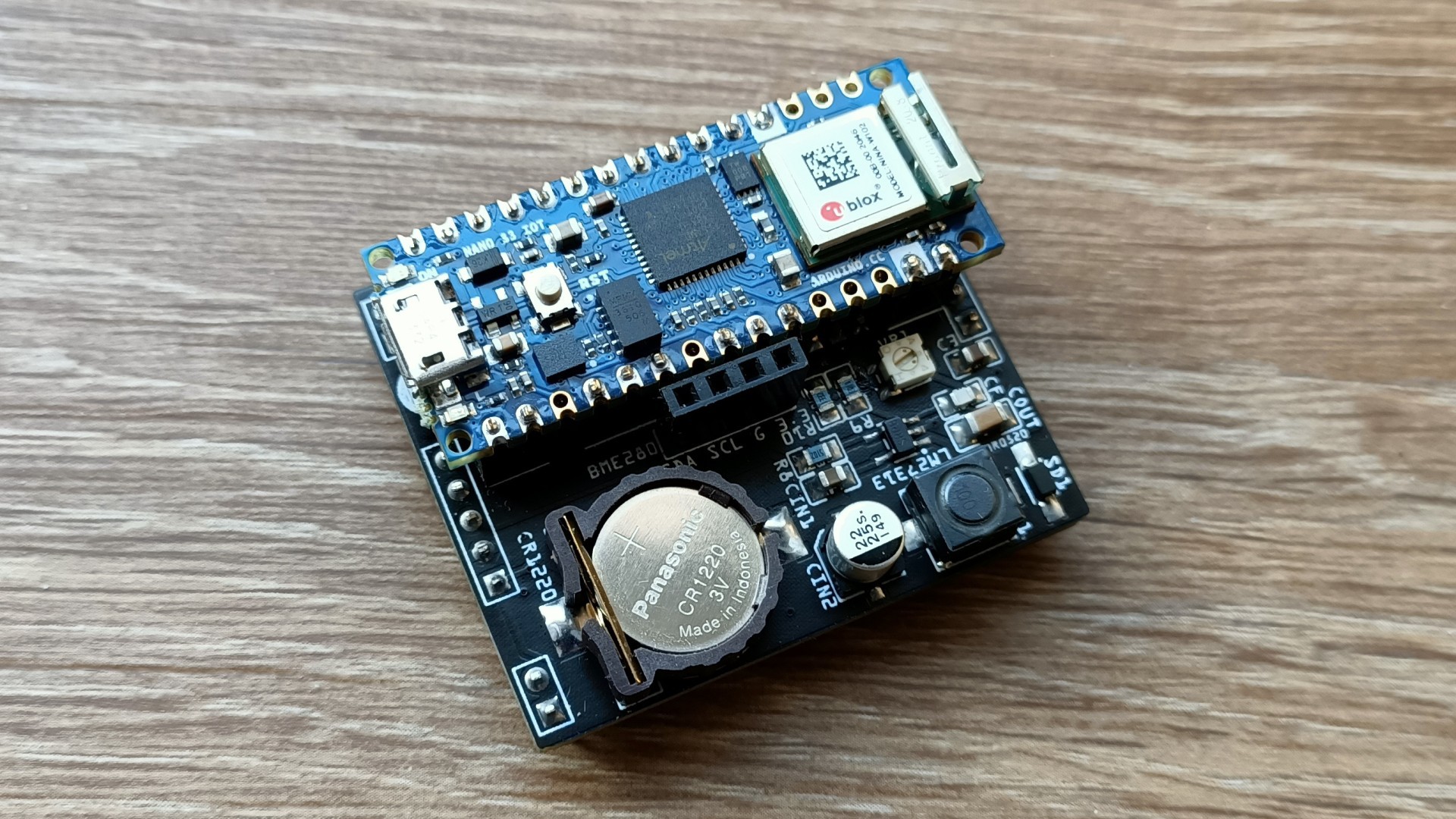
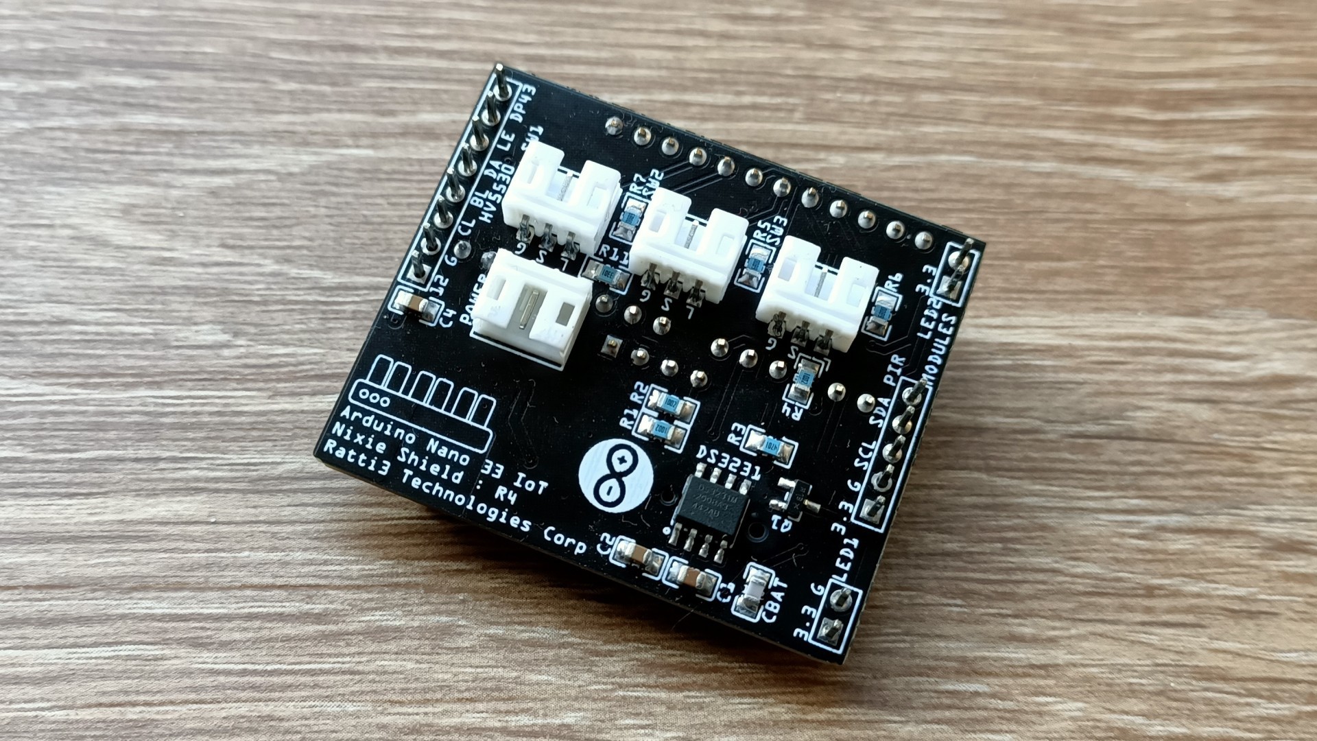
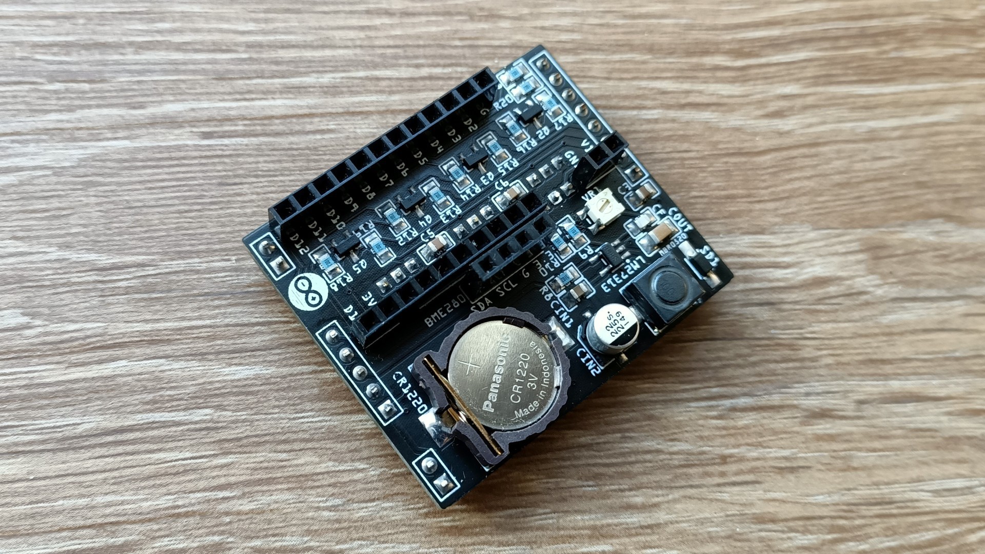
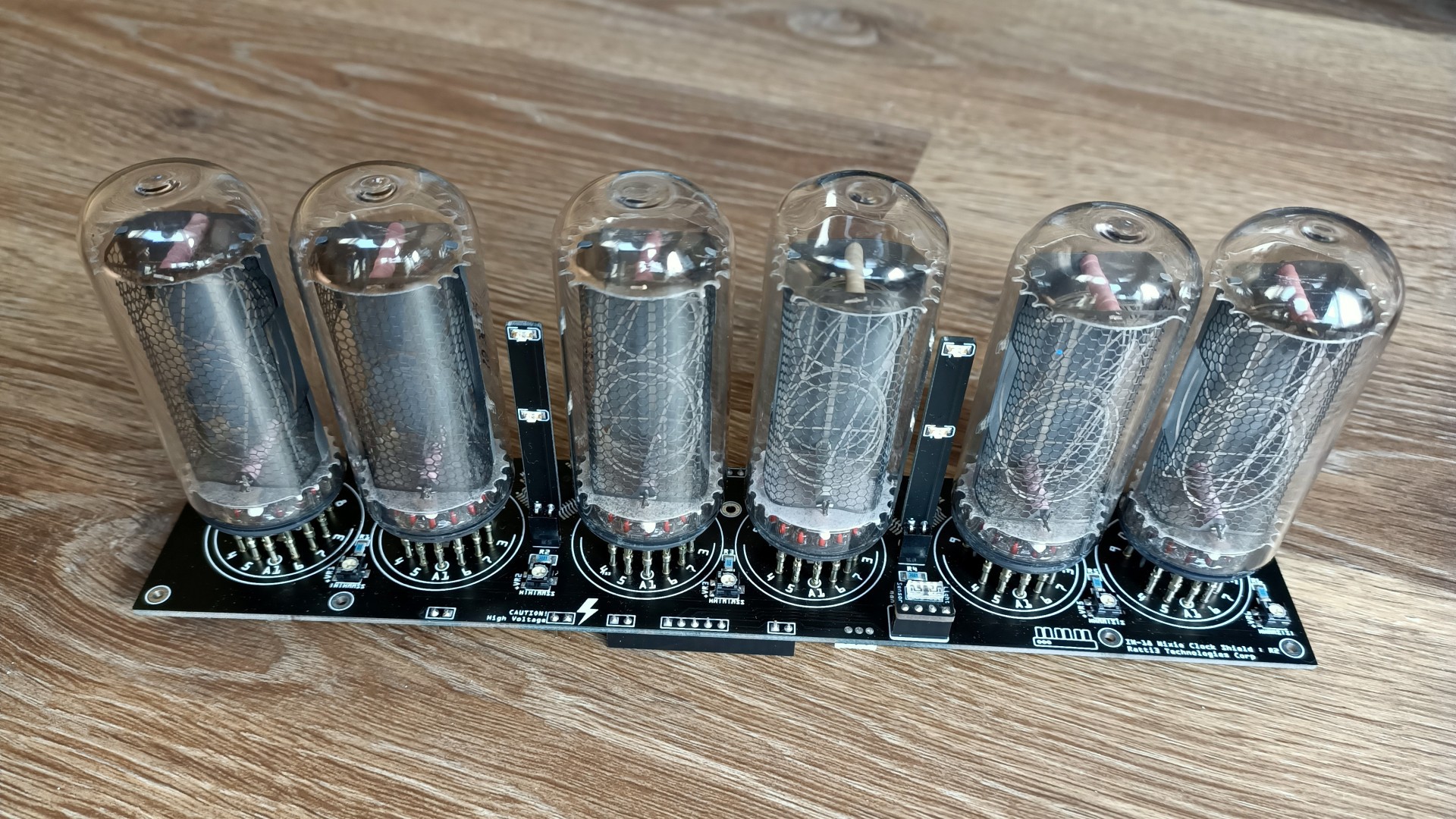
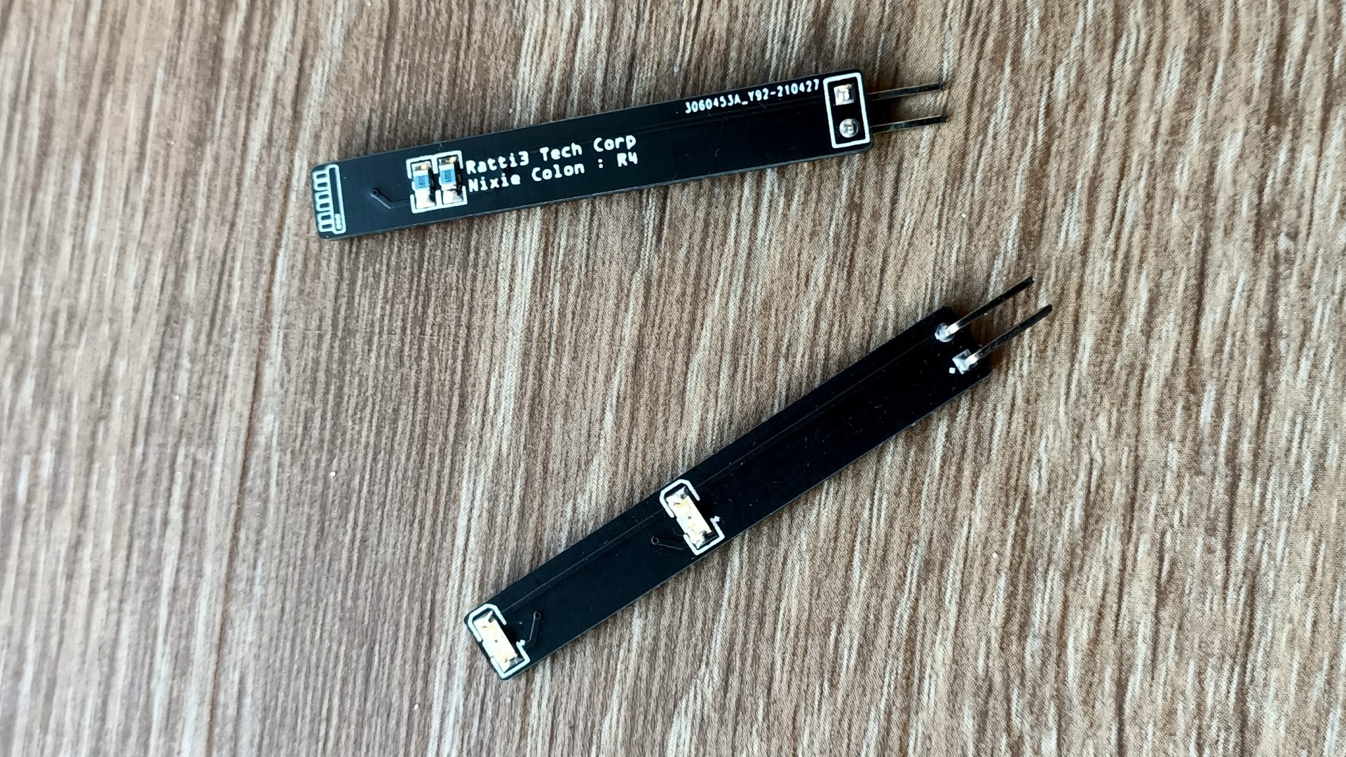
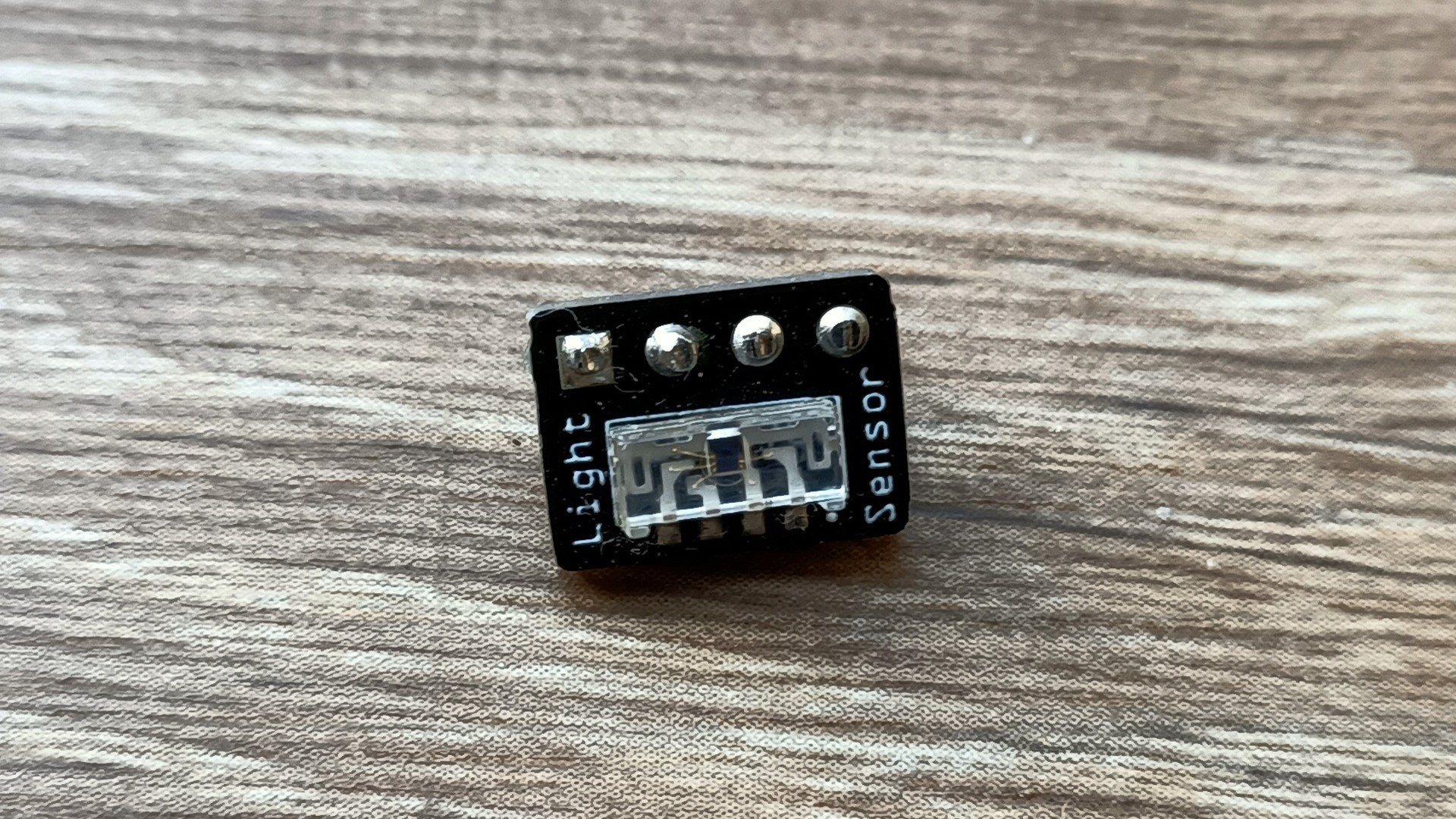
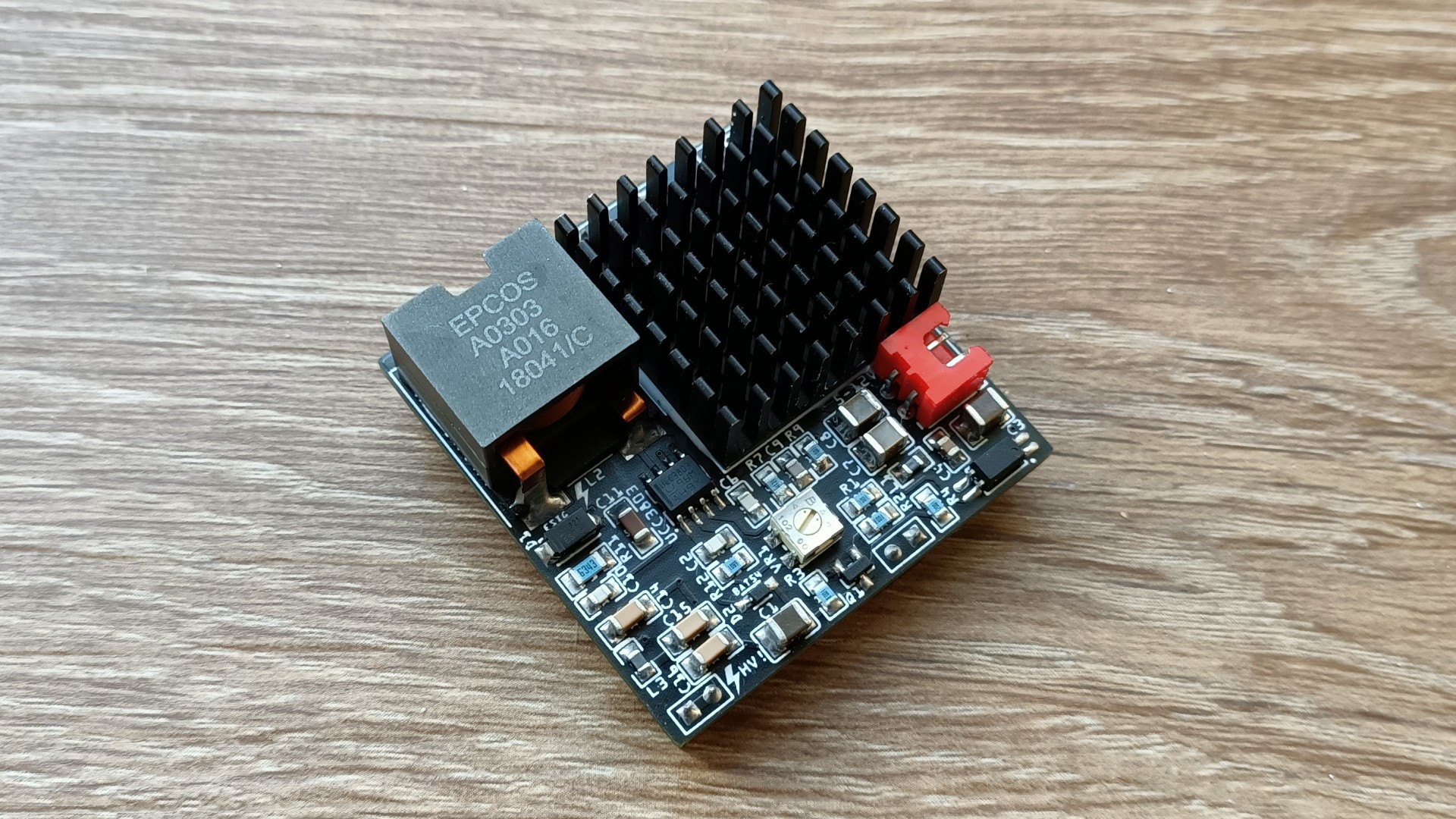
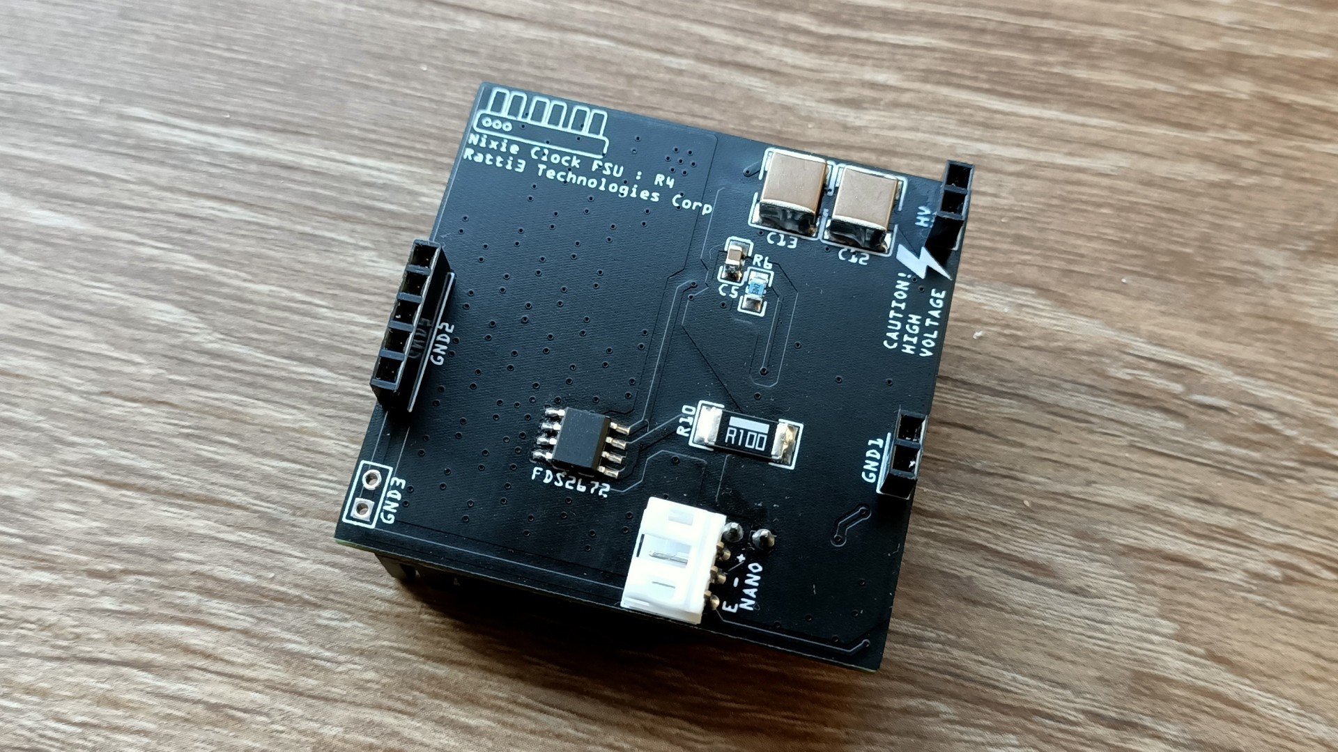
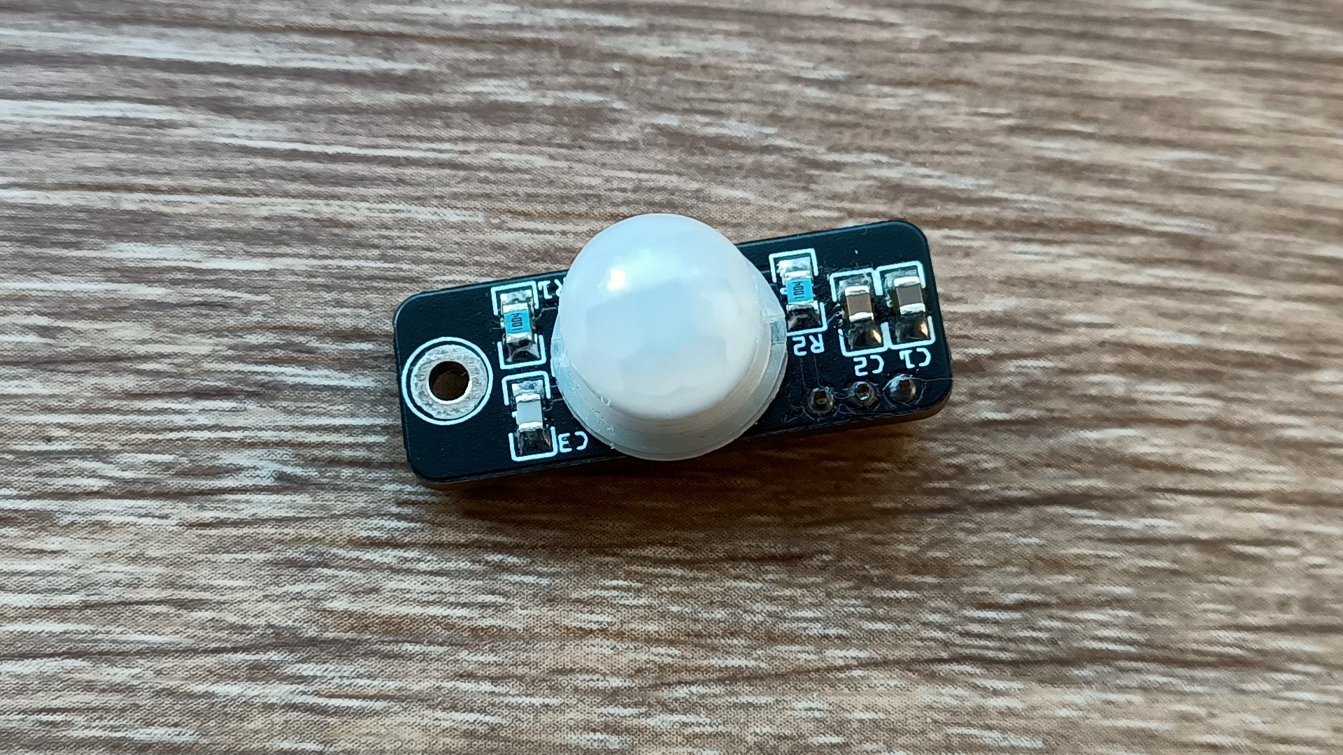
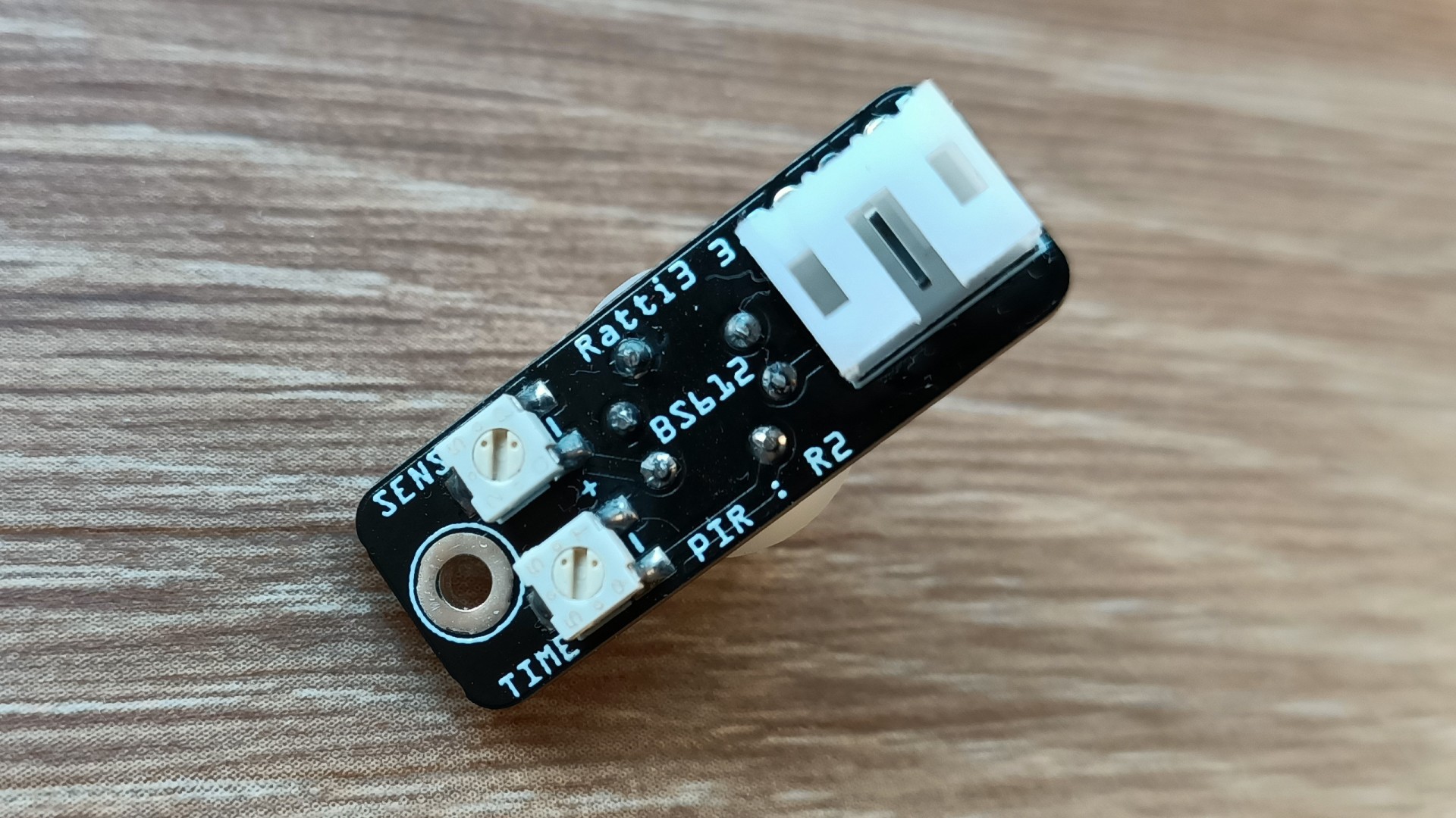
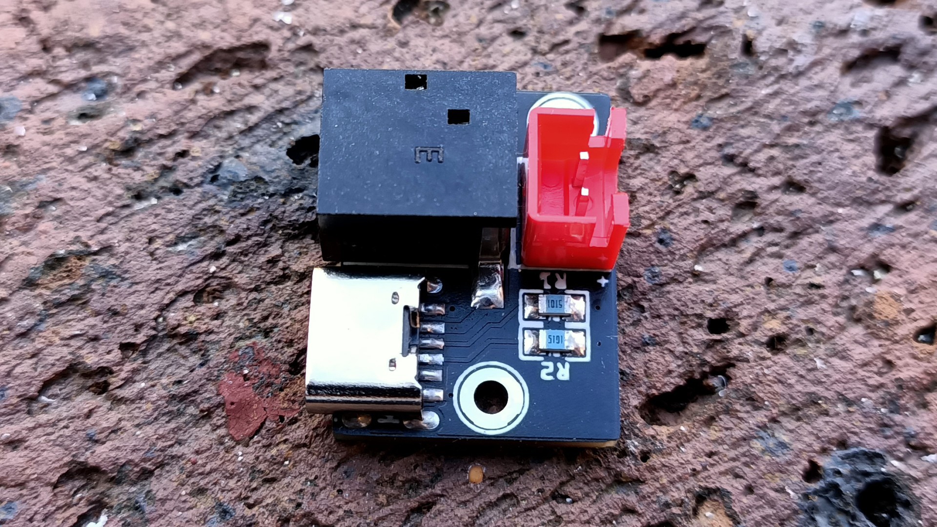
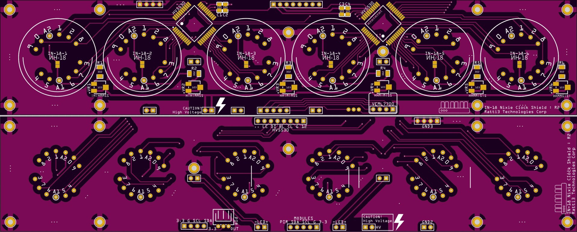
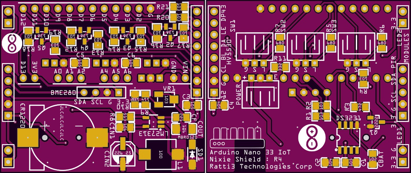
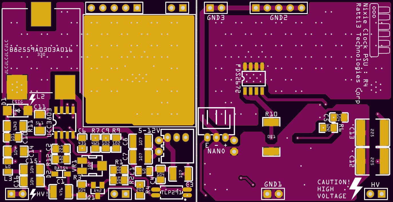
The clock has been made to be as modular as possible, the PCBs consist of a main Nixie board, Arduino Nano board with DS3231 and 12V boost convertor, HV PSU based on the TI UCC3803D that runs on 5V or 12V, a VEML7700 light sensor board, a BS612 PIR sensor board, a BME280 environmental sensor board and a power input board.
The modular design means modules can be interchanged with other future variations on this clock. I've already made a IN-12 version of clock.
The Nixies are driven using the Microchip HV5530 IC, this chip is capable of controlling each digit individually without having to multiplex.
It's designed to run from a 5V USB power supply or from a 12V wall plug.
When powering on the clock for the first time after a code upload, the Arduino will broadcast an AP SSID called NixieClock, the password is nixieclock and the default IP is 192.168.4.1.
Once you connect to this SSID, you can configure the clock by navigating to http://192.168.4.1, and connect to your own WiFi. The web interface additionally allows you to change various settings like brightness, NTP options, motion sensor, light sensor and date/time.
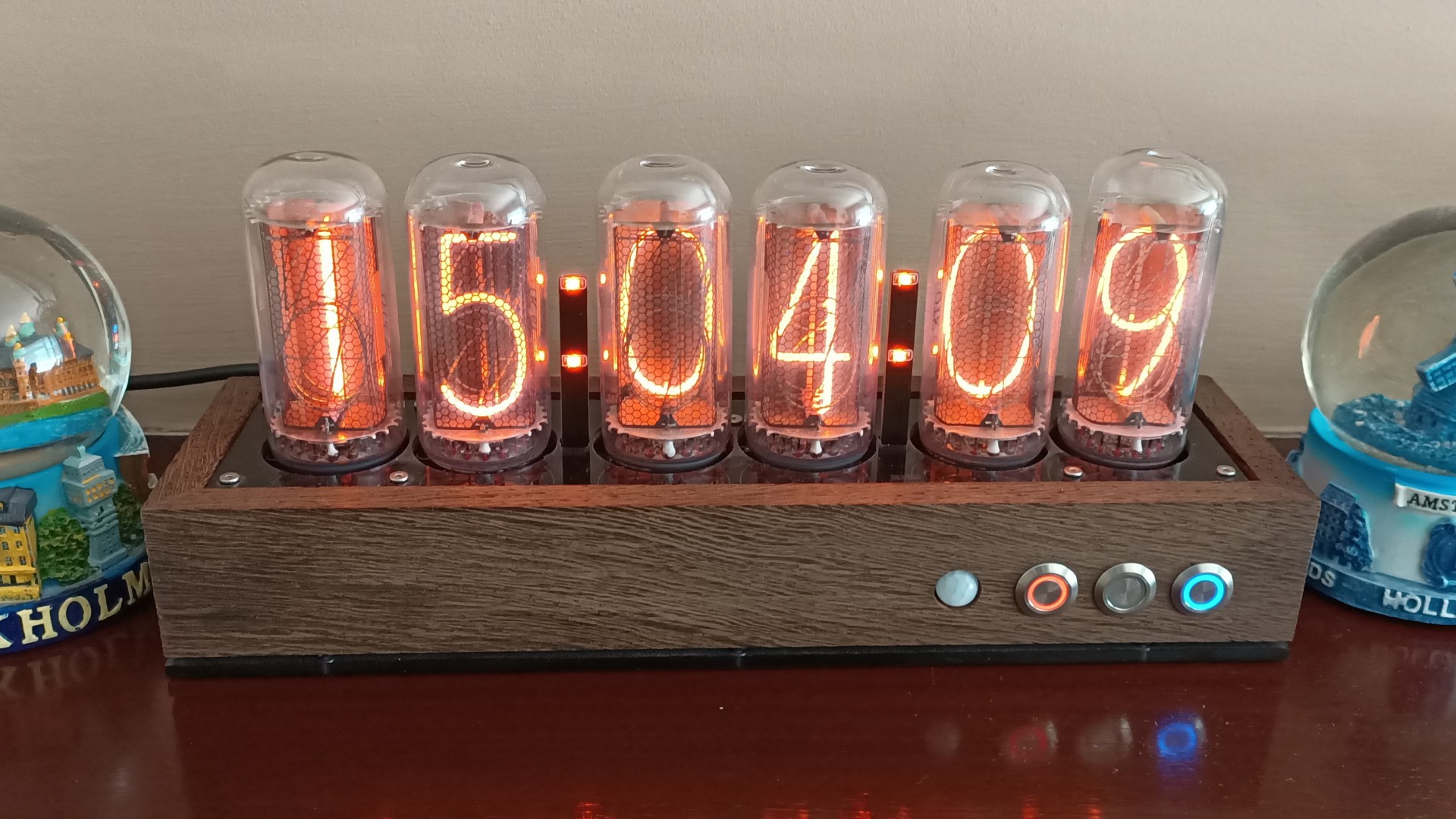
The clock is designed to turn the Nixies off when no one is in the room, this is achieved via the BS612 PIR sensor. A VEML7700 light sensor works along with the on/off schedule to determine if the clock needs to be turned off when it's night/bed time.
Every minute all the digits on the Nixies are cycled through using various patterns, this is to reduce cathode poisoning.
As the HV PSU is adjustable, the main Nixie board has trimmer potentiometers for adjusting the anode current.
The three buttons on the front are to display the date, environmental readings, IP address and setting the date/time manually.
YouTube Video
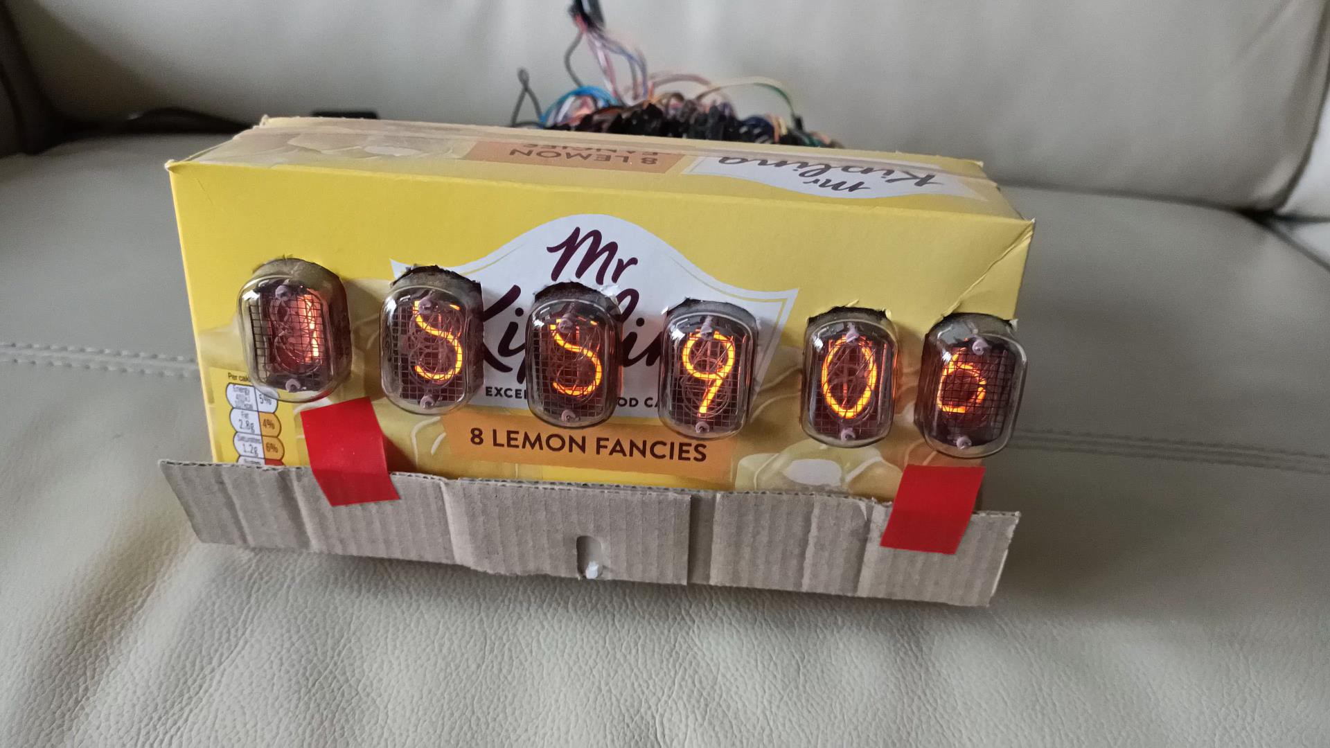
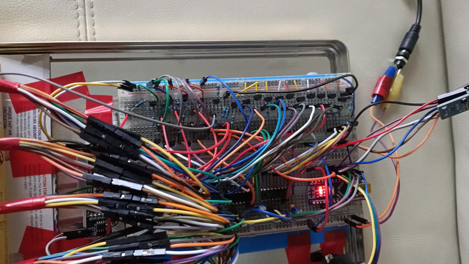
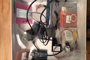
Original Prototype
I had to devour a box of Mr Kipling cakes quickly so I could build the prototype:
 |  |


 Pierre Cauchois
 mdresf