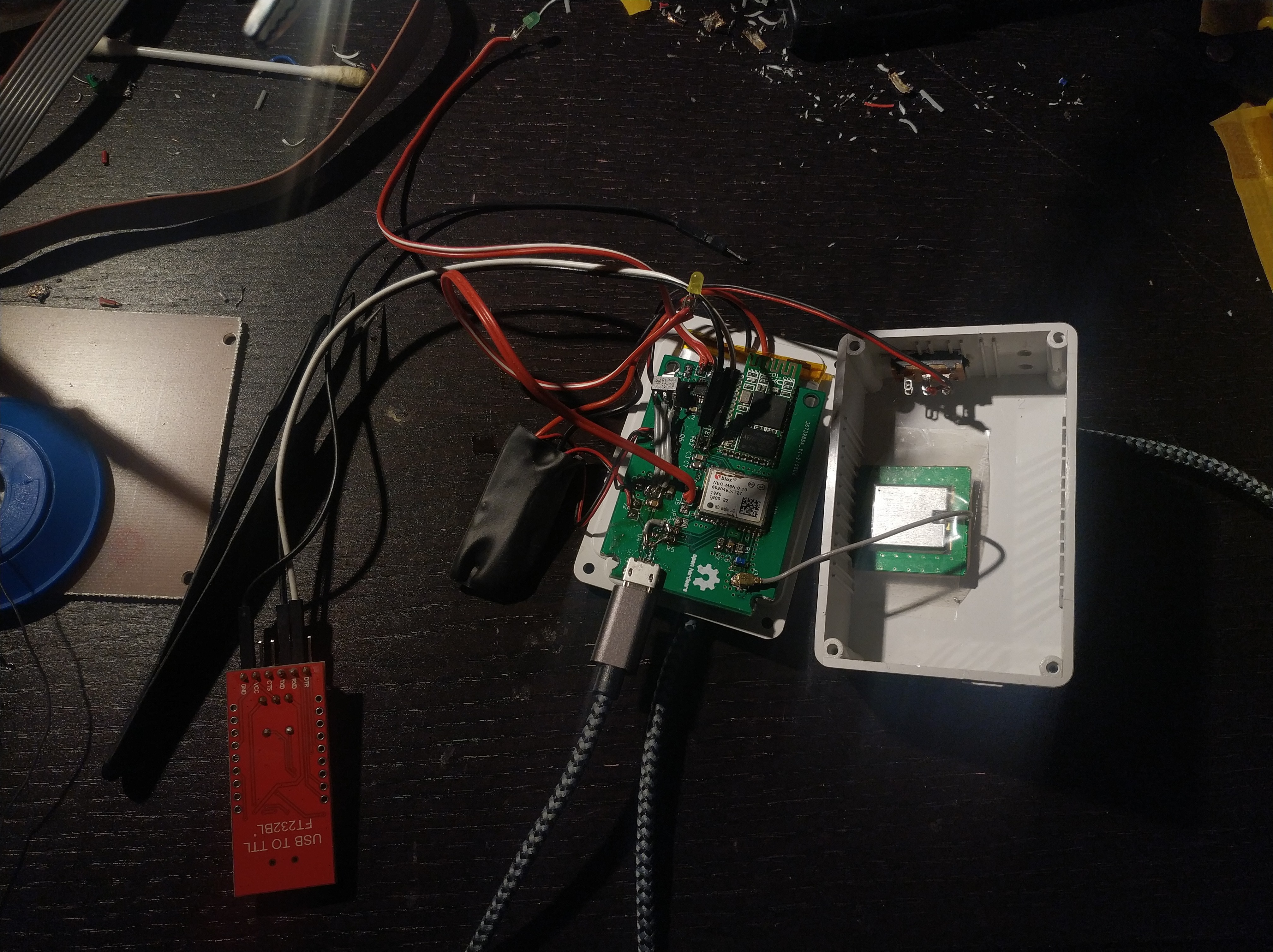
This is the second version of my GNSS module which sends NMEA strings via Bluetooth to a mobile device.
The main changes are:
- No antenna reflection backplate, instead of 7x7 cm
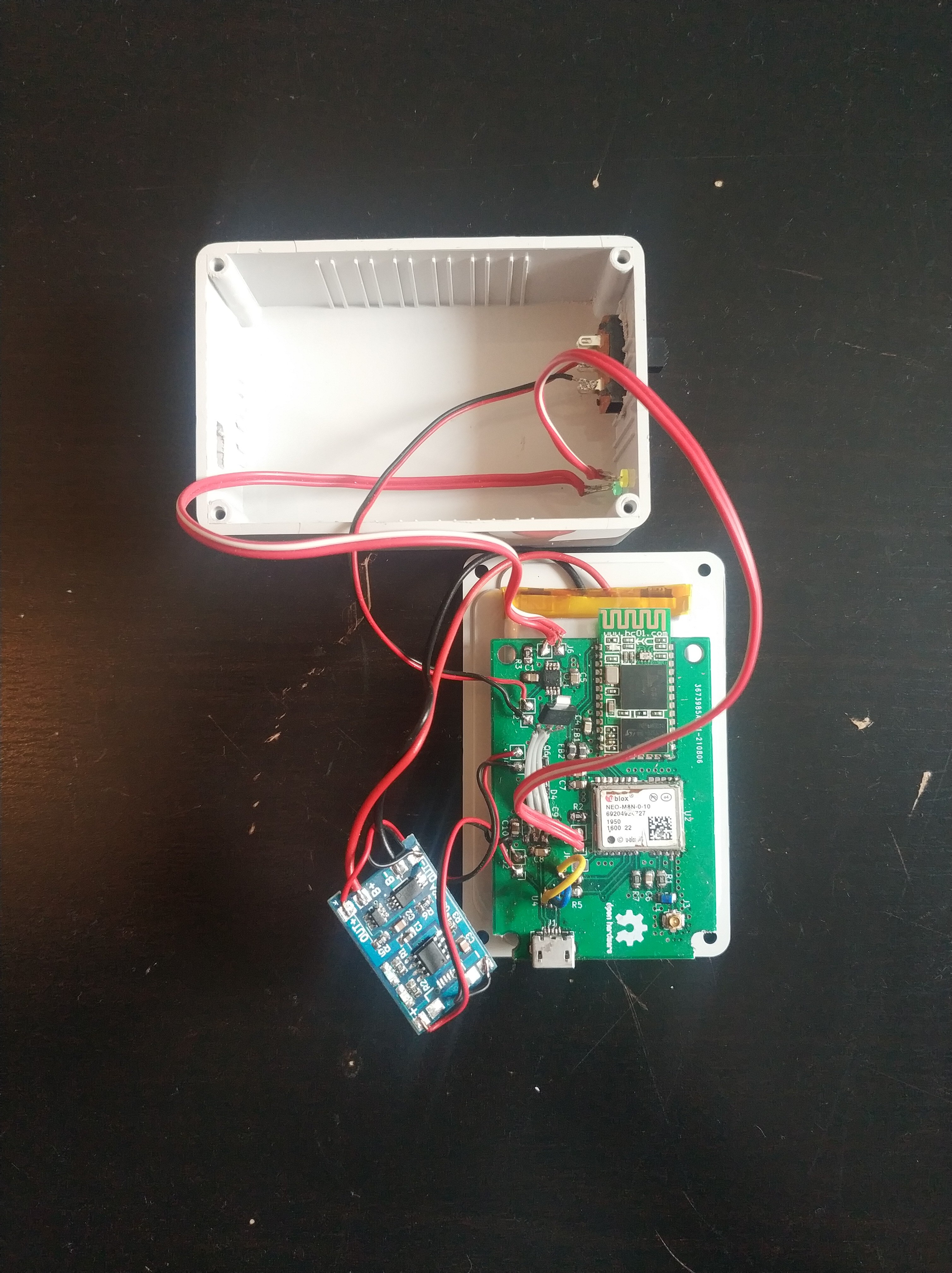
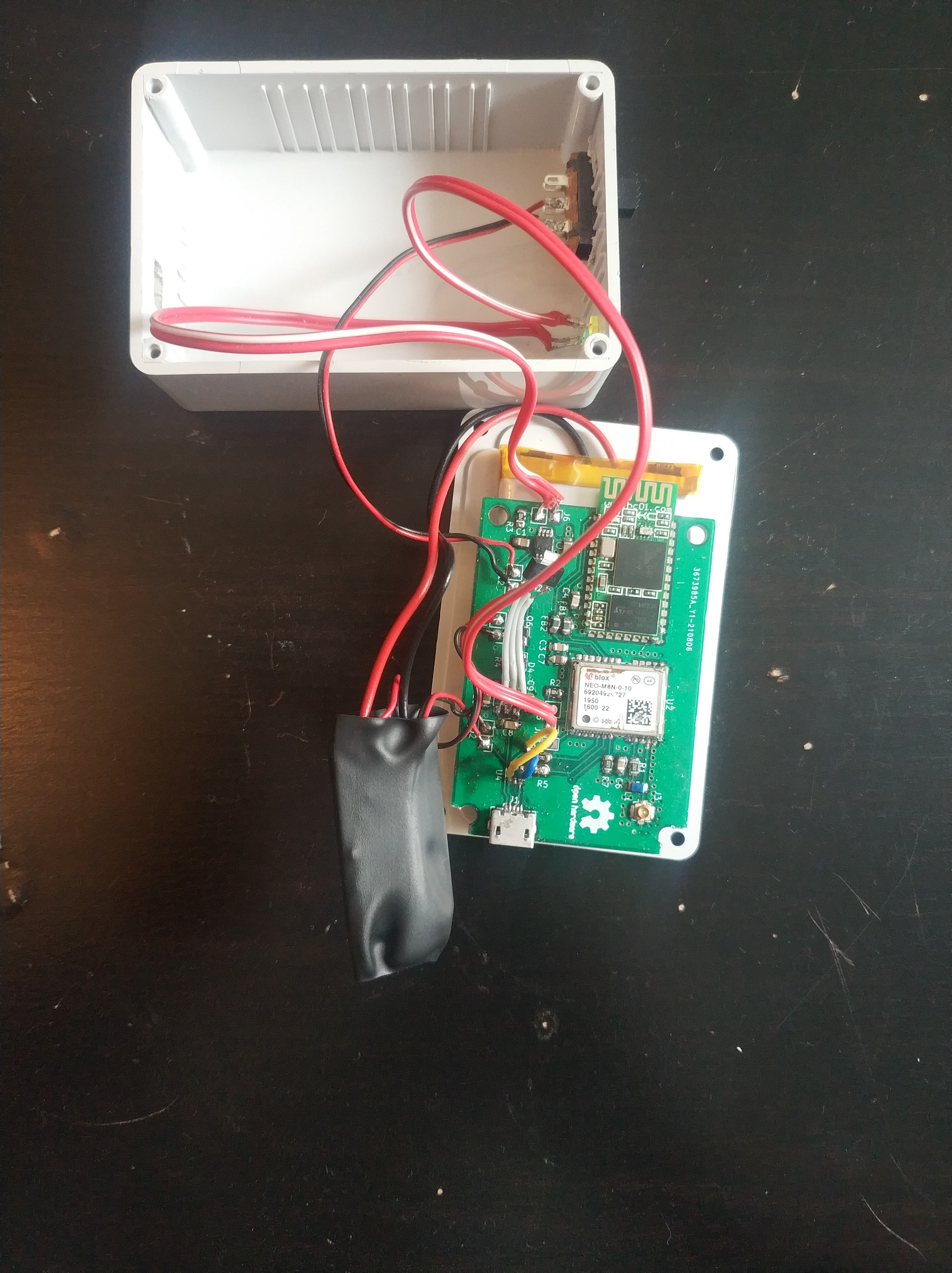
- New GNSS patch antenna with > 20 dB gain low noise amplifier
- Smaller battery (18650 is changed to a Lipo 1100 mAh), should still be enough for 12h+ runtime.
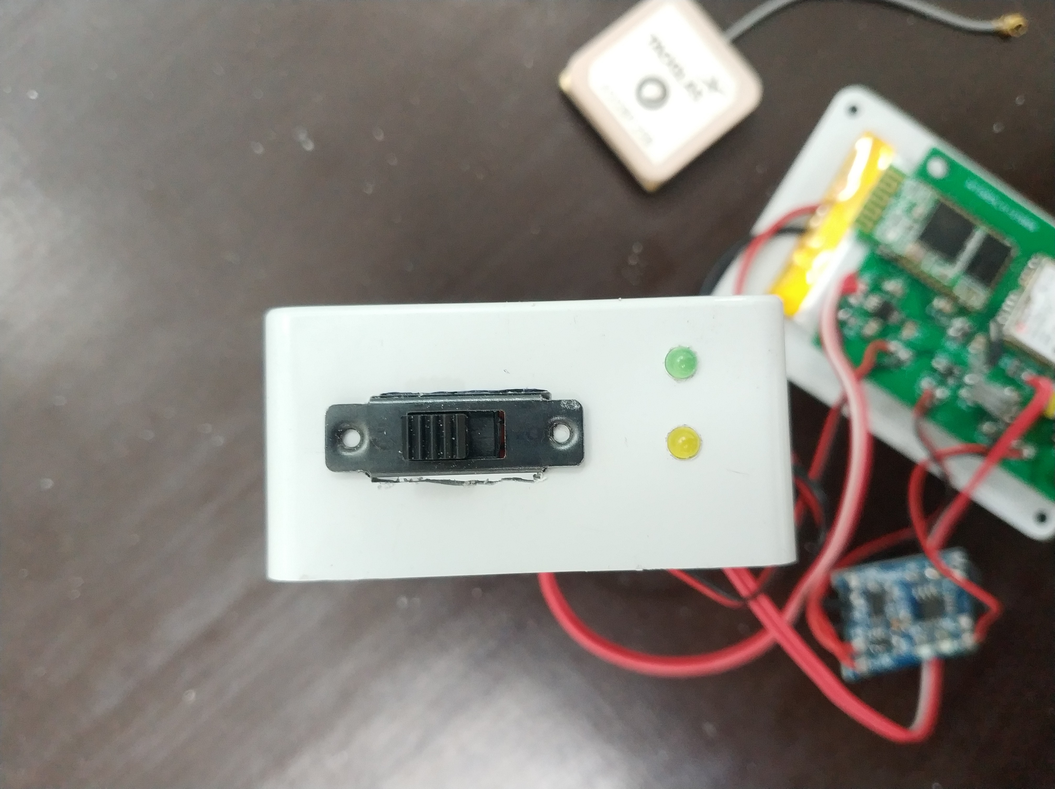
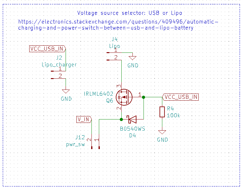
- Charging via USB
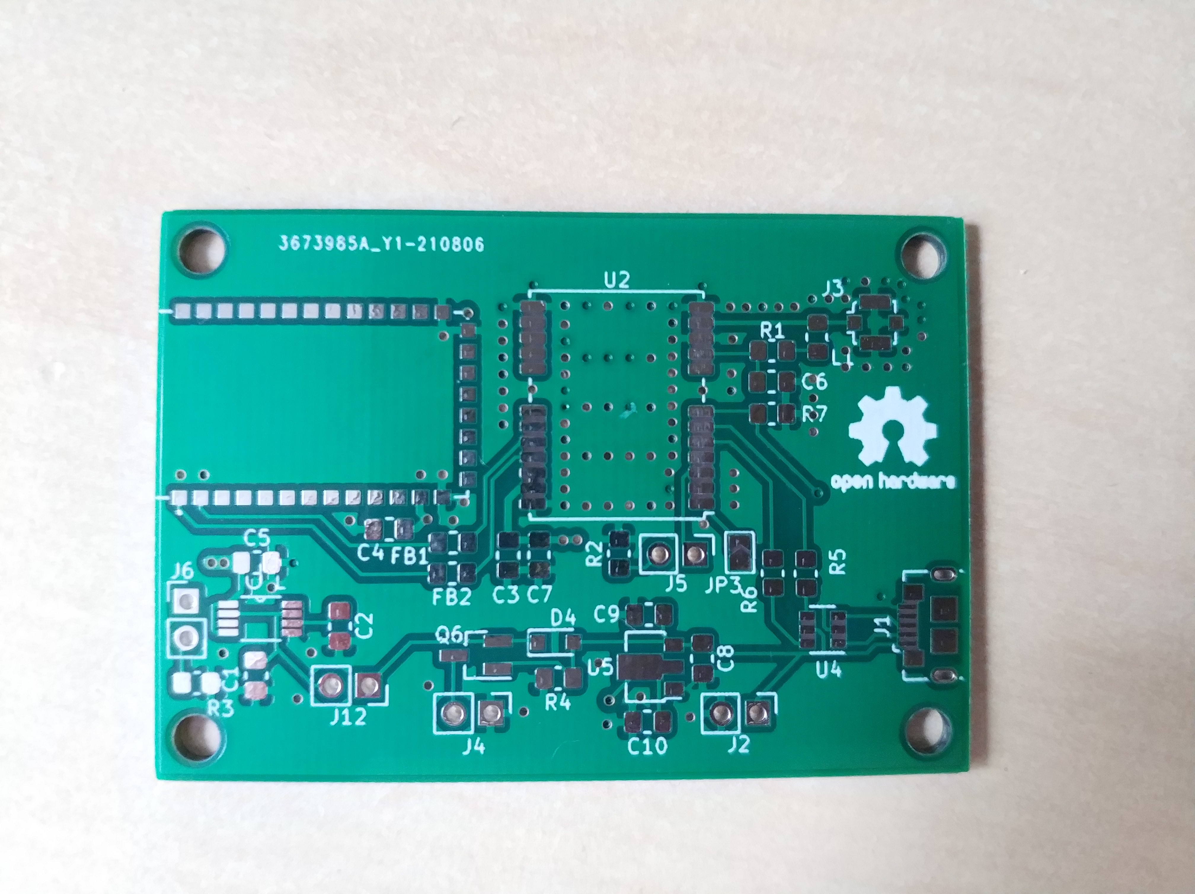
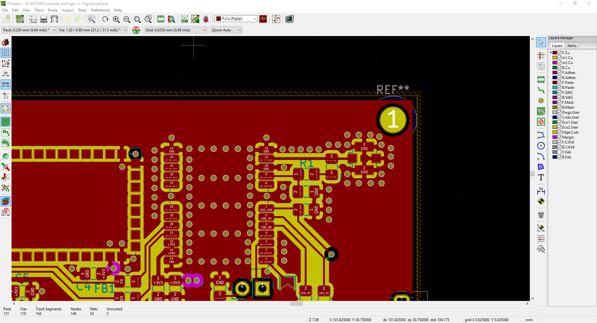
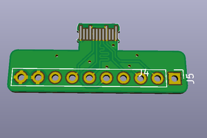
- Better PCB layout regarding the HF-section (tracks should be the correct impedance now)
- I will try to use NTRIP correction data with a smart phone app
The key featured remain the same:
- GPS, Glonass, Galileo, Baidou support
- 2.5 m accuracy according to datasheet
- Connects old Android devices to a position service
- Low energy consumption
- USB-port for u-center programming and as USB-GPS device
- GPS, Glonass and Galileo configured
 Gee Bartlett
 Lithium ION
 Solderking
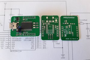
 hesam.moshiri