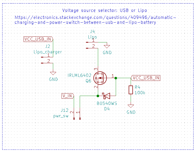
I designed the PCB in KiCAD with version 1.1 in mind. The main changes here are the power selection circuit. I copied the circuit from a electronics.stackexchange.com post which basically describes a part from a Arduino feather 328p. When USB power is not connected, the LiPo will be used. When the board is powered via USB it closes Q6 and the battery is disconnected.
Further changes are regarding the proper impedance of the trace to the antenna connector. In the previous version I neglected this completely. The trace was a normal track (0.25 mm) with bends, the impedance (50 Ohms) was properly way off.
Using the KiCAD calculator and plugging in the values (h=1.6 mm PCB, f=1.575 GHz) of the track in version 1.1 gives a theoretical optimal track with of 2.9 mm. This is way to wide to fit on the connector. Using the real values of my PCB of h =1.6 mm and 0.25 mm track resulted in an impedance of about 130 Ohm (oh boy...). In this optimized version I took special care to design the HF-section of the board as good as I could (again, I am not an electronic engineer). So I changed the design from 2 to 4 layers with a layer height of 0.2 mm to GND. Entering this in the calculator resulted in a track with of 0.349 mm for 50 Ohms. Furthermore I kept the track straight and used way more vias to isolate the antenna track and connector from any noise. The capacitor in the antenna section was changed from 10 nF (reference design in u-blox manual) to 1 nF according to a friend (electronic engineer) due to the Series Resonant Frequency (?). I hope these changes improve the already very good reception of the module.
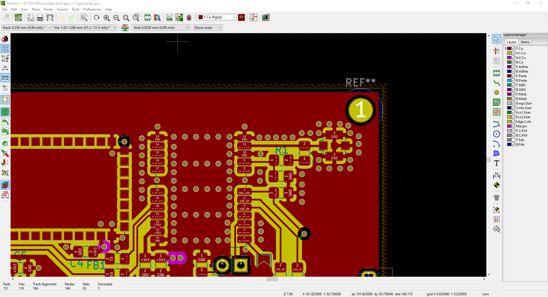
The 4-layer design allowed me to use a Vcc layer for power. An added 10 µF capacitor near the u-blox module should buffer the demand from the chip while searching for satellites. Further smaller changes are the pin headers for the LEDs, LiPO and Lipo-charger as well as way way more vias under the M8N chip.
I am using the cheap TP4056 Lipo-charger on an external PCB for charging the 1100 mAh Lipo.
Due to the 4-layers (and the number of vias^^) I send the PCB to a manufacturer in China, the PCBs should arrive with in the next week.
Discussions
Become a Hackaday.io Member
Create an account to leave a comment. Already have an account? Log In.