 SAYANTAN PAL
Last time I made a reflow soldering hotplate from a regular clothing iron. And it works pretty great. The only issue is it uses mains AC voltage which I don't feel super comfortable to work with so I tried low voltage DC approach.
The Idea :
The idea is simple, when you apply power to both ends of a conductor, it generates heat. So if we make a PCB that has a very lengthy trace and apply voltage to it’s end terminals it should generate enough heat to reflow a PCB. Key things to note here is that different solder paste has different melting point. and since my last experiment 200 to 220 degree celsius should be sufficient for the solder paste that I use.
Choosing PCB type :
So regular FR4 PCB is not a suitable option, But aluminium PCBs are made to withstand high temperatures and they spread the heat evenly throughout the entire surface. Although aluminium PCBs are bit more expensive, they are well suited for this job. So I started with designing the circuit.
PCB design :
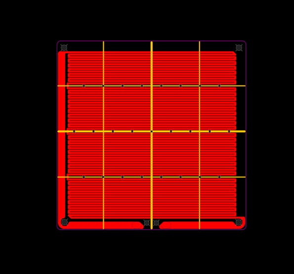
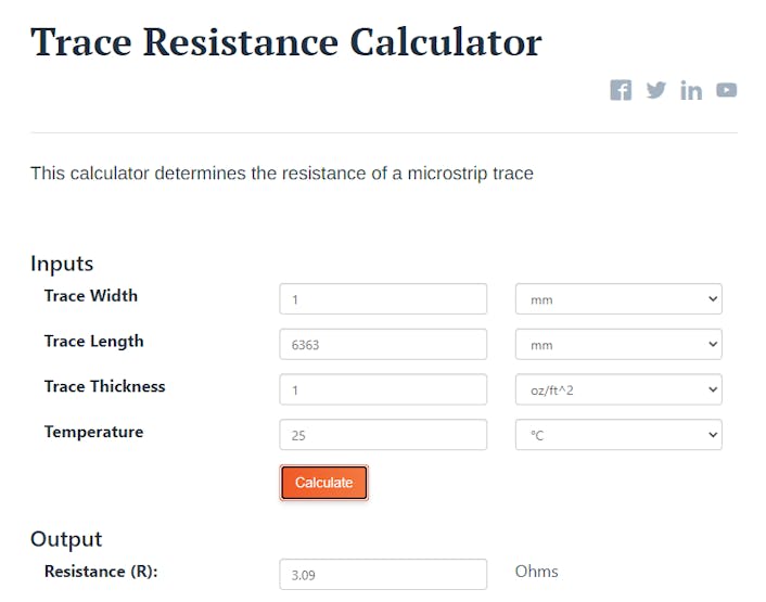
This will be the heated bed. An online calculator shows that the trace resistance will be 3 ohms.
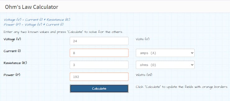
and at 24v it will draw about 200w of power.
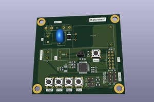
Then I designed the controller circuit. I will use this TTGO T-Display module since it has a builtin TFT display. Along with MAX6675 ic with k type thermocouple. There are two mosfets to control the heatbed and a small cooling fan. After designing the PCB I head over to PCBway for manufacturing the PCB.
Initial Testing:
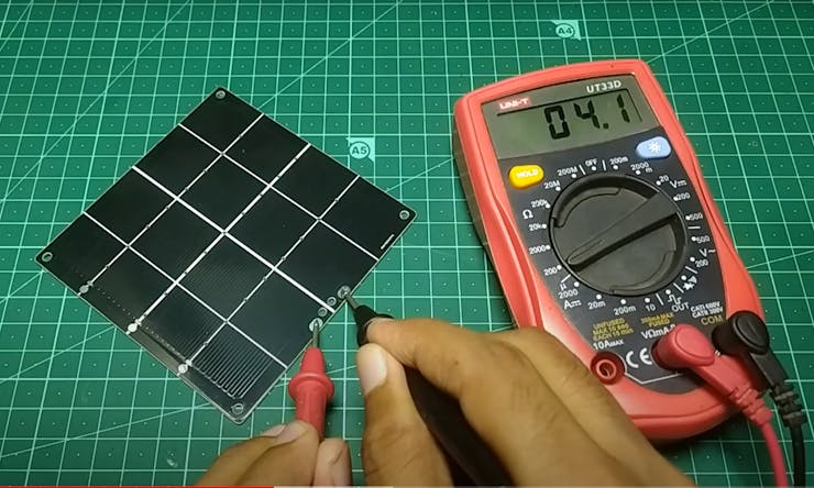
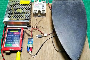
After getting the PCB I first measured the trace resistance and it’s 4 ohms which is slightly bigger than the previously calculated value. Then test the maximum temperature. So at 24 volts it draws about 7 amps of current and the temperature rises to 178 degree Celsius.
At that time the connection was interrupted because one of the wires got disconnected from the PCB. Because the entire PCB was heating up so the solder joint melted. Later I fixed it by using alligator clips instead of soldering the wire directly. But Still I couldn’t reach the desired temperature. So I reduced the trace resistance by shorting the wire and then I was able to reach 230 degree Celsius.
Programming :
It uses PID based temperature controlling which I explained in a previous video. Currently I have two types of solder paste. One is 183 degree SN-PB and the other one is 138 degree lead free type. You can use the reflow profiles in the code if you use the same type or set up a new profile based on the solder paste that you are using. The temperature profile is usually provided by the manufacturer or you can search online.
Final Run :
After powering it up we come to the home screen. Here we can see the current temperature, the heater and the fan states. Then we can choose the reflow profile from the paste option. In the setup we can see more options.
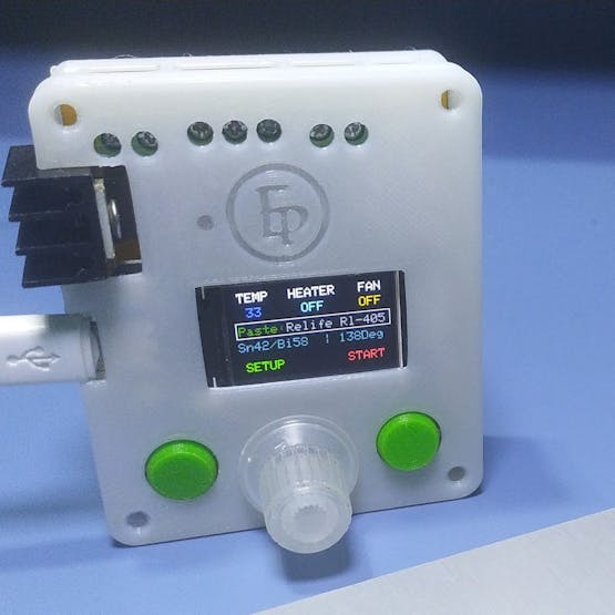
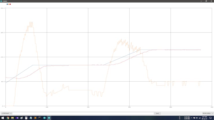
The reflow process starts when we press the start button. Here you can see the graph based on the reflow profile that we have set in the code. Then the heater starts and the PID algorithm starts controlling the temperature. The while line represents the current temperature and as you can see it pretty much follows the defined graph. So the PID works perfectly. I also 3d printed a case for the controller board and these little button caps. And after putting them on our project is complete.So it's time to reflow some PCBs.

 mateuszbor22
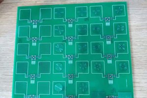
 MG
MG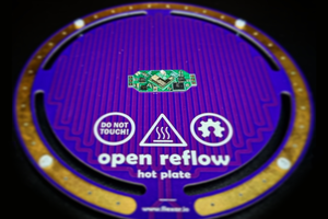
 Carl Bugeja
To create the PCB files, go to KiCad, create a schematic with two jumpers and create a PCB with a zig-zag trace. Cut-paste will be quite helpful.