 Paul McClay
Please click through to the ongoing project #Minamil: a minimal CNC mill !
This project here was temporary for the 2021 HaD Prize
Winning a finalist slot was great and much appreciated! – and done!
Thanks for checking out my project! For whatever brought you here, please jump over to #Minamil: a minimal CNC mill where this project started and continues. If you wish to follow future updates, please follow that project instead of this one.
This project here was created for the #Supplyframe DesignLab: 2021 Hackaday Prize competition, where it won recognition as a finalist. !. Conclusion of the competition completed the life cycle of this project.
════════════════✂――――――――――――――――
This "new" project represents current development of #Minamil: a minimal CNC mill with an overview of prior work curated for entry in the #Supplyframe DesignLab: 2021 Hackaday Prize competition -- without breaking continuity of the main project and leaving behind people who have followed there.
Apologies, dear Hackaday Prize judges. I had all the best intentions to make substantial new final video and additional content, but didn't get it done.
This little CNC mill works well enough to produce an eye-candy demo video:
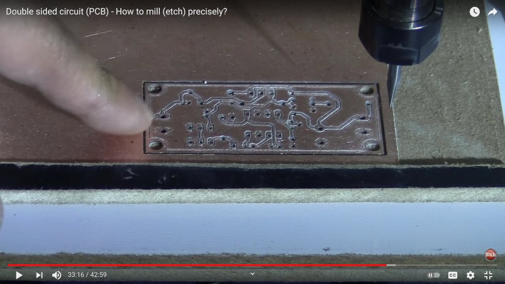
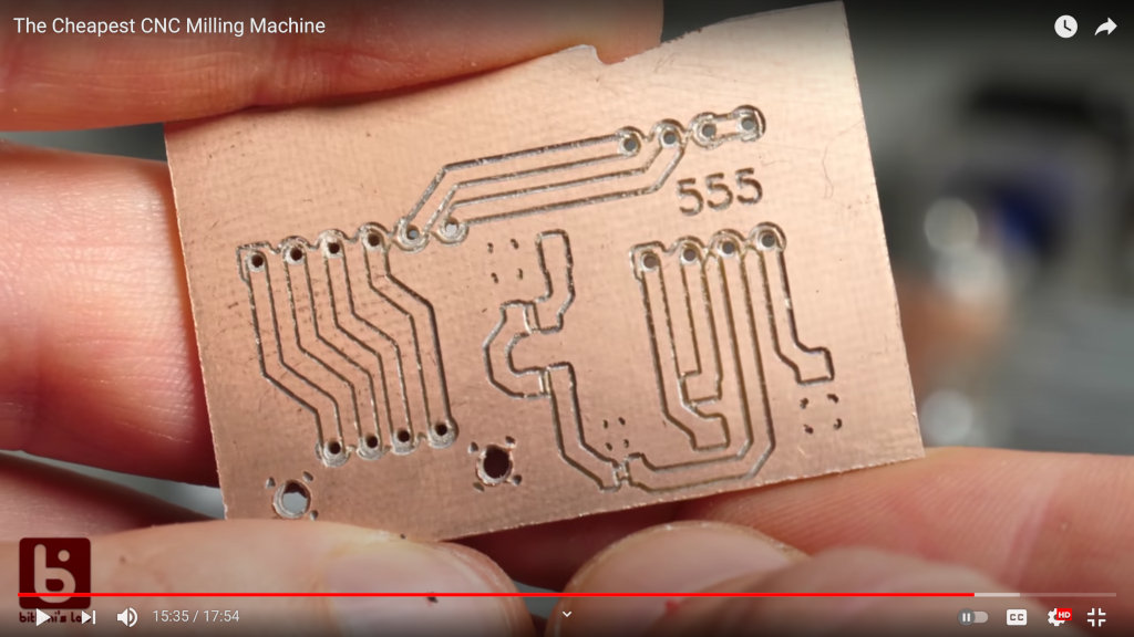
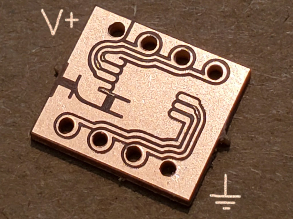
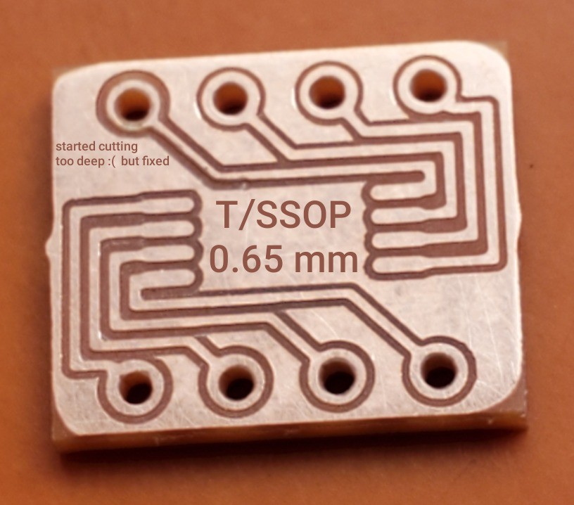
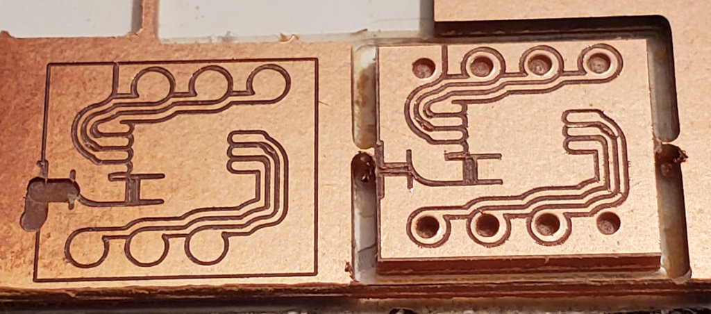
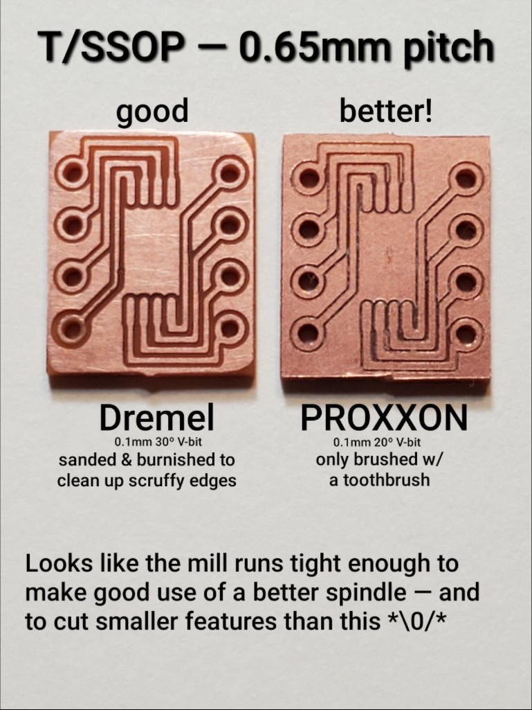
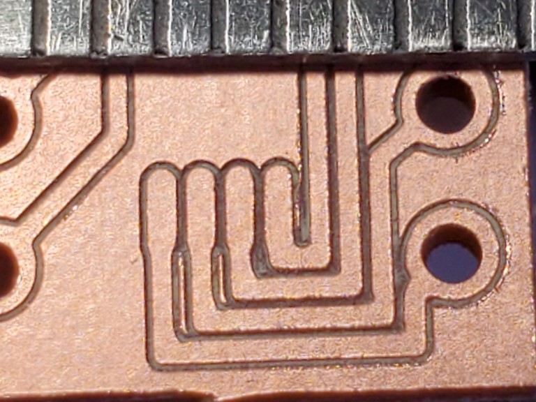
...and mill fine-pitch circuit board traces:
What little CNC mill?
Minamil: a minimal CNC mill
First there was #CDCNC, a highly-constrained just-barely-functional one-off toy built by improvisation with found junk and simple tools.
Here I'm developing an idea that came from thinking about whether or not there is any space between a dumb stunt like CDCNC and a commercially (i.e. efficiently) produced entry level CNC mill.
In contrast to CDCNC, this is about reproducibility from a simple BoM, economical access to laser cutting, and instructions for building your own sub-mini CNC mill.
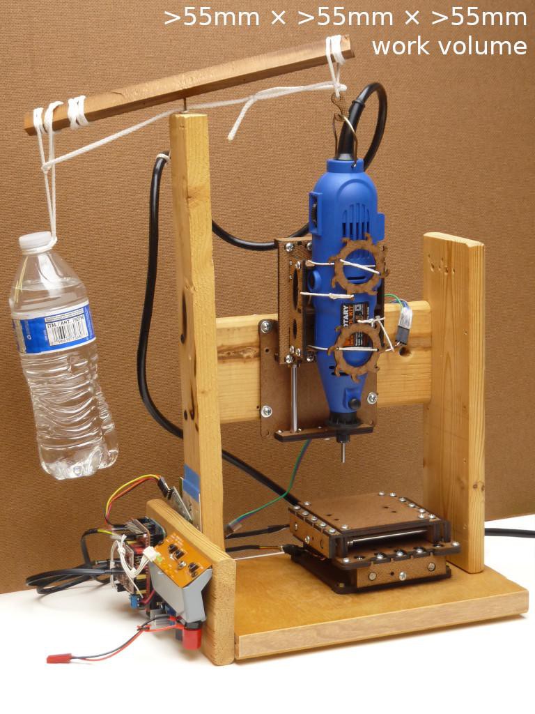
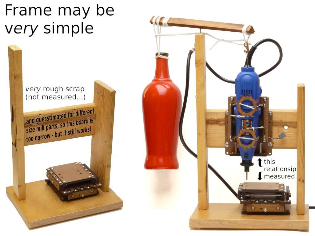
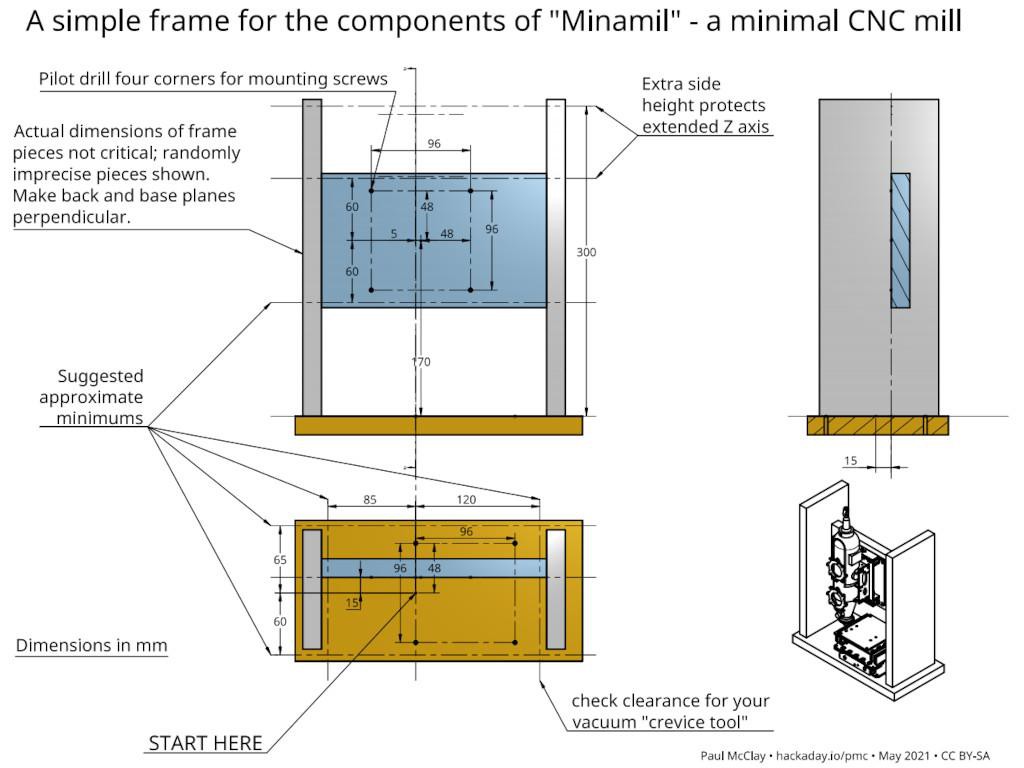
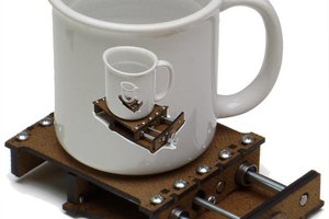
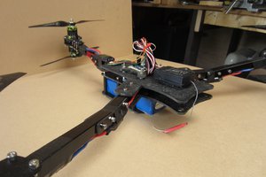
Next there may be #"Desk Accessory" CNC Milling Machine. The lead image montage includes a couple views of the current proof-of-concept frame+enclosure (* with a currently unpublished extended Z axis).
Selected Log Entries
Some of these link back to the mainline project.
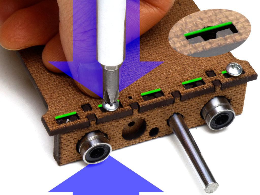
- Build!
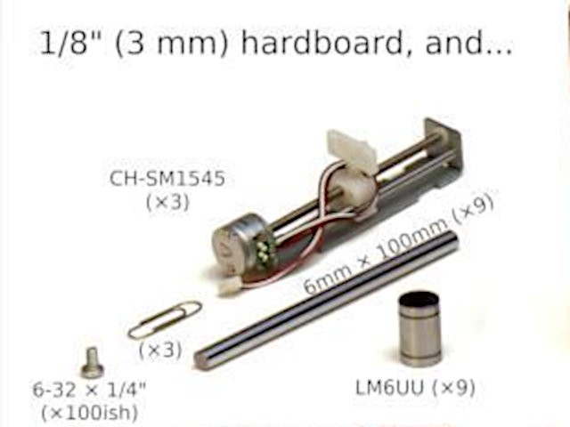
- Parts source / cost notes
- milling PCB (so... MCB?)
- milling aluminum
- material removal rate (MRR) in acrylic
- uh oh... unexpected trouble with self-locking leadscrews
- how it works (could use some updates re later learning)
- compact & convenient packaging
- building blocks: the slide sub-project
- trying intentional interference -- which has worked so far
- first assembly (the eye-candy video)
- first part
- first try with XY & Z
HaDPrize 2021 - Challenge 5 - Reactivate Wildcard
Wildcard: to refresh or redefine the technologies we know and love in order to create a brighter future for all
A technology problem facing people today...
Although we may be getting over it, COVID-19 closures and remote learning have been pretty hard on anything that might have smelled like shop class or hands-on practical education, including opportunities to practice CNC programming and machining.
Personal 3D printing has become common. While laser cutters remain costly to own, their straightforward operation can work well as a commercial service or community resource. Meanwhile, "Subtractive" CNC milling/routing, the CAM part of CAD/CAM for 70 years, remains relatively less accessible. Obstacles include cost, space, mess, and complexity. Potential benefits of access to CNC milling include working more kinds of material with greater precision, and, for tackling the complexity, entree to a valuable career.
...and an idea of what a solution might be
This project aims to significantly reduce the entry cost of personal CNC milling by way of an apparently unprecedented combination of:
- assembly from ready parts vs. fabrication
- lowest cost
- good precision
- table-top use and shelf storage in home vs. fixed installation in garage or shop
And also some...
Read more »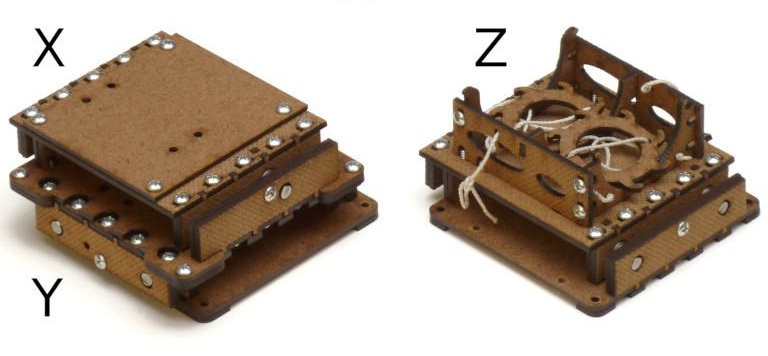


 KMD
KMD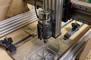
 Peter Buckley
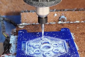
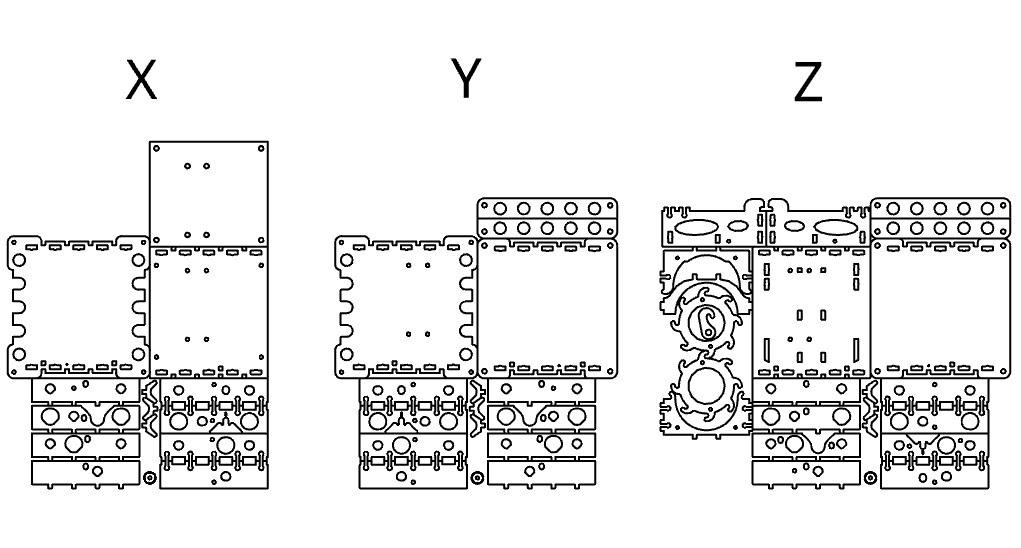
Do you have any suggestions for getting those parts cut? Does anyone have suggestions for an online vendor that could cut and ship these parts?