 Ahmed Oyenuga
One of the things I’ve had to do a lot of recently is designing and building PCB’s, I had been looking for a way to make my PCB assembly process more efficient, and it wasn’t until I saw unexpected maker’s video on the pick and place turntable that he uses to populate his prototype PCB’s that it all came together, the concept of his design provided the bases for which I used to build the Pick-N-Place Wheel, so I’ll like to give a huge shout out to Sean from unexpected maker for sharing his idea and for inspiring the Pick-N-Place Wheel. Watch his video here.
Project Video.
What is it?
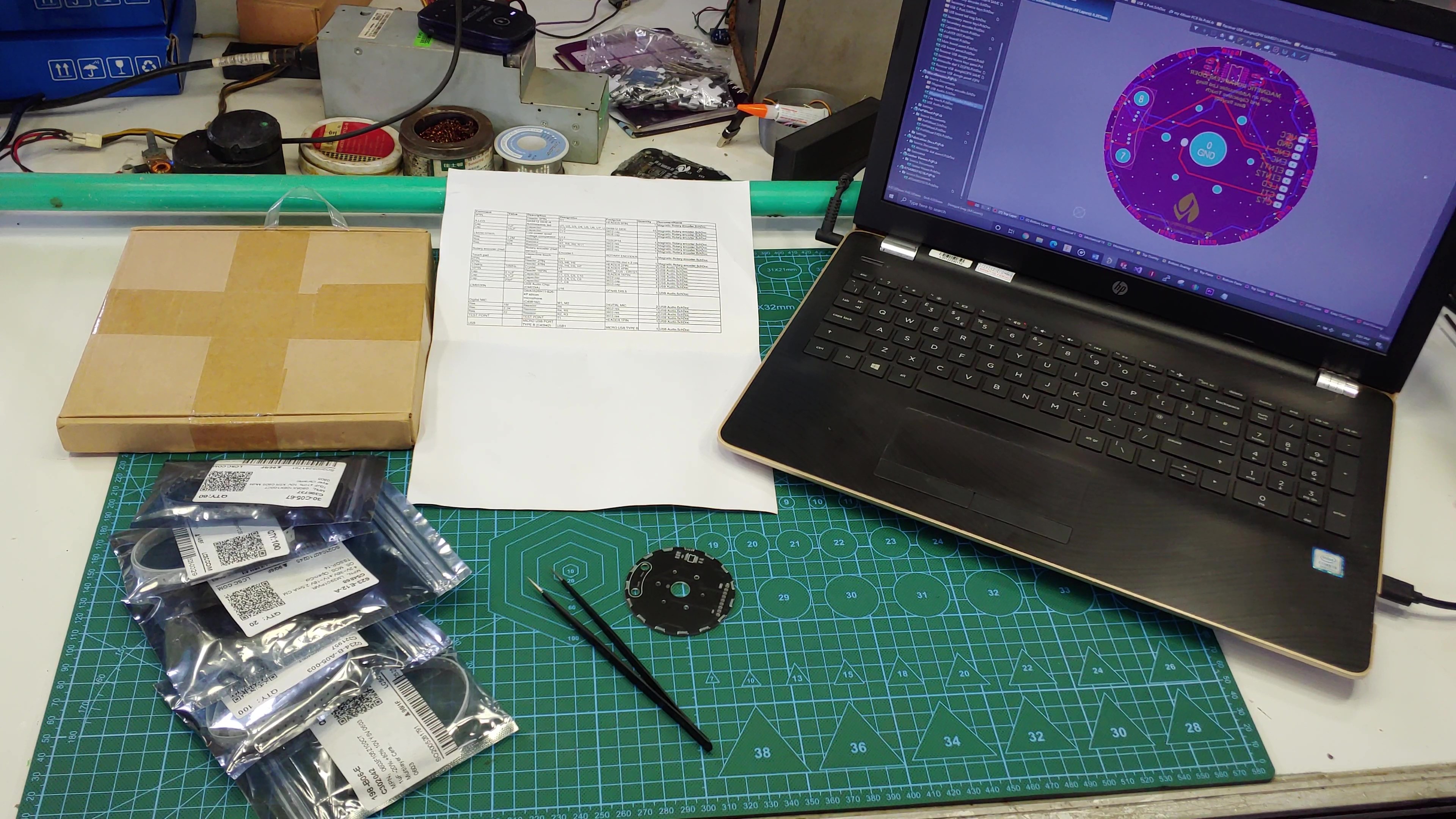
If you have ever hand assembled a PCB, the setup shown in the picture will look familiar to you, to populate a PCB, I would normally have all the components on the table, along with the pre-pasted PCB and a spreadsheet for the board I want to populate, this spreadsheet will usually contain important information like component value, footprint, designator and any other information that’ll enable me to accurately place the components. I would often also have my laptop close by so I can confirm the position on the board where specific components should be placed. With this process I usually avoid any placement errors, but the process can hardly be called efficient, especially if I have to assemble multiple PCB’s…so, my goal for the Pick-N-Place Wheel project is to combine all the elements associated with manual PCB assembly to form a system that is as seamless and as efficient as possible.

The Pick-N-Place Wheel is not just a 3D printed device, it’s a combination of three main elements: The 3D printed wheel itself which is the hardware, the rotary encoding and slot indexing; the electronics, and the control software in the form of a desktop application. The Pick-N-Place Wheel will not function as its intended without these three elements.
THE WHEEL

The wheel’s function is primarily to hold your components in indexed slots for when your populating a PCB, but it also doubles as the permanent storage for those components, thanks to the built in twist locking mechanism.

The wheel’s transparent top cover has a few flexible 3d printed tabs glued to it, this tabs fit into matching slots on the wheel, so that when you turn the top cover in one direction it creates a 1mm separation from the wheel (opened state), allowing the wheels to rotate freely during board population, and when the wheel needs to be stored away, the cover can be turned in the other direction which lowers it back down unto the wheel (closed state), sealing the components in their slots and preventing them from falling out or falling into another component’s slot. So instead of keeping components in the anti-static bags that they came in, the Pick-N-Place Wheel can be used to index and store them.
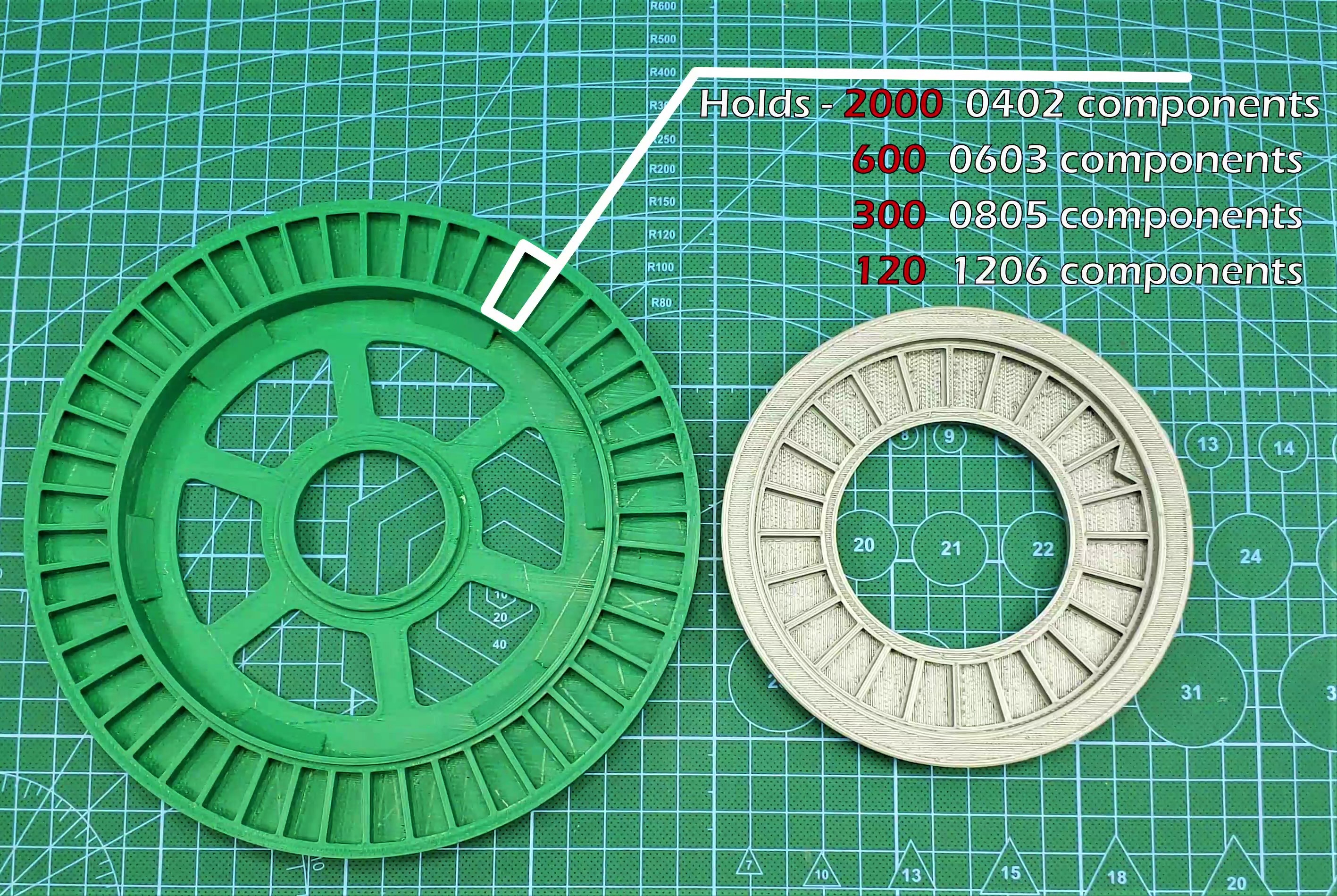
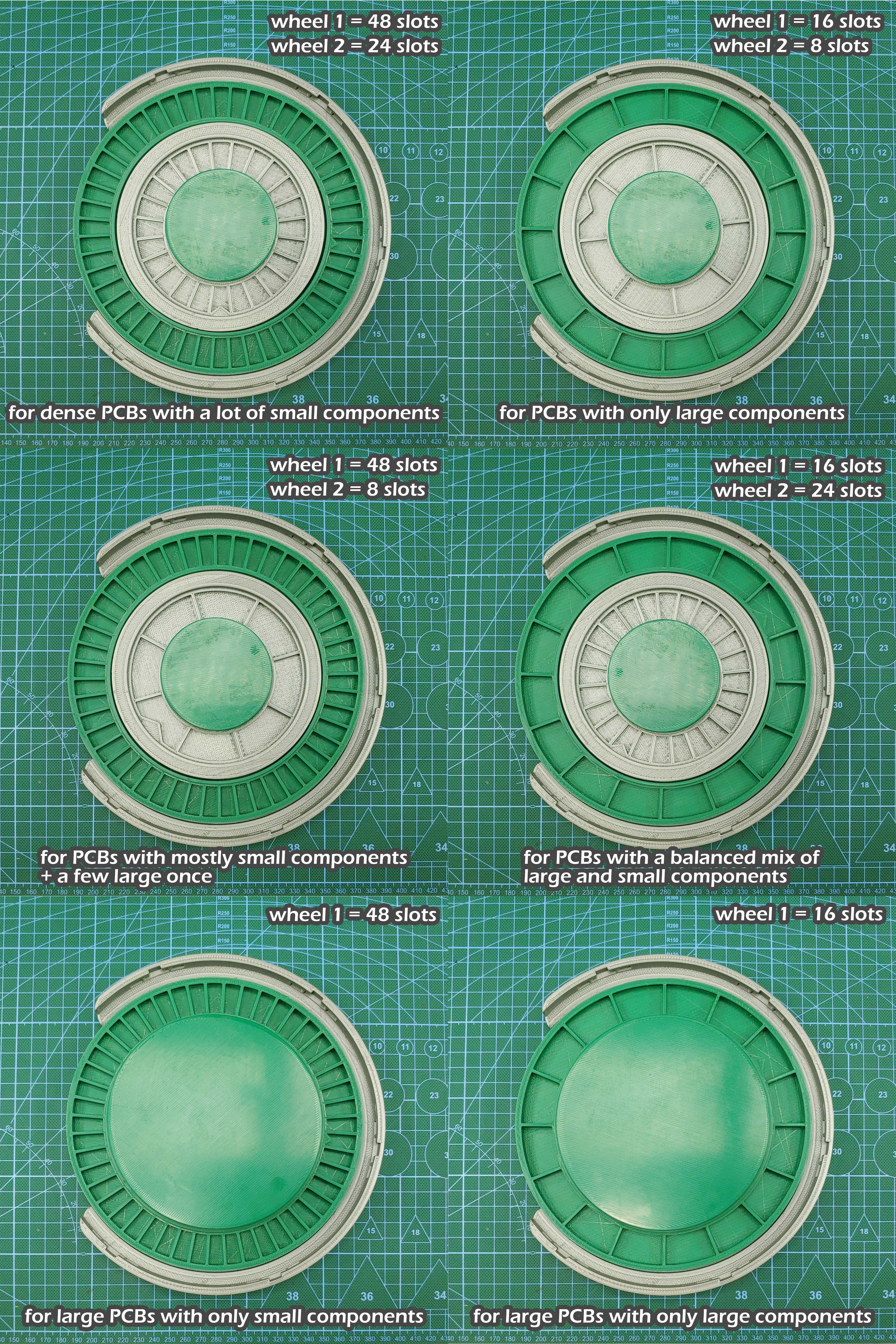
The Wheel is designed to hold two separately encoded wheels, one large outer wheel identified as wheel 1, and one smaller inner wheel identified as wheel 2. The image above shows the typical capacity of the wheel’s slots, each wheel has two versions, wheel 1 has a 48 and a 16 slot version, and wheel 2 has a 24 and a 8 slot version, this wheels can be combined in multiple ways to suit various types of PCB projects, the wheels with the higher slot counts are designed to hold a lot of small SMD components, while the wheels with the bigger slots are designed to hold bigger parts, like usb ports, leds, power inductors or connectors.
The placing surface where you’ll place the board you want to populate also has two versions to accommodate different board sizes. The image below shows all the possible configurations of the Pick-N-Place Wheel and their intended project types.
THE ELECTRONICS
The Pick-N-Place Wheel is built around wheel encoding and indexing which is facilitated by the electronics.

Each slot on the wheel has an index, this index is used to identify and place the components that are stored in them, this is possible because the Pick-N-Place Wheel itself is one giant rotary encoder, or more accurately contains two rotary encoding wheels. The wheel uses the magnetic rotary encoding method that I developed a few years back, it’s the same rotary encoding that’s featured in the Ahmsville dial project, you can read about it here.

Each wheel features a number of magnets attached to its base which are configured with alternating poles, the magnets encode the slots on the wheels, so the number of magnets on each wheel is proportional to the number of slots on the wheels. The accompanying board has four hall effect sensors on it, which are used to read and interprets the analog values form the magnets as the wheels rotate, the resulting encoding data is how the slots get their indexes.
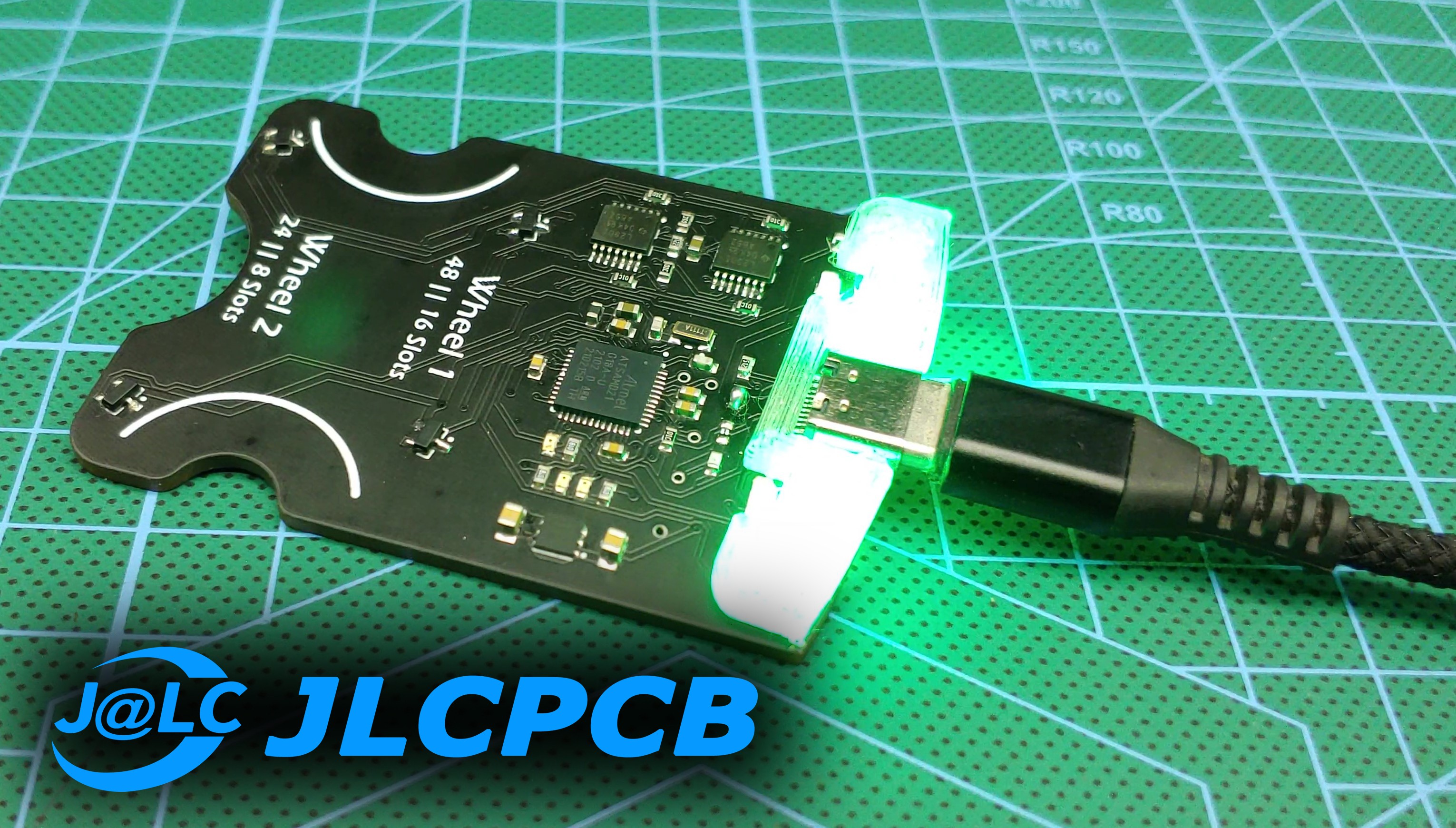
The board is a typical microcontroller board, it features four hall effect sensors for reading the analog values from the wheels, two analog comparators for ensuring accurate encoding of the wheel’s rotations and two addressable leds that shows the status of the wheels, the board is controlled by the SAMD21G chip, the same as the Arduino zero boards.

To keep with the modular theme of the Pick-N-Place Wheel, the board is also detachable, which means you can make as many wheels as you like, and you’ll really only need one board, since you can easily swap the boards from one wheel to the other, the board also supports all the different physical configurations of the Wheel.
THE APPLICATION
The Desktop application is the most important part of this project, the Pick-N-Place Wheel is all about simplifying the manual pick and place process and the software is integral to achieving this goal.
Whenever you’re populating a PCB, there are two main things you need to know, the first is the specifications of the component you’re about to place, like its value and its footprint, the second thing you need to know is the location on the PCB where the component should be placed, this is where the software comes in, it uses the actual pick and place data generated for your specific board together with the image of the board to create pointers that tell you where and how to place parts on the board, this in conjunction with the position information from the wheel is what constitutes the complete manual pick and place solution.
For every PCB you design, you’ll usually have the option to generate a pick and place file, this file will contain information like component name, value and footprint but most importantly, it will contain the x and y position for all the components on the board. The second thing you can easily generate from your PCB design is a 2d image of the board, most PCB design software’s will allow you to preview your PCB in 3D, from this realistic 3d view you can easily generate an image that accurately represents the board, the image doesn’t have to be the same size as the board, it just needs to be in the same aspect ratio as the actual board, when you load the pick and place csv and the board image into the app, it reads all the data from the csv and it also displays the image of the board.
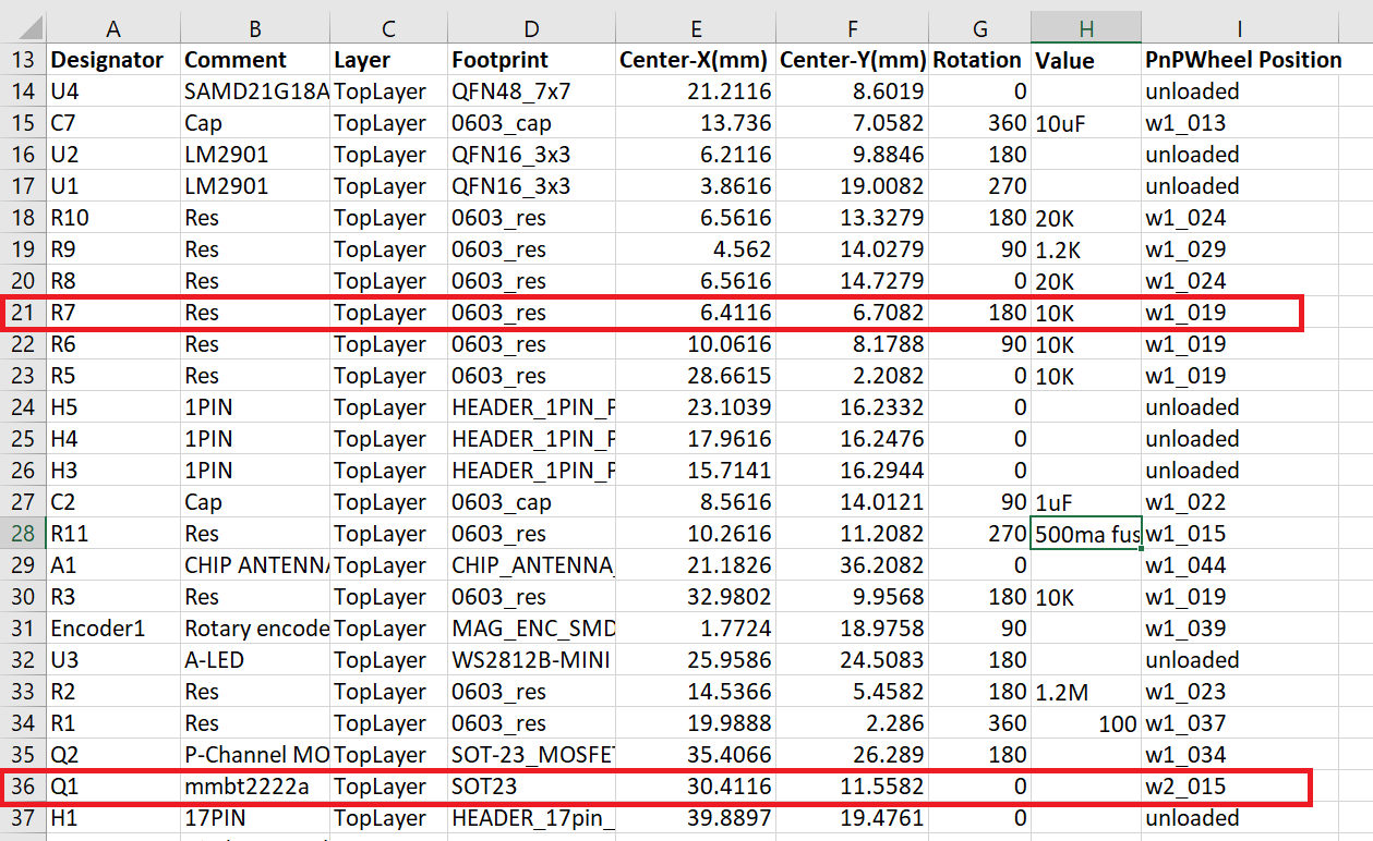
Whenever you load a new csv into the app, a new column is created inside of that csv, this column is titled PnPWheel Position, this column is where the slot indexes for the components are stored, the position information from this column is also what connects the physical Pick-N-Place Wheel to the app. so you’ll notice from the image that some of the rows say “unloaded” indicating that those components don’t have an index in the Pick-N-Place Wheel, the components that have been loaded into the wheel will have their index shown under the column, so row 21 for example tells me I have 10kohms 0603 resistors in slot 19 of wheel 1 and row 36 tells me I have 2222A transistors in slot 15 of wheel 2. All the information used and displayed by the app comes from this one csv file, the app only makes it easy to visualize and manage all the data in relation to the specific board.

During the actual pick and place process, the Pick-N-Place Wheel connects to the app through the serial port, and sends the slot indexes to the app as a string through serial communication, the app then uses that index to pull all the information about the component from the csv, and then shows you everything you need in order to confidently populate your desired PCB.
Download the full Build and Setup instruction document.
Links:
Github repository – https://github.com/ahmsville/Pick-N-Place_Wheel
Download Pick-N-Place Wheel App – https://github.com/ahmsville/Pick-N-Place_Wheel/releases/tag/installer
Download 3D Files – https://drive.google.com/file/d/13K5KHEiYU0XfNlAly5jGHfDs_ekXsjdr/view?usp=sharing
Buy the Pick-N-Place Wheel Board - https://www.tindie.com/products/24720/