 Blecky
The main focus of this project was originally to create a multipurpose ticketing system utilising as many open source tools as possible. This could be used in any way for things such as event management, transportation, space travel etc. To reduce the scope I have decided to create a modular system that first focused on transportation, but could be modified easily to perform other tasks. For the purposes of the Hackaday Prize, only the card reader hardware, database connectivity and simple zone management (GIS web service) will be implemented. This working proof of concept will enable further development as time goes on.
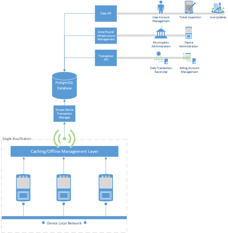
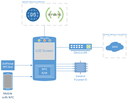
System Block Diagrams
Overall System:
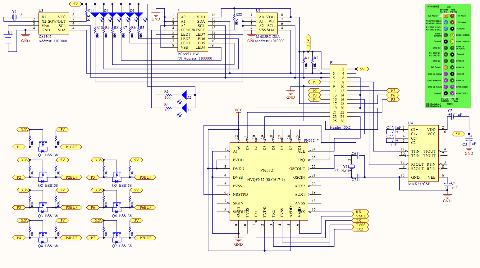
Card Readers:
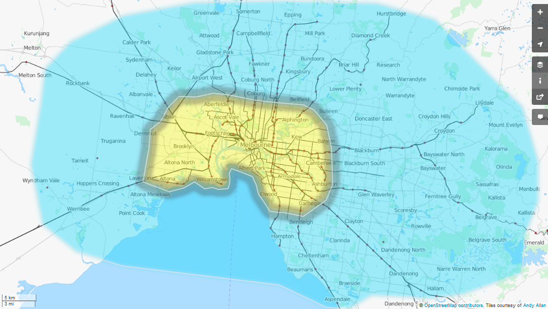
Web Management:
Licenses
| Name | License |
| Django | BSD License |
| GeoDjango | BSD License |
| Python | PSFL |
| Raspbian | GPL (mostly) |
| PostgreSQL | PostgreSQL License |
| PostGIS | GPL |
| py-postgresql | BSD License |
| cython | Apache License |
| NXP NFC Software | Licensed for use with PN512 Only. "This NXP Semiconductors IC is ISO/IEC 14443 Type B |
The OURTicket project and all of it's sources is released under GPL.


 Pierre-Loup M.
 burkethos
 Dave Vandenbout
 Sander van de Bor