 Michael Laffin
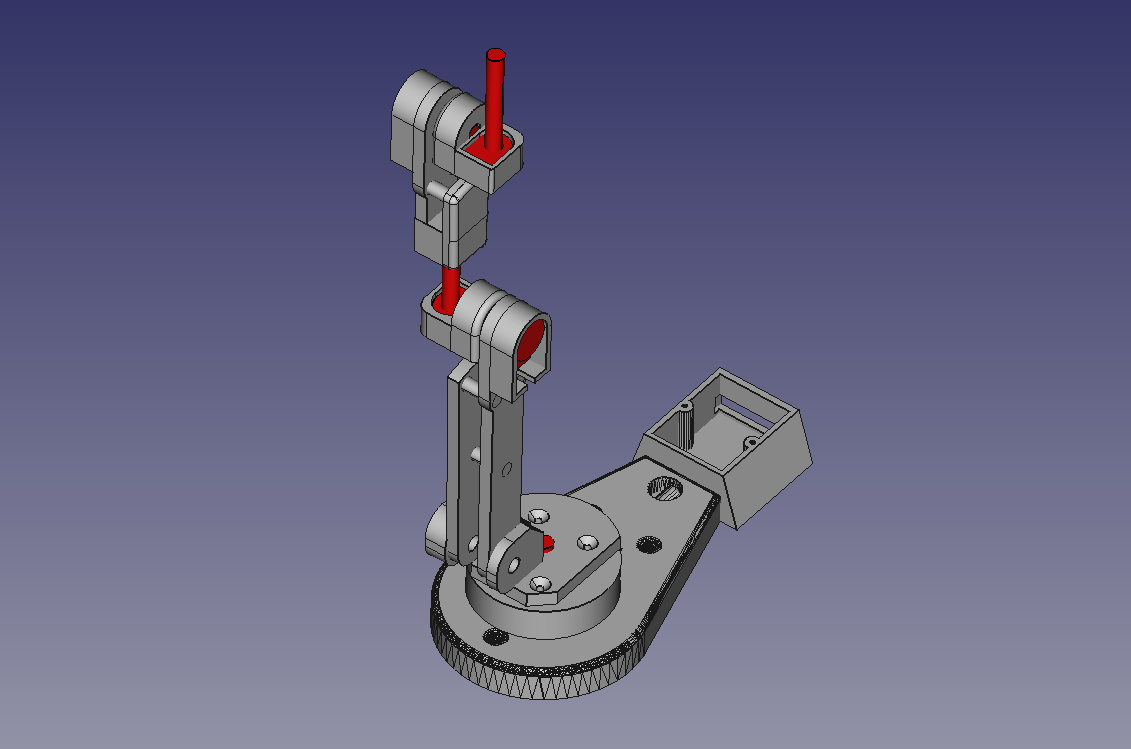
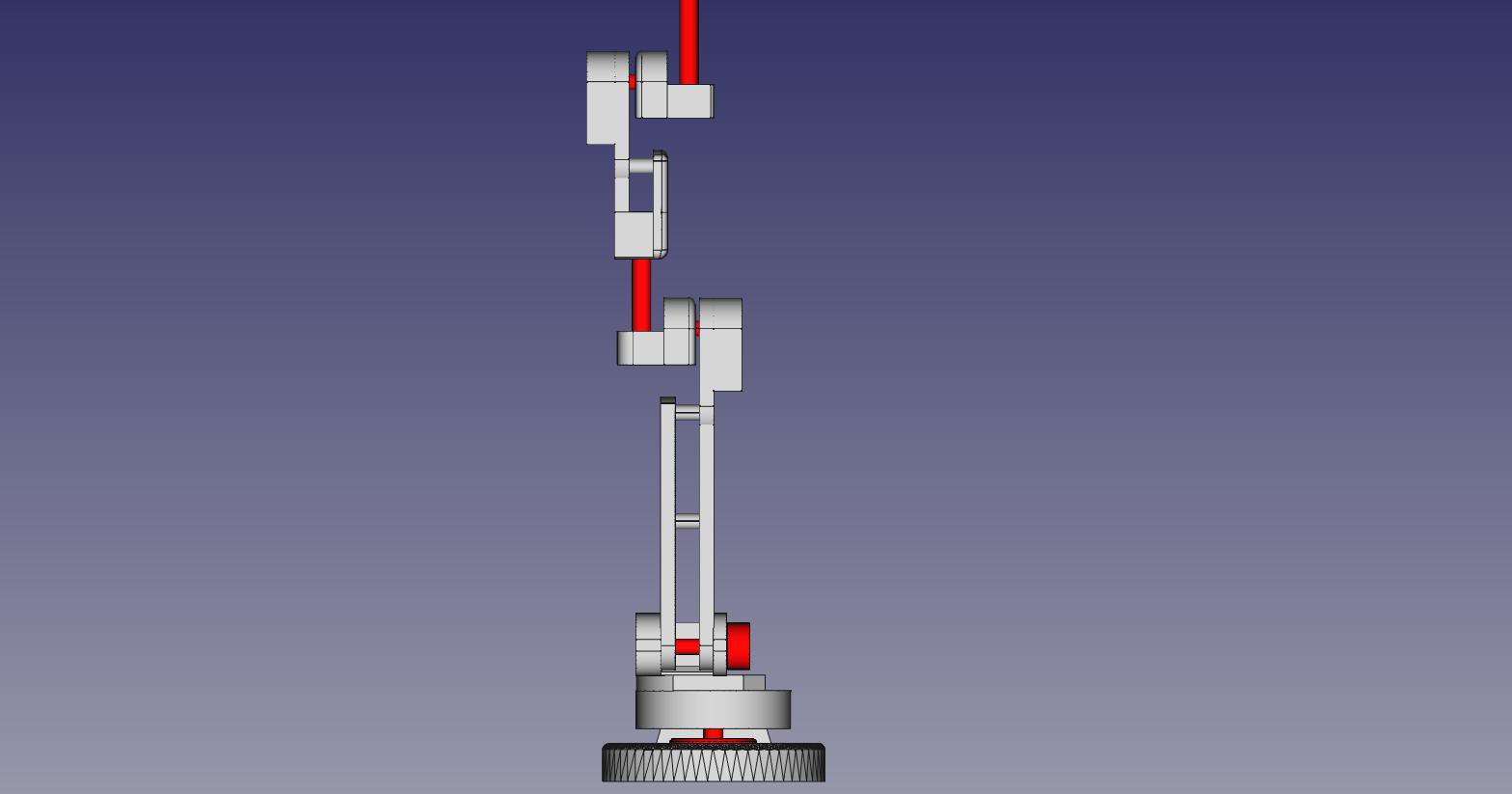
The mechanical design of the controller arm assembly was done using the open source modeler FreeCAD. Although it may not appear similar, the structure is dimensionally congruent to the full robot arm. The potentiometers are shown in red to increase visibility, and printed components are shown in grey. Full CAD model is available here. To print individual components, simply select the part from the model list and export as an STL to be printed.
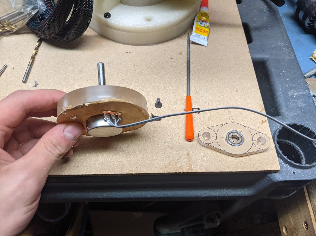
The spacer plate shown below was machined out of polycarbonate, however it could be printed in PLA just as effectively as the other parts. The J1 potentiometer shown below was eventually replaced with this component. Both of these are overkill electronics for this application, but when using the shaft directly in the joint I primarily want a mechanically robust part.
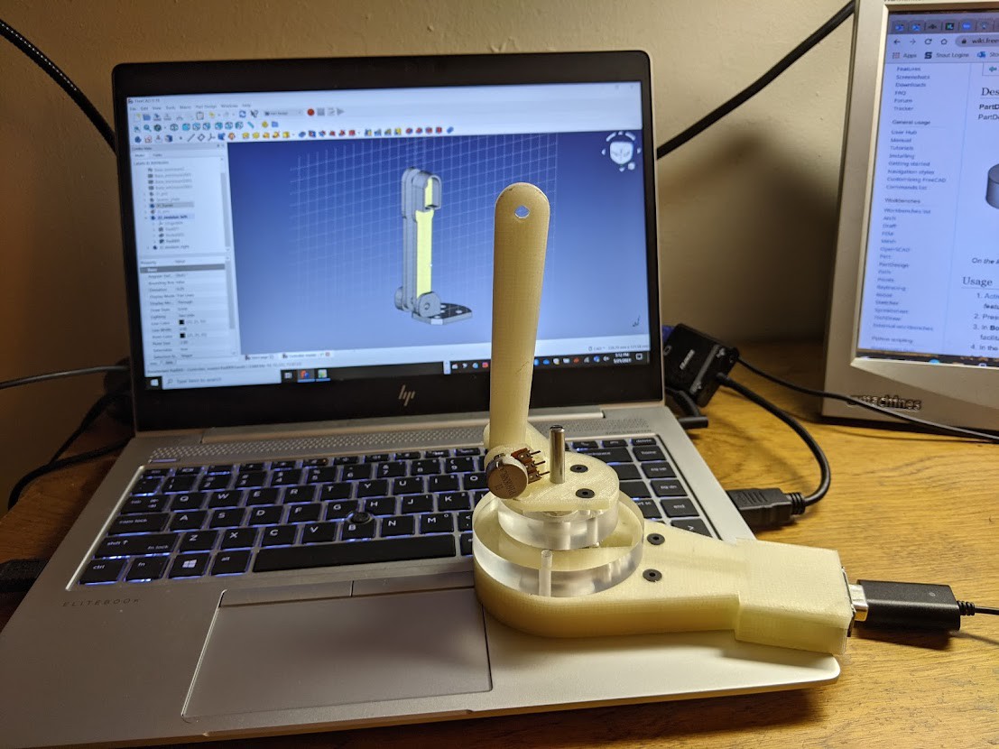
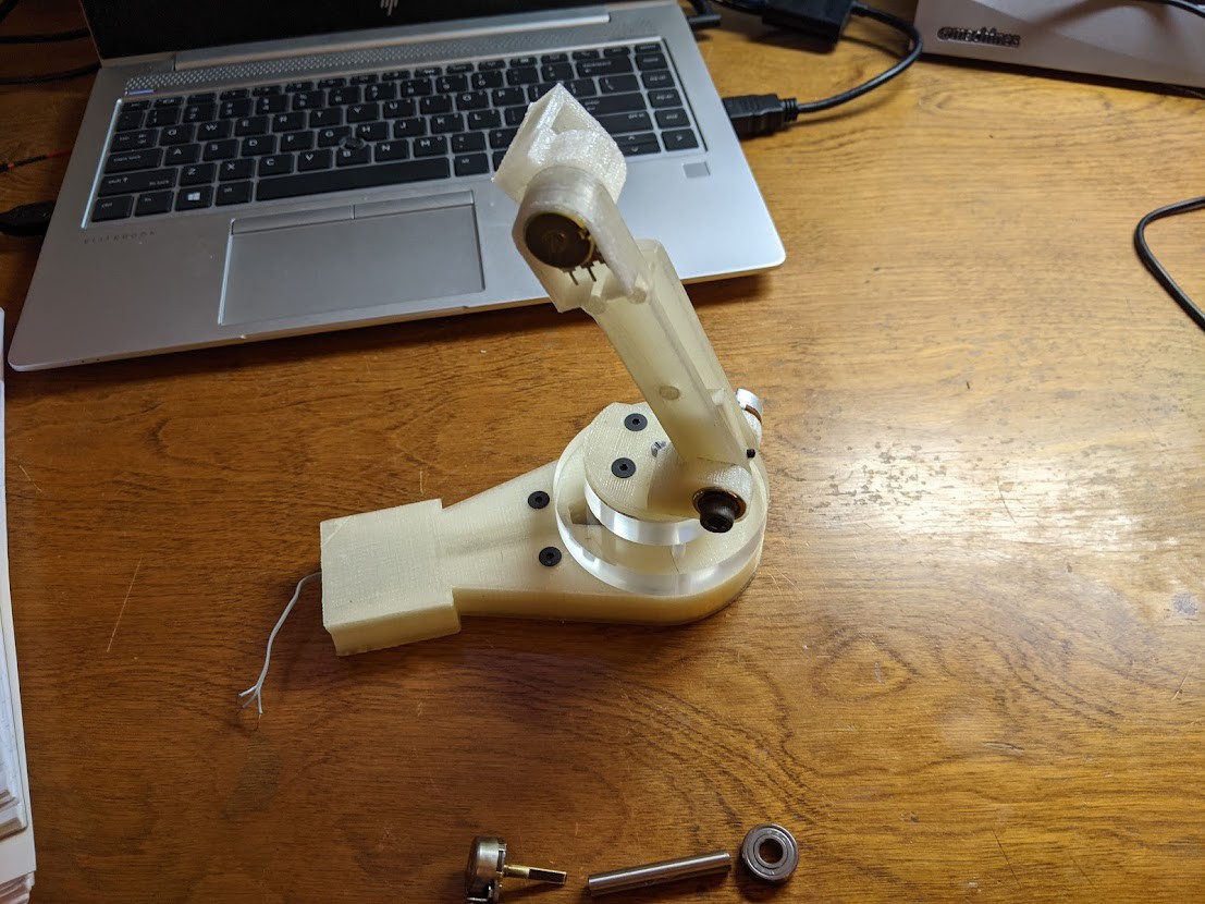
Beginning the design of the arm. The methodology that I used was to basically design the most minimal solution, and then immediately print and test the operation. After several iterations I could usually move on to the next joint within the arm with reasonable confidence. I still want to modify several parts of the design to control joint stiffness on J3 and J1.
Mechanical progress up to the J3 hinge. You can see how I threaded the wires for J1 through the base. A hole was later drilled into the base to allow wires from the other potentiometers into the rear of the wire housing.
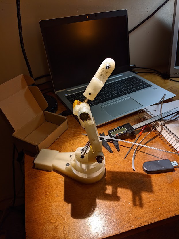
J4 hinge completed. I added a set screw to allow for vertical adjustment on the J4 link. For most joints the controller has a larger range of motion than the actual robot arm, but this can be compensated for in software.
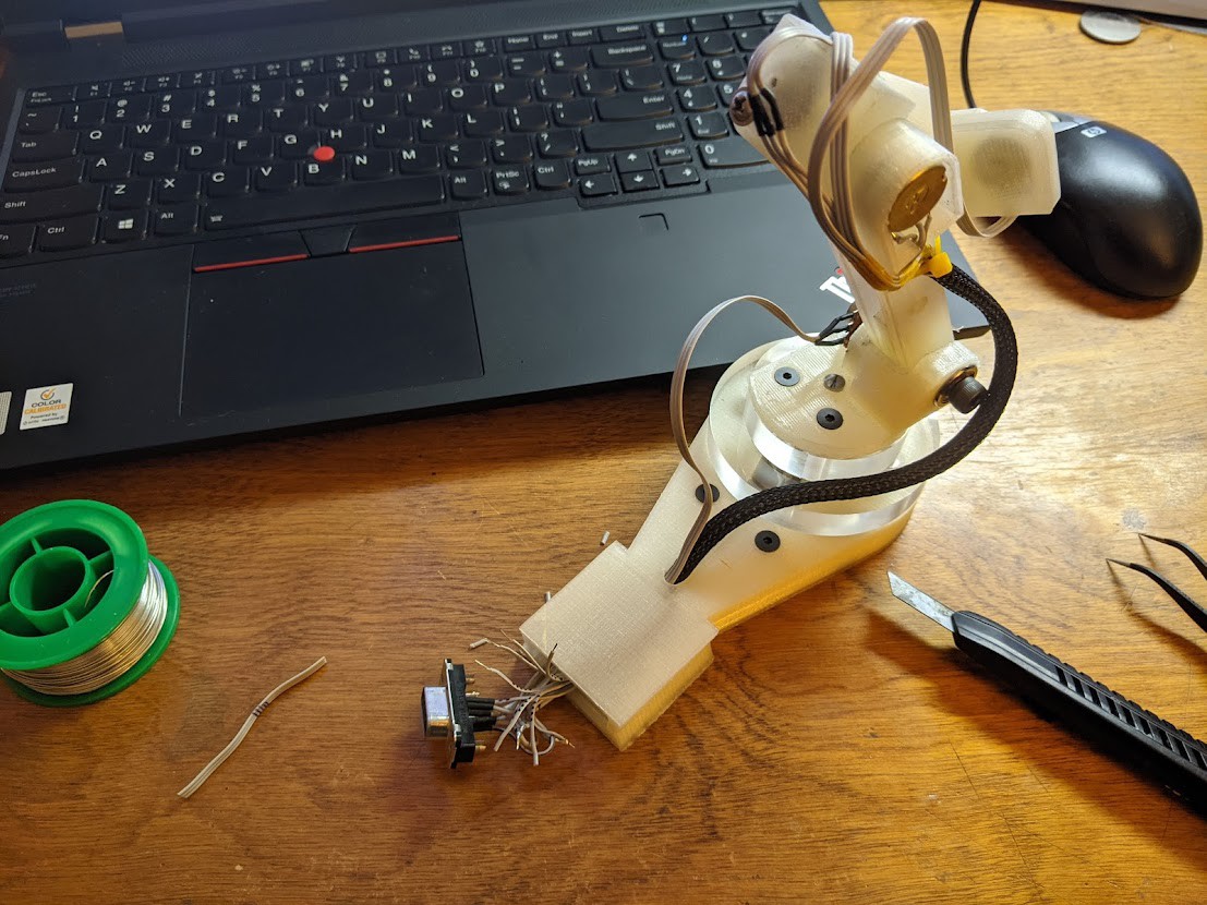
Soldering ribbon cable to the VGA connector in the base of the controller. I decided to use this connector simply because it contains a sufficient number of conductors, and I had several on hand already. Each conductor is marked with tics from a Sharpie, and heat shrink tubing is used to insulate.
Functional arm shown below. The ribbon cables were grouped together using kapton tape and 1/4" plastic wiring harness. Ideally all of these cables could be harnessed within the body of the arm to reduce clutter in the final product.
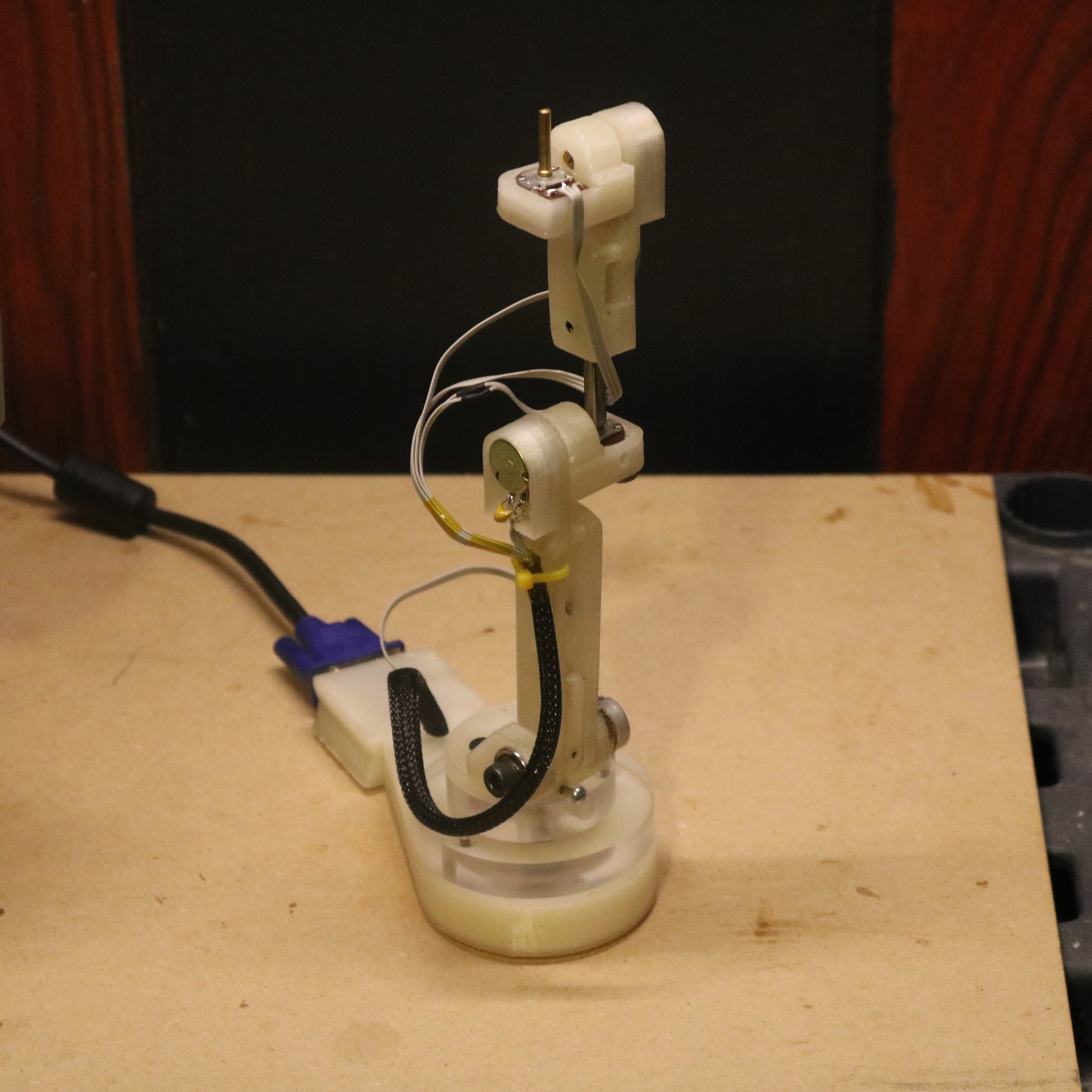
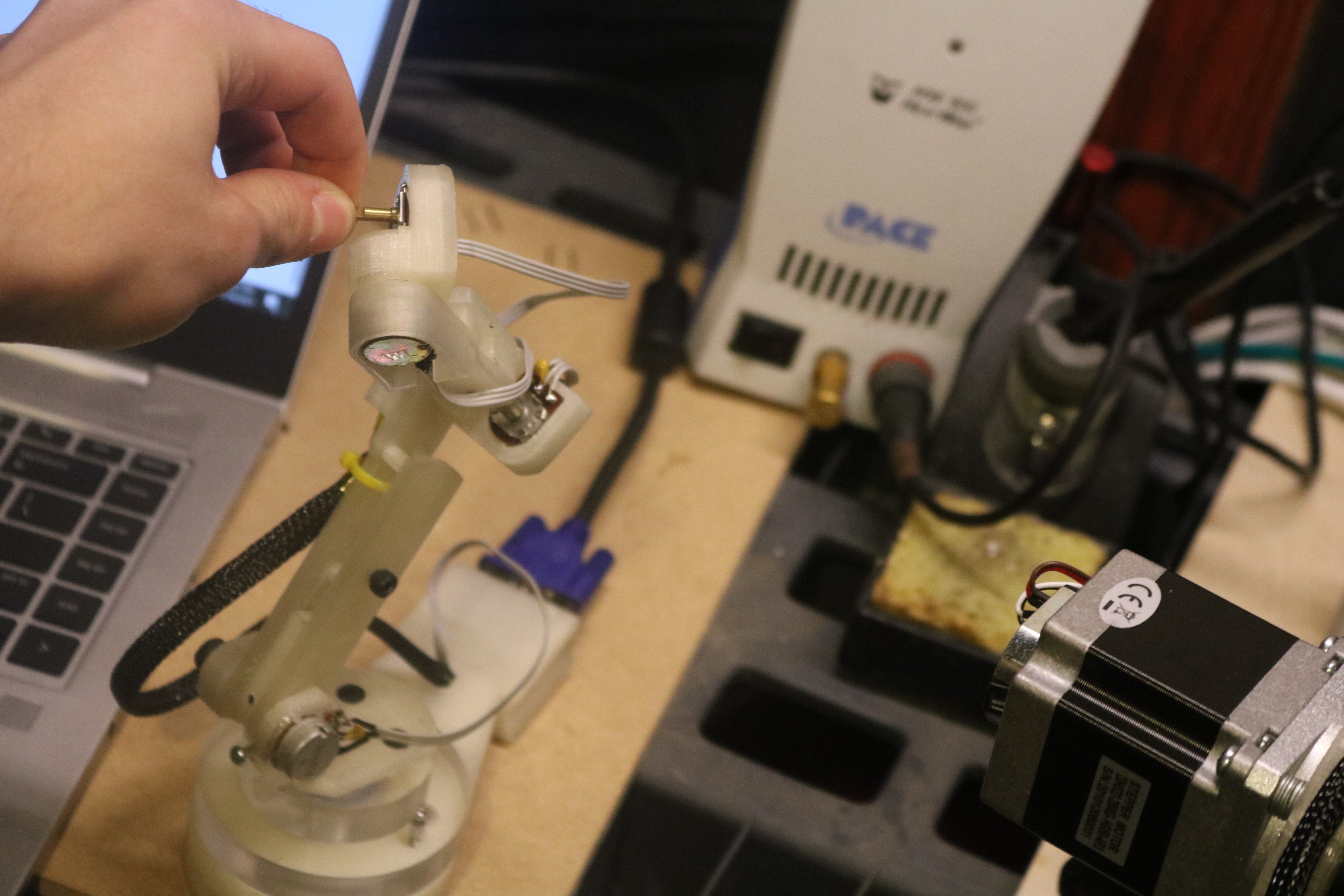
Initial testing of full controller arm. The J6 potentiometer shaft has six degrees of freedom and can move in any position within the range of the arm.
Discussions
Become a Hackaday.io Member
Create an account to leave a comment. Already have an account? Log In.