 Michael Laffin
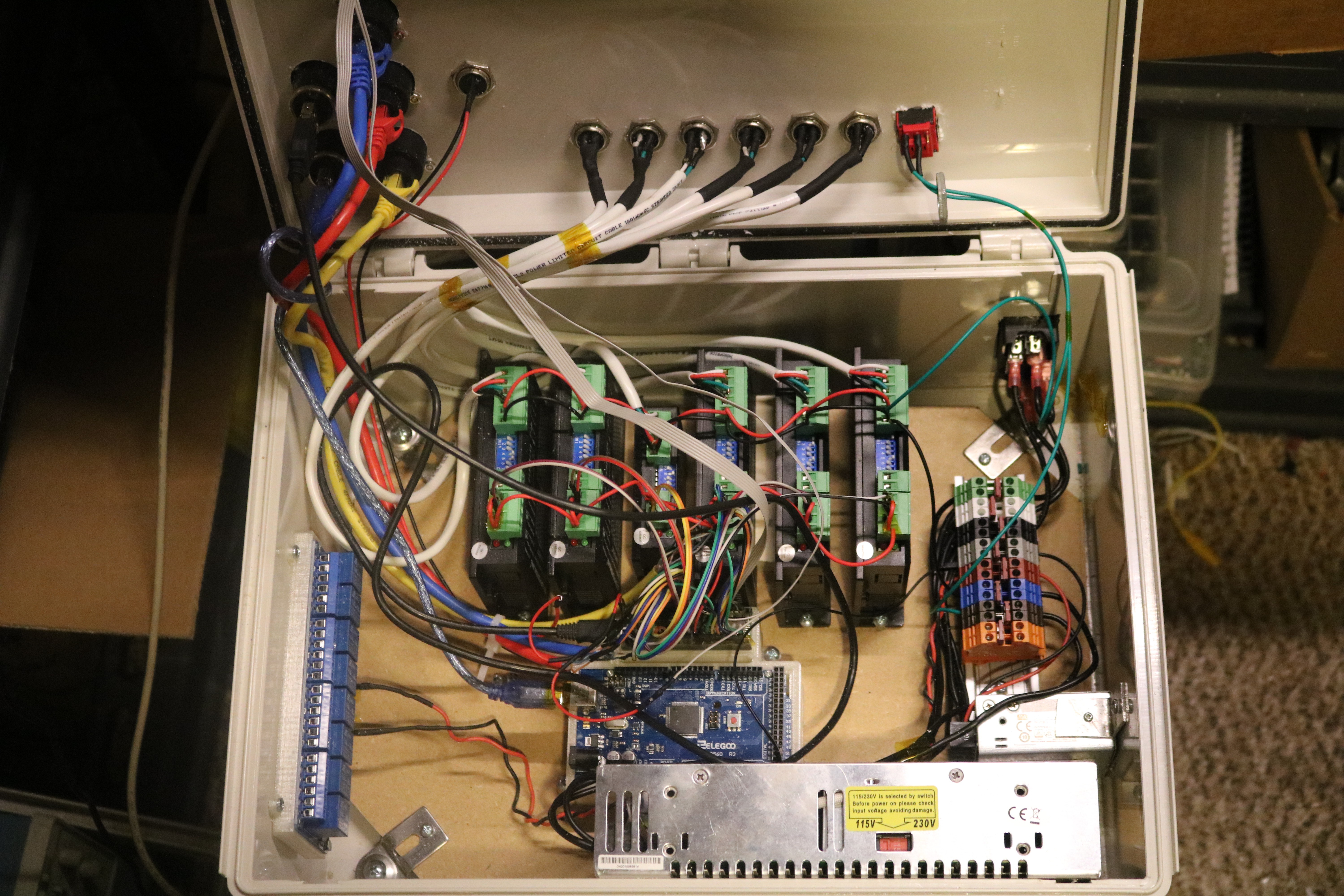
An inside look at the controls enclosure. Mains voltage is fed in the right side inside the box and a DIN rail splits and connects two switched-mode power supplies. The larger supply on the bottom is 24V 10A for driving the stepper motors. The smaller power supply is located directly above and supplies 5V lines for the microcontrollers and accessories. The DM542T and DM320T drivers are mounted vertically (J6-left to J1-right).
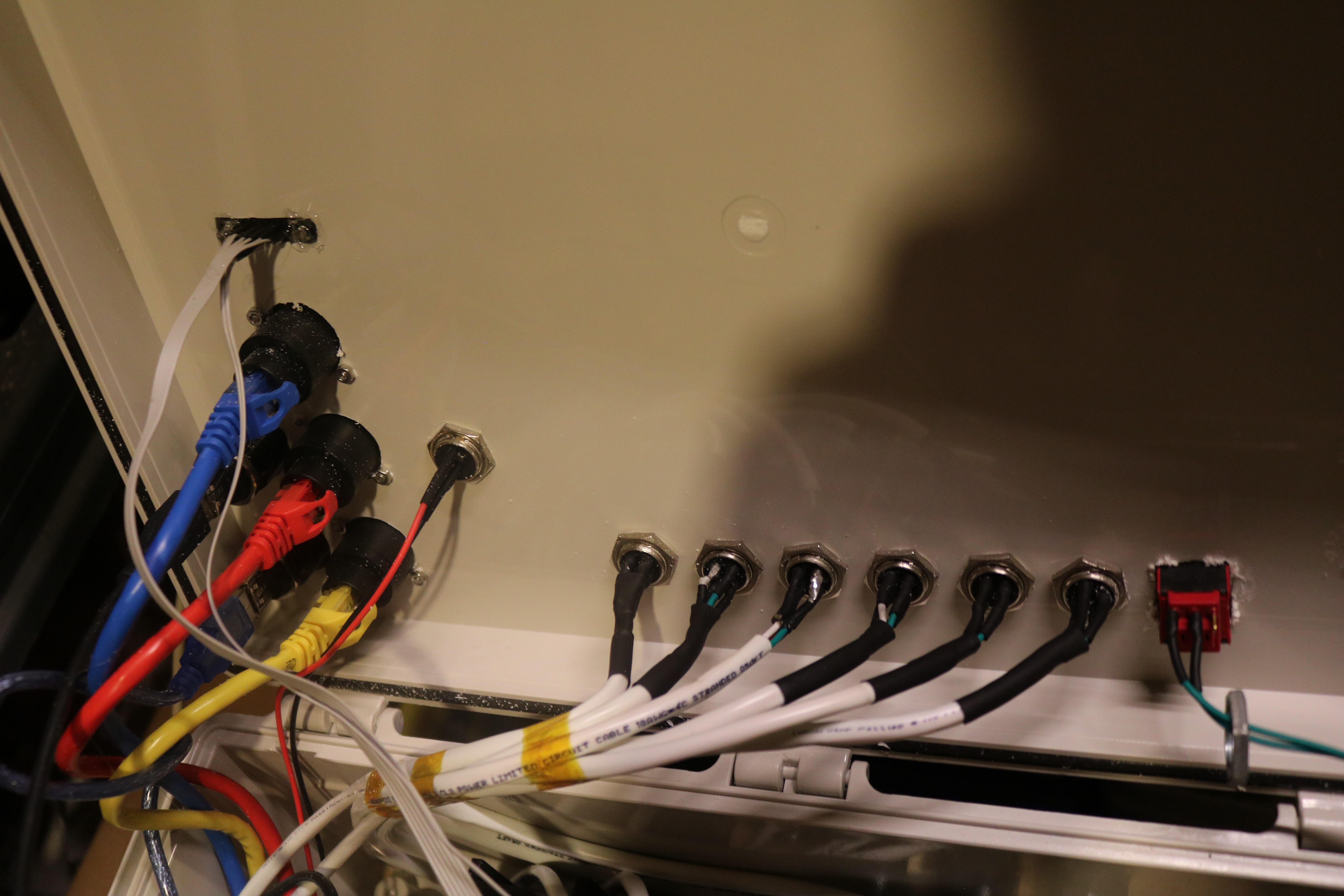
Close-up on the cable feedthroughs on the lid of the enclosure. The ribbon cable on the top left is for the controller arm, the CAT9 cables are used for high-speed encoder transmission, and the motor power cables are spaced horizontally on the bottom. On the far right there is an additional safety switch for the whole system.
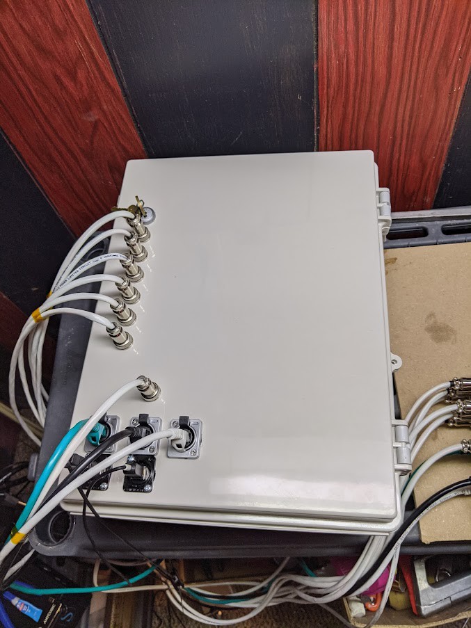
An exterior view before the VGA port was added. I also ended up removing the key switch for a simpler rocker switch.
Discussions
Become a Hackaday.io Member
Create an account to leave a comment. Already have an account? Log In.