 sherwin-dc
Introduction
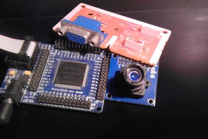
As part of a larger college group project, I had to program an ESP32 to be a control center for an autonomous rover. The ESP32 was meant to take input from an FPGA that processed images from a mounted camera, make movement decisions and also wirelessly communicate with a remote web server. However, I wanted to go one step further and stream video from the FPGA camera to the web server, through the ESP32.
Although both the ESP32 and FPGA has support for UART, SPI and I2C, I decided to try sending video images using the Inter-IC Sound (I2S) protocol instead. I had found a few projects here on Hackaday that specifically used I2S on the ESP32 to output video or drive a display, but could not find anything online about inputting video with I2S. (The link also has a good explanation of how I2S works)
Of course, the ESP32 comes with a camera driver that uses I2S under the hood, but only a few specific camera modules are supported, with no documentation on how it functions. Furthermore, this requires many pins on the ESP32 (8 pins for pixel data + HSync and VSync + XCLK + pixel CLK = 12 pins excluding camera IO pins).
Fortunately, I was able to use just 5 pins by converting video signals into I2S signals. The basic idea is that I2S was designed to transmit words of data bit by bit, thus only 1 pin is used for data. The other signals are:
- I2S bit clock, SCK
- I2S word select clock, WS
- Clear-To-Send pin to signal to the FPGA that the ESP32 is ready to receive another video frame
- Master Clock, MCK, driven by the ESP32
Setting Up I2S

I2S has both a bit clock (SCK) and a word select clock (WS). I2S was originally designed for transferring digitally-sampled sound signals, with each sample having a certain word length (eg 8, 16, 24 or 32-bits) and no of channels (ie mono or stereo). Hence given the sampling frequency of the sound (fs), the bit clock rate would be calculated as:
ESP32
The ESP32 driver can use I2S in both 'Master' and 'Slave' mode. However, the 'Slave' mode appears to have some problems working with an external SCK signal. Hence we need to utilize the ESP32s own oscillator to provide the clock signal, and feed it back through the FPGA (though this was only done later on). A master clock frequency (MCK) can be set that's driven by an internal oscillator, and outputted on GPIO 0, 1 or 3. Note that MCK needs to be an integer multiple of SCK, and fs is automatically readjusted to accommodate this.
MCK was set to 20 MHz, aiming to be 8 times that of SCK at 2.5 MHz. Using the equation above, this is equivalent to stereo 24-bit sound being transmitted that is sampled at 52 kHz. Faster SCK speeds were not used, though we know that on the ESP8266 it can go as high as 80 MHz.
FPGA
On the FPGA used, video is streamed as a clocked series of pixels, along with hsync and vsync signals. This would normally be connected to the VGA pins and outputted as individual Red, Green and Blue voltages to drive a display. However, with a bit of Verilog code these pixels can be clocked out bit by bit - essentially an I2S signal - along with WS and SCK which can be generated by the FPGA using the MCK signal outputted by the ESP32.
Additionally, during horizontal or vertical blanking, SCK is simply shut off. Hence only pixels that form the image would be read by the ESP32. This is another advantage of using I2S - the data stream can just be 'paused' abruptly to block undesired data and then resumed. This makes it easier to create an image file from the data. The ESP32 additionally asserts a Clear-To-Send (CTS) signal on another pin when it is ready to start reading a new frame, and the FPGA would unblock SCK when a new frame starts....
Read more »
 JLAM
JLAM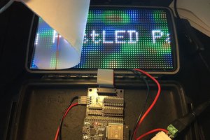
 Louis Beaudoin
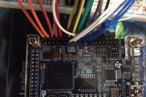
 tehaxor69
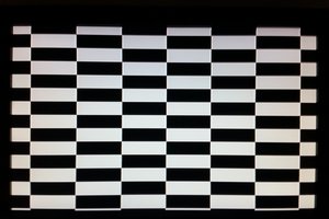
Very interesting. I'm not well-versed in this, but I would like to learn more. Recently, we collaborated with an advertising company that ordered services for configuring a digitale receptie at https://www.2orange.nl/av-ict-expertises/smart-building/digitale-receptie/ for hardware setup and software installation. It was also very intriguing, so this experience has motivated me to deepen my knowledge in the field of digital technologies and information management.