sherwin-dc
Introduction
As part of a larger college group project, I had to program an ESP32 to be a control center for an autonomous rover. The ESP32 was meant to take input from an FPGA that processed images from a mounted camera, make movement decisions and also wirelessly communicate with a remote web server. However, I wanted to go one step further and stream video from the FPGA camera to the web server, through the ESP32.
Although both the ESP32 and FPGA has support for UART, SPI and I2C, I decided to try sending video images using the Inter-IC Sound (I2S) protocol instead. I had found a few projects here on Hackaday that specifically used I2S on the ESP32 to output video or drive a display, but could not find anything online about inputting video with I2S. (The link also has a good explanation of how I2S works)
Of course, the ESP32 comes with a camera driver that uses I2S under the hood, but only a few specific camera modules are supported, with no documentation on how it functions. Furthermore, this requires many pins on the ESP32 (8 pins for pixel data + HSync and VSync + XCLK + pixel CLK = 12 pins excluding camera IO pins).
Fortunately, I was able to use just 5 pins by converting video signals into I2S signals. The basic idea is that I2S was designed to transmit words of data bit by bit, thus only 1 pin is used for data. The other signals are:
- I2S bit clock, SCK
- I2S word select clock, WS
- Clear-To-Send pin to signal to the FPGA that the ESP32 is ready to receive another video frame
- Master Clock, MCK, driven by the ESP32
Setting Up I2S

I2S has both a bit clock (SCK) and a word select clock (WS). I2S was originally designed for transferring digitally-sampled sound signals, with each sample having a certain word length (eg 8, 16, 24 or 32-bits) and no of channels (ie mono or stereo). Hence given the sampling frequency of the sound (fs), the bit clock rate would be calculated as:
ESP32
The ESP32 driver can use I2S in both 'Master' and 'Slave' mode. However, the 'Slave' mode appears to have some problems working with an external SCK signal. Hence we need to utilize the ESP32s own oscillator to provide the clock signal, and feed it back through the FPGA (though this was only done later on). A master clock frequency (MCK) can be set that's driven by an internal oscillator, and outputted on GPIO 0, 1 or 3. Note that MCK needs to be an integer multiple of SCK, and fs is automatically readjusted to accommodate this.
MCK was set to 20 MHz, aiming to be 8 times that of SCK at 2.5 MHz. Using the equation above, this is equivalent to stereo 24-bit sound being transmitted that is sampled at 52 kHz. Faster SCK speeds were not used, though we know that on the ESP8266 it can go as high as 80 MHz.
FPGA
On the FPGA used, video is streamed as a clocked series of pixels, along with hsync and vsync signals. This would normally be connected to the VGA pins and outputted as individual Red, Green and Blue voltages to drive a display. However, with a bit of Verilog code these pixels can be clocked out bit by bit - essentially an I2S signal - along with WS and SCK which can be generated by the FPGA using the MCK signal outputted by the ESP32.
Additionally, during horizontal or vertical blanking, SCK is simply shut off. Hence only pixels that form the image would be read by the ESP32. This is another advantage of using I2S - the data stream can just be 'paused' abruptly to block undesired data and then resumed. This makes it easier to create an image file from the data. The ESP32 additionally asserts a Clear-To-Send (CTS) signal on another pin when it is ready to start reading a new frame, and the FPGA would unblock SCK when a new frame starts.
Ultimately, QVGA resolution (320 x 240) images with 8 bits per pixel were used. This meant each frame uses just 77 kB of precious ESP32 RAM. With SCK at 2.5 MHz, and assuming no blanking periods, each frame would take 0.245s to be read, meaning 4 FPS. If we were to calculate using the theoretical 80 MHz for SCK, we would arrive at 130 FPS (again without blanking). Of course being able to push out frames that fast to an SD card or through WiFi is a different matter altogether. In practice the frame rate was extremely slow as the ESP32 had to wait for other tasks to complete and dedicated streaming protocols were not used.
First Attempt
Initially I wanted to try sending video in 4-bit RGB color, meaning each pixel would be 12 bits long. I selected a word length of 24-bits and dual channel mode in the I2S driver, meaning on each WS cycle 4 pixels would be sent.
After setting the FPGA to generate a completely white reference image, I got the following image from the ESP32. (A portion of the image read was plotted in Python)
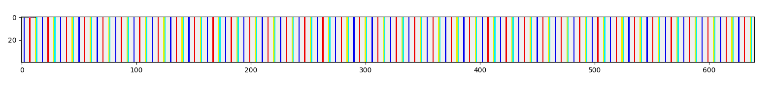
After a bit of digging, I found out that when reading 24-bit words with I2S, padding bytes are inserted after each I2S word, likely to allow the I2S words to be 32-bit aligned. This padding byte inserted at regular intervals had caused the color pattern seen above. Hence I modified the Verilog design to pack four 12-bit pixels into three 16-bit I2S words.
Second Attempt
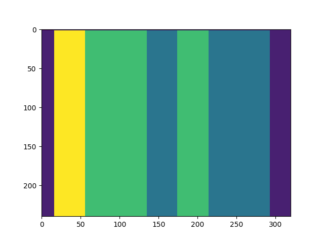
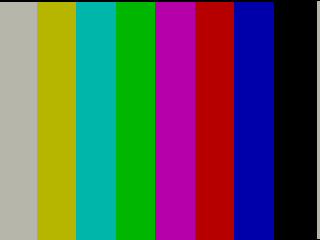
After making the changes, a blank white image could correctly be transmitted and displayed. At this point I changed the reference image produced by the FPGA to a color bar pattern. Note that this consists of all 8 combinations of [Low, High] values of Red, Green and Blue:
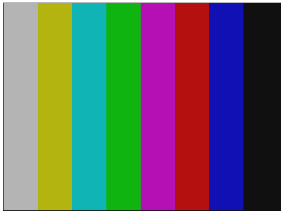
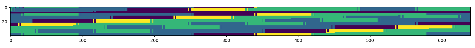
This resulted in this image being transmitted:

The black and grey bars, which have same R,B and G values, can be clearly seen while the other colors cannot. This was because the ESP32 has a little-endian CPU, and hence every group of 4 bytes is reordered when storing 32-bit words to memory. This reshuffled the RGB values packed across multiple bytes, resulting in the pattern. This effect is more apparent after switching to transmitting 8-bit monochrome images instead (monochrome intensities visualized):
The byte ordering was fixed by simply reversing the ordering of each sequence of 4 pixels within the FPGA, which was much easier now that 8-bit pixels were being used.
Up till this point, the SCK signal fed into the ESP32 was derived from the FPGA clock instead of MCK from the ESP32. Hence SCK was slightly out of sync causing pixels to be dropped and the images to be diagonalized. This was rectified after feeding MCK from the ESP32 to the FPGA and using that to get WS and SCK.
Third Attempt
Although at this stage monochrome images could be successfully transmitted, I wanted to still try and use color images. Additionally, converting the data read into an image format would make it easier for the image to be displayed by any program.
Hence I decided to use 3-3-2-bit RGB to still preserve 8-bit pixels while using color. Since the data read into memory by the I2S driver already contains the whole image as a sequence of pixels, it was easiest to use the bitmap image format (BMP). This simply meant adding a header before the image containing the image dimensions, orientation and including a color palette for the 3-3-2-bit RGB values. However at the start of each frame there was always a small number of blank pixels read before the frame started, causing the image to be horizontally misaligned.
Sadly, not all modern programs are able to display the image correctly. VScode and Chrome, for example, only displays 3 out of the 8 colored bars, and even then with incorrect colors. Though the images display correctly in most native Windows programs such as IE, Paint and the Photo Viewer. This meant that images had to be resaved as a modern 32-bit BMP, before being displayed on the webpage as a series of images to form a video stream.
Finally, it was time to connect the camera and view the result. Unfortunately, sending the images over TCP to be displayed was not as smooth and the video feed would commonly freeze. The video stream was at best 0.5 FPS, if being optimistic. The following GIF is a clip of the video streamed, sped up 5x. The video resolution and 8-bit color was at least sufficient enough to distinguish between different colors and make out background details.