 Leonard Pollak
Why I made it
When building microcontroller projects I often found myself cobbling together an RTC, a charger and some sort of regulator often in the form of breakout boards.
Most of the time you end up with a working, albeit not-so-pretty but colorful salad of wires.
While browsing charging ICs from various manufacturers i stumbled upon the ADP5360. It is marketed as an "Advanced Battery Management PMIC" which it totally is. There is none quite like it, but what intimidated me was that it is only available as an 0.4mm pitch WLCSP (Wafer-level Chip Scale Package).
Last year I dumped a bunch of money on this project taking advantage of the assembly service many PCB manufacturers offer. I would consider it a great learning experience but I wasn't quite satisfied with the result.
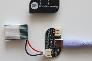
So this year I decided to have a new take on the old project and cram what I consider the most essential components onto a small PCB module with castellated edges so I could use it for prototyping as well as as solder-on module for "finished" projects.
As far as I know this is the first module using the ADP5360. Combined with the extremely accurate MAX31343 RTC and a level shifter it is a lot of premium components on a very small module that can enable anyone to make low-power battery powered devices.
Features Overview
What follows is a list of this boards features that should give you a broad idea of the module's capabilities. If you want to know more about the details consider reading the linked datasheets.
Buck/Buck-Boost
- Buck: 0.6-3.75V (1.8V default) current limit: 100-400mA
- Buck-Boost: 1.8-5.5V (3.3V default) current limit: 100-800mA
- 1.1A max drain current from battery
Li-Po Charger
- Battery protection
- NTC temperature sensor (optional)
- Compliant with JEITA charge temperature specification
- Battery fuel gauge (battery capacity adjustment with aging/temperature)
RTC
- High accuracy (±5ppm)
- Two time-of-day alarms
- Supercapacitor backup
I2C level shifter
- Converts I2C clock and data lines between configured levels
- Integrated 10 kOhm pull-up resistors
- Enable/Disable pin (power saving)
Other features
- Small footprint: 2x2 cm (0.8x0.8 in)
- Castellated edges -> breadboard and PCB friendly
- "Shipment mode"
 Ultimate Robotics
 Ampeater
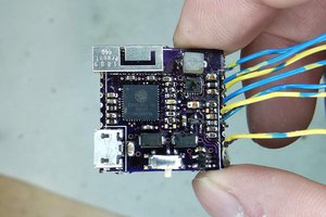
 Jarrett
 Michel Kuenemann