 Mario Ninic
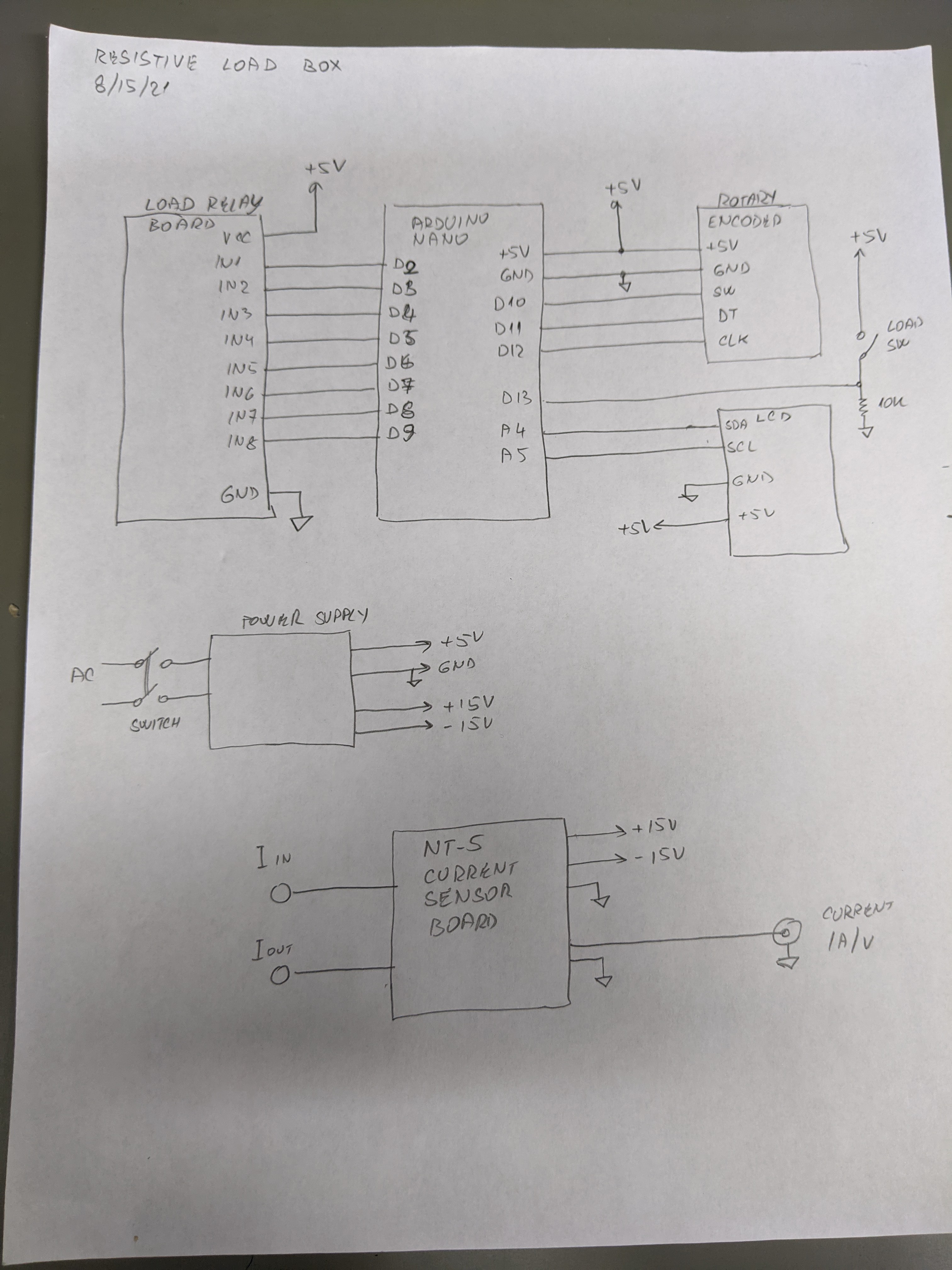
Resistive load box system diagram:
Load Resistors connections.
All resistors are mounted on the large heatsink. All connections from the NC to Com terminals are soldered to minimize resistance and terminal connections issues, not perfect but good enough.
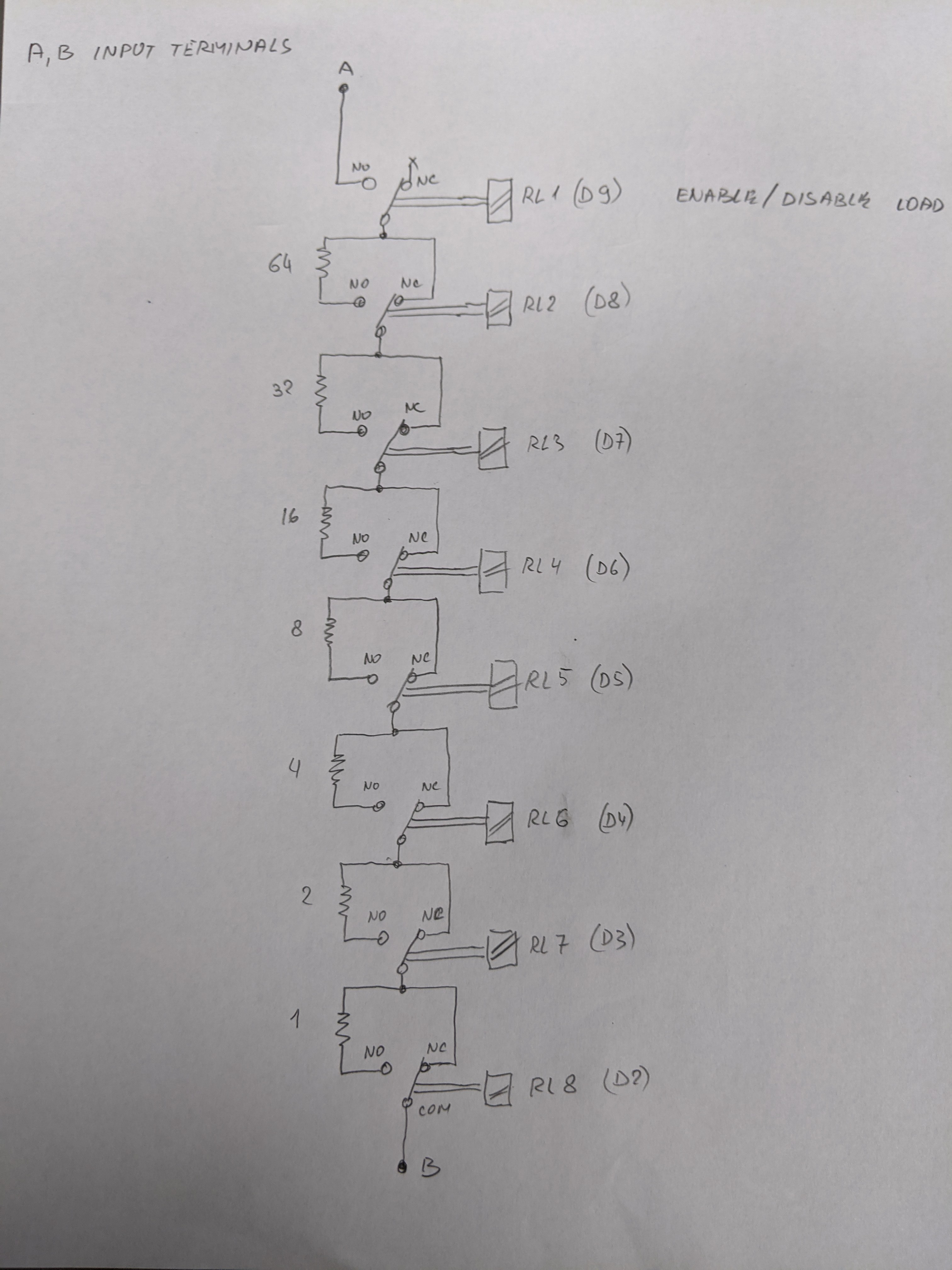
The terminals A and B are input terminals for the load box. The load side is insulated from the control circuitry.
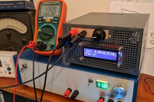
When using load box, care must be taken not to excide resistor rated power dissipation. For example:
When testing 12V battery or power supply, the minimum selected resistance should be 3 Ohm (for the short period of time).
Future upgrade:
Add computer control.
Add thermal sensor to monitor and display resistor temperature and to control cooling fan.
Add insulated voltage and/or current monitor to control power dissipation on the resistors.

 Tim Savage
 MagicWolfi
 Bharbour
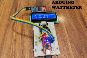
 Lithium ION
If somebody wants to update code to make serial port control please let me know and I will make LabView user interface.