Rationale
Thermal imaging is a very useful tool for applications as diverse as home renovations (e.g for checking home insulation or for monitoring wear and tear on power tools) automotive repair and maintenance, or electronics. Being able to see, at a glance, the relative temperatures of different objects can make a range of design and diagnostic tasks much faster.
While the price of imaging sensors in the visible-light spectrum has plummeted in recent decades, long-wave infrared imaging remains a relatively expensive niche market. Commercial off-the-shelf (COTS) solutions exist, but are relatively expensive. Prices for a ready-to-use thermal camera begin at around USD500 and only go up from there. This places them out of reach of the casual hobbyist, student, or DIYer.
Due
to the COVID19 pandemic in 2020-21, all thermal imaging tools and
components have become scarce. A quick search of online electronics
suppliers (Digikey, element14) shows that ~80% of all thermal imaging
equipment is unavailable as of June 2021. As of June 2021, there is
also an ongoing chip shortage which has affected availability of
many of the supporting electronics components, from microcontrollers
(MCUs) to passives like capacitors: https://amp.theguardian.com/technology/2021/may/14/global-shortage-of-computer-chips-could-last-two-years-says-ibm-boss
Presented here is a homemade device that can use the MLX90640 thermal sensor from Melexis. This sensor is available from Digikey, who can also supply a selection of breakout boards from Adafruit and Sparkfun.
This
project builds on previous work published by Adafruit* for use with
their MLX90640 breakout. The design presented here should be
compatible with a wider range of 32-bit Arduino development boards
and sensor packages. This should help the reader avoid some of the
aforementioned supply chain issues. * https://learn.adafruit.com/mlx90640-thermal-image-recording
The design presented here has been assembled for under USD150, a significant saving compared to a COTS option. It also has the advantage that it can be customised to your needs, or to suit local availability of components.
Disclaimer
During the COVID19 pandemic, some parties have attempted to use thermal imaging as a diagnostic tool to identify people infected with COVID19, in a similar way as thermal imaging was used to identify SARS-positive patients during that earlier epidemic. Thermal imaging is NOT effective for COVID19, for a range of reasons.
- There is often a delay between being infected (and infectious) and showing symptoms.
- Not all patients ever develop a fever.
- Using skin temperature to diagnose fever is unreliable for any disease, not just COVID19.
- The MLX90640 sensor is NOT rated for medical use, and does not have the resolution or accuracy required for diagnosing fever temperatures in humans.
It may be tempting to use a tool like this to try and help out with the pandemic response, or to get funding for your work, or just to try and get more attention or views for your project online. Please don’t do this.
Design
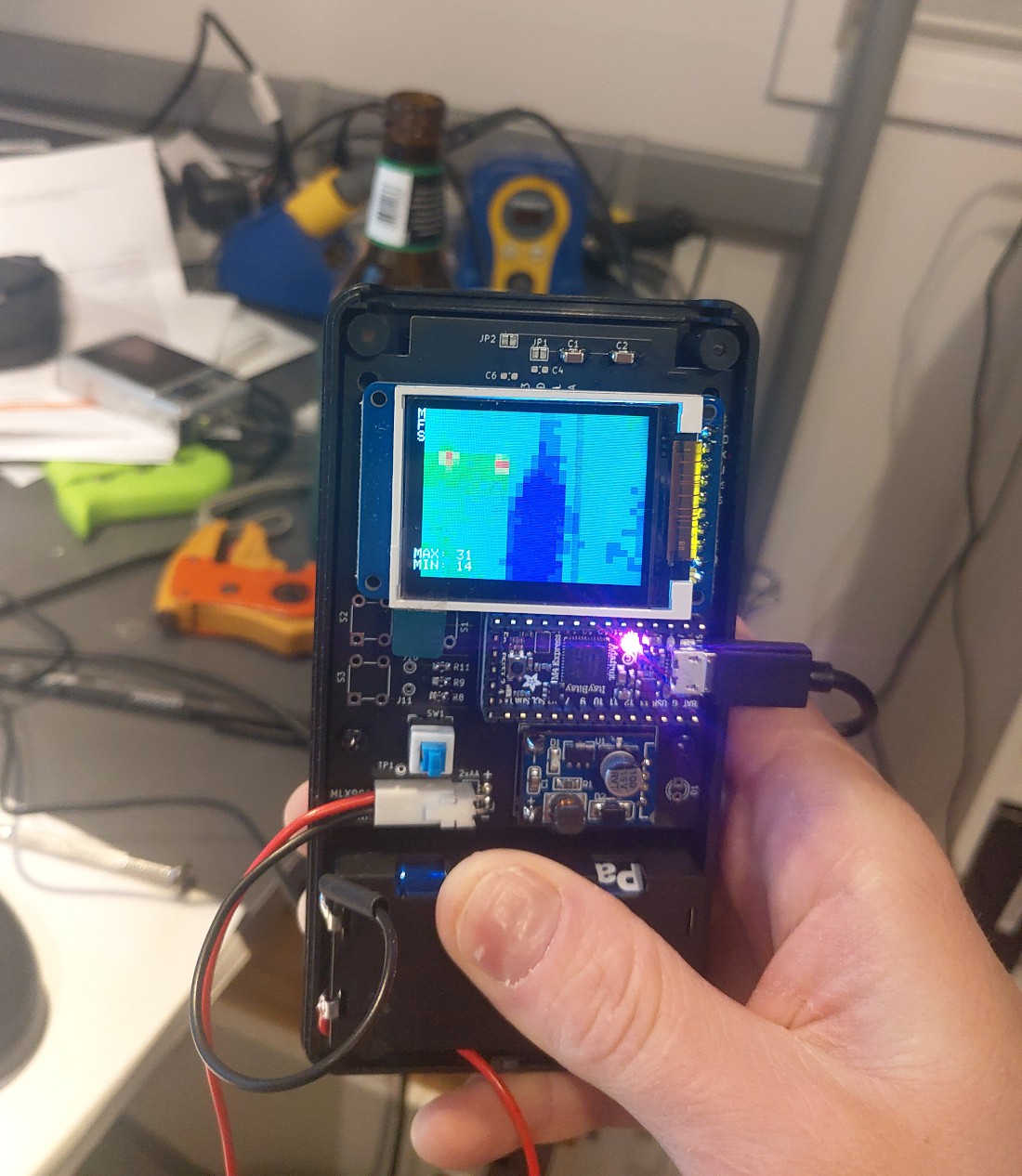
The
Melexis MLX90640 sensor is an array of 32 x24 thermopiles that are
sensitive to thermal radiation. This is usually radiation in the wavelengths of 8-14µm (but I couldn't find the specifics in the datasheet - let me know if you find this info for the MLX90640!) This is a lower resolution than a commercial
thermal camera, but good enough for hobbyist work. It communicates
with the MCU via the I2C bus. Melexis have excellent documentation
for both the sensor and its communication protocol. Sparkfun has
published some suggestions for simulating higher resolution with
software interpolation but this design uses the native resolution of
the sensor. https://learn.sparkfun.com/tutorials/qwiic-ir-array-mlx90640-hookup-guide
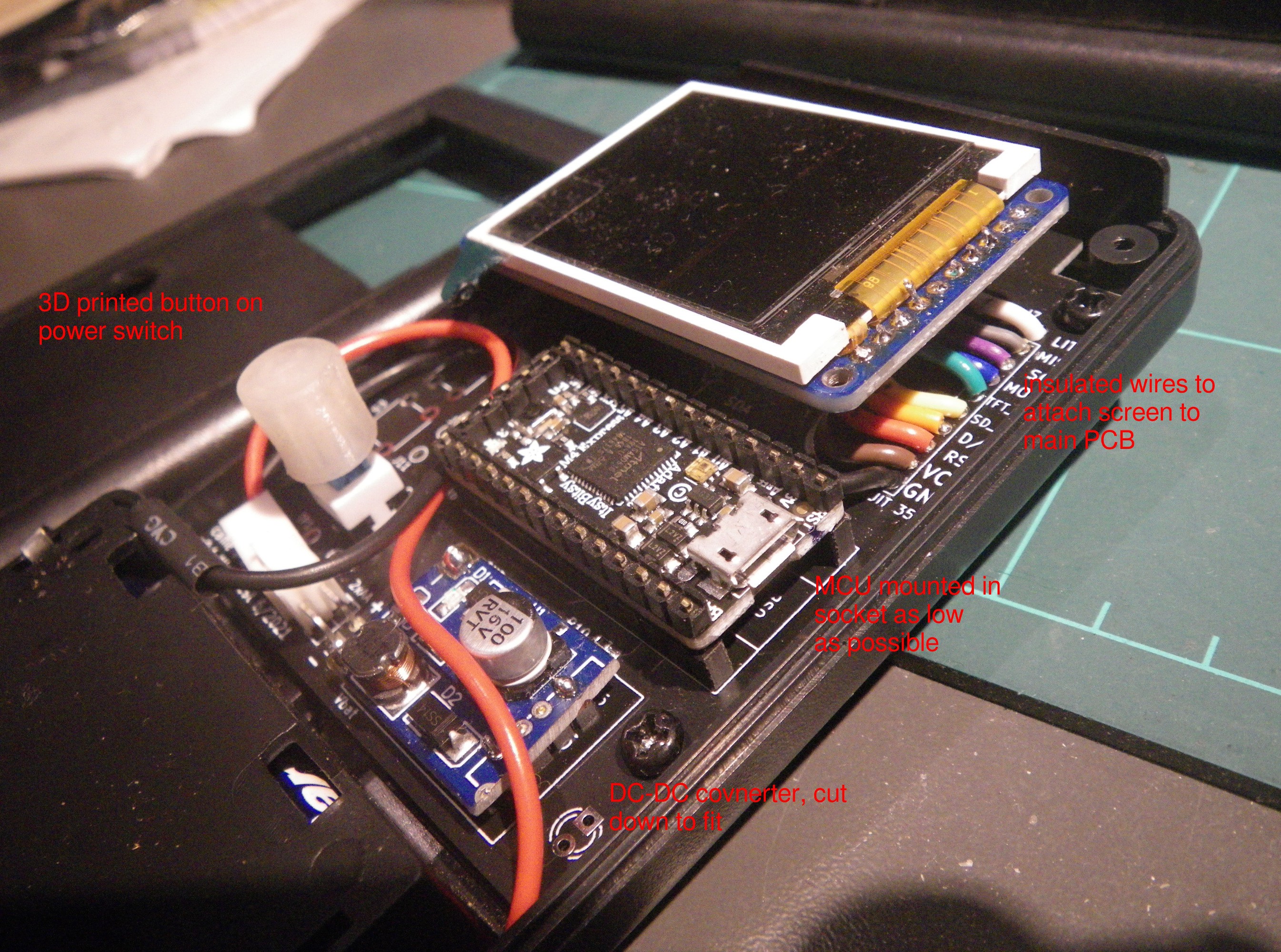
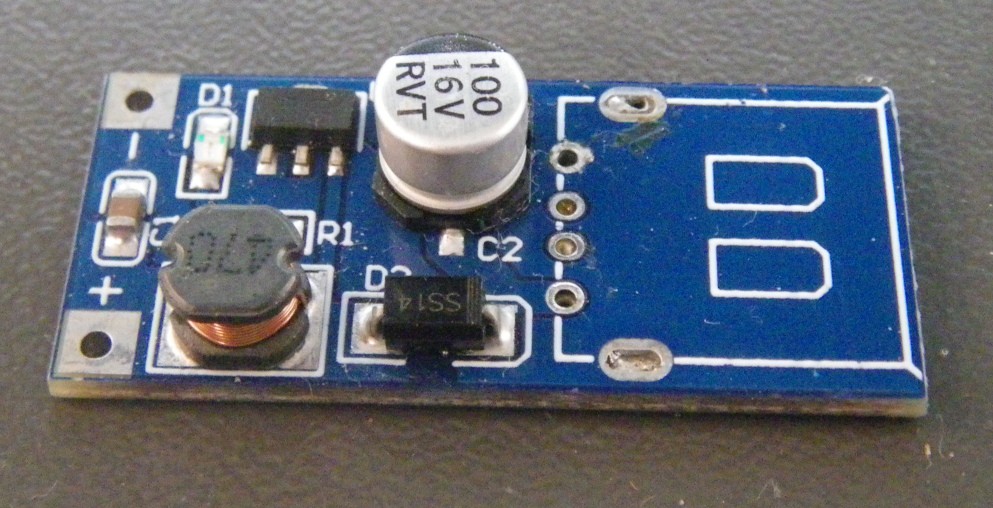
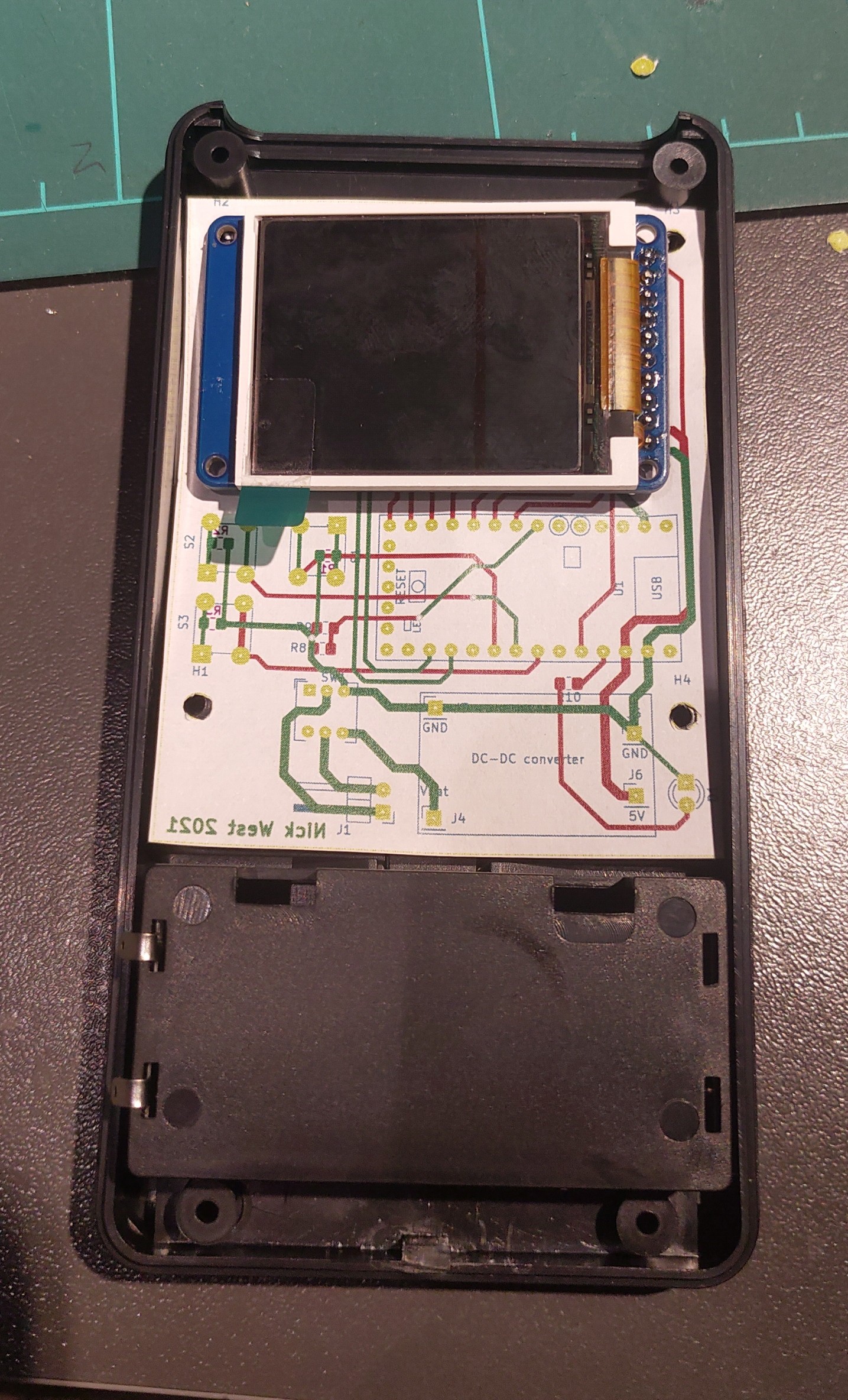
The carrier PCB is the heart of the physical design. This PCB was designed to suit any of 4 different breakout boards for the MLX90640 sensor, and could also...
Read more »


 deʃhipu
 Stephen Harrison
 C. Scott Ananian