 David H Haffner Sr
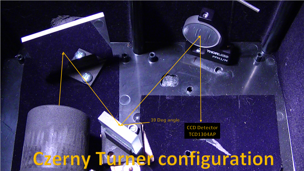
I am never too proud to admit when I have "hit" the proverbial brick wall of discovery, I have, with the concept of using the JDEPC-05 cmos camera as the detector for this project. The cmos chip will not work with this configuration, I understand now why, (duh...) I should have known this from the start a year ago, as soon as I got the diffraction grating and second mirror aligned, it was like magic, a very nice, visable spectral line.
The problem was, it was approx. 50mm wide. That's when I realized my error, "spectral dispersion", the reason the DVD or holographic sheet works with the cmos type camera is because of incident light dispersion. The spectral "beam" does not "fit" correctly with the incident angle of the cmos camera lens, and consequently, the cmos camera will not work without the lens focusing the light image!
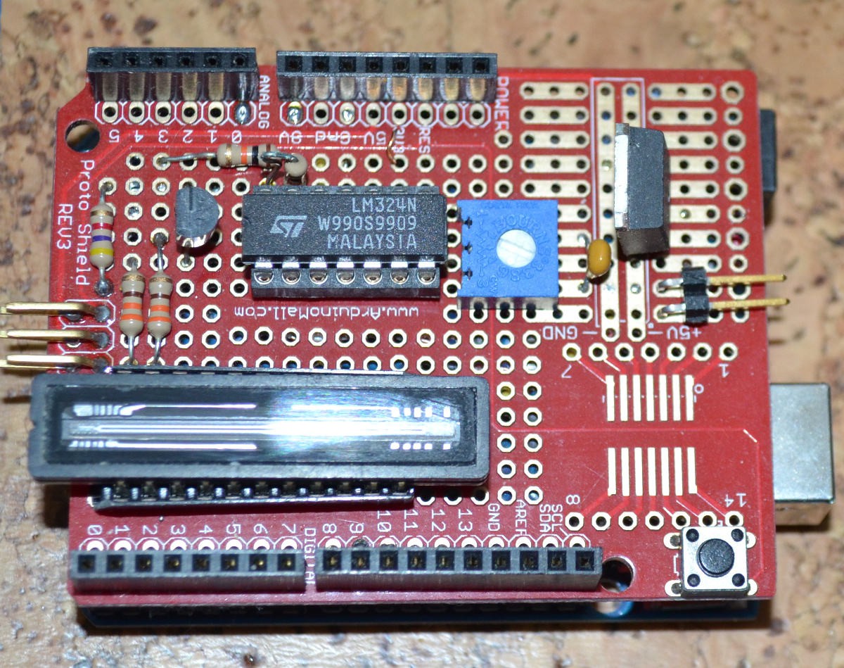
So...I am making a hybrid of http://hackaday.io/project/9829-linear-ccd-module, the one esben rossel made, I'll be using an Arduino R3 as the micro processor to run the TCD1304 linear CCD chip.
I am posting the schematics for the circuit design and protoboard pics (which are from David Allmon, http://davidallmon.com/pages/ccd-transmission-spectrograph) this is the 10 bit version of the controller, there is a 16 bit version which is available, but I want to build this one first and test it out before delving into the 16 bit controller.
Also I am posting the micro controller software code;
 *note, disregard the lamp part of the schematic as it is not required, only the controller is.
 #include <util/delay_basic.h>
#ifdef ARDUINO_AVR_MEGA2560
#define LAMP 0x20
#define SH 0x40
#define ICG 0x80
#define MCLK 0x10
#else
#define LAMP 0x01
#define SH 0x02
#define ICG 0x04
#define MCLK 0x08
#endif
#define CLOCK PORTB
uint8_t buffer[800];
uint8_t avg = 0;
char cmdBuffer[16];
int cmdIndex;
int exposureTime = 20;
void setup()
{
uint8_t val;
// Initialize the clocks.
DDRB |= (LAMP | SH | ICG | MCLK); // Set the clock lines to outputs
CLOCK |= ICG; // Set the integration clear gate high.
// Enable the serial port.
Serial.begin(115200);
// Setup timer2 to generate a 470kHz frequency on D11
TCCR2A = + (0 << COM2A1) | (1 << COM2A0) | (1 << WGM21) | (0 << WGM20);
TCCR2B = (0 << WGM22) | (1 << CS20);
OCR2A = 20;
TCNT2 = 1;
// Set the ADC clock to sysclk/32
ADCSRA &= ~((1 << ADPS2) | (1 << ADPS1) | (1 << ADPS0));
ADCSRA |= (1 << ADPS2) | (1 << ADPS0);
}
void readCCD(void)
{
int x;
uint8_t result;
CLOCK &= ~ICG;
_delay_loop_1(12);
CLOCK |= SH;
delayMicroseconds(5);
CLOCK &= ~SH;
delayMicroseconds(15);
CLOCK |= ICG;
delayMicroseconds(1);
for (x = 0; x < 800; x++)
{
CLOCK |= SH;
if (x == 0)
{
avg = (uint8_t)(analogRead(A0) >> 2);
result = (uint8_t)(analogRead(A0) >> 2);
}
else
{
result = (uint8_t)(analogRead(A0) >> 2);
if (result < avg)
{
result = 0;
}
else
{
result -= avg;
}
buffer[x] = result;
delayMicroseconds(20);
}
CLOCK &= ~SH;
}
}
uint16_t centroid()
{
uint16_t x;
uint32_t sum = 0;
uint32_t so_far = 0;
uint32_t half_max;
for (x = 0; x < sizeof(buffer); ++x)
{
sum += buffer[x];
}
half_max = sum / 2;
for (x = 0; x < sizeof(buffer); ++x)
{
so_far += buffer[x];
if (so_far >= half_max)
{
return x;
}
}
}
void sendData(void)
{
int x;
for (x = 0; x < 800; ++x)
{
Serial.println(buffer[x]);
}
}
void loop()
{
int x;
if (Serial.available())
{
cmdBuffer[cmdIndex++] = Serial.read();
}
if (cmdBuffer[0] == 'r')
{
sendData();
}
else if (cmdBuffer[0] == 'l')
{
CLOCK &= ~LAMP;
}
else if (cmdBuffer[0] == 'L')
{
CLOCK |= LAMP;
}
else if (cmdBuffer[0] == 'e')
{
if (--exposureTime < 0) exposureTime = 0;
Serial.print("Exposure time ");
Serial.println(exposureTime);
}
else if (cmdBuffer[0] == 'E')
{
if (++exposureTime > 200) exposureTime = 200;
Serial.print("Exposure time ");
Serial.println(exposureTime);
}
else if (cmdBuffer[0] == 'c')
{
Serial.print("Centroid position: ");
Serial.println(centroid());
}
cmdBuffer[0] = '\0';
cmdIndex = 0;
readCCD();
delay(exposureTime);
}

Discussions
Become a Hackaday.io Member
Create an account to leave a comment. Already have an account? Log In.
how can i run this code in ardunio due board
Are you sure? yes | no
Thanks for the post. I am trying to replicate the circuit but I am not sure what the potentiometer (R6) is for. Can you elaborate on it and explain how to adjust it?
Are you sure? yes | no
Hi David,
Thank you for posting your project. I found that if I modified your code to speed up the ADC routine, I could get the Uno to aquire a reading at 8 msec, which was enough to get much better resolution. I could get a reading for all 3648 pixels on the Uno (although I had to interlace the readings over several runs). Since I went with staggering my measurements, I was able to speed up the clock to 1 MHz, which makes the chip run much happier. The big problem was fitting them in memory, so I recruited the 23LC1024 SRAM chip. I also didn't bother with the shutter mode for my project, as you did in the code you posted, because I needed the sensitivity. A few warm-up runs were needed in my function call, since I didn't let acquisition happen continuously as you did. Bottom line, the Uno (with a little help) CAN handle the TCD1304. So here is my code, in case it helps anyone. I'm happy to report it compiles with lots of room to spare! It calls a library I wrote for the 23LC1024, available here: https://github.com/dndubins/SRAMsimple
/* Original sketch available at:
* https://hackaday.io/project/18126-dav5-v301-raman-spectrometer/log/53099-using-an-arduino-r3-to-power-the-tcd1304ap-ccd-chip
*
* 23LC1024 - Uno:
* ---------------
* Pin1 (JSC) -- Pin 10 (CS) (with 10K pullup to +5V)
* Pin2 (SO) -- Pin 12 (MISO)
* Pin3 (NU) -- 10K -- +5V
* Pin4 (GND) -- GND
* Pin5 (SI) -- Pin 11 (MOSI)
* Pin6 (SCK) -- Pin 13 (SCK)
* Pin7 (HOLD) -- 10K -- +5V
* Pin8 (V+) -- +5V
*
* TCD1304 - Arduino Uno R3
* ------------------------
* pin 3 (ICG) - D5
* pin 4 (MCLK) - D3
* pin 5 (SH)- D6
*/
#include <SRAMsimple.h>
#define CSPIN 10 // Default Chip Select Line for Uno (change as needed)
SRAMsimple sram; //initialize an instance of this class
//#define MENUMODE // comment out for continuous readings
#define PIXELS 3648 // default: 800 (3648 max). Use 800 for the Uno.
char cmdBuffer[16];
int cmdIndex;
int exposureTime = 20; // play with this for a good exposure time
#define CLOCK PORTD // use PORTD for the UNO (make room for MOSI, MISO, and SCK for the 23LC1024)
#include <util/delay_basic.h>
#define ICG (1<<5) // PD5 (Digital Pin 5)
#define MCLK (1<<3) // PD3 (Digital Pin 3)
#define SH (1<<6) // PD6 (Digital Pin 6)
// needed to switch to adc-fast mode later
#ifndef cbi
#define cbi(sfr, bit) (_SFR_BYTE(sfr) &= ~_BV(bit))
#endif
#ifndef sbi
#define sbi(sfr, bit) (_SFR_BYTE(sfr) |= _BV(bit))
#endif
void setup(){
SPI.begin(); // start communicating with the memory chip
byte val;
// Initialize the clocks.
DDRD |= (SH | ICG | MCLK); // Set the clock lines to output mode
CLOCK |= ICG; // Set the integration clear gate high.
// Enable the serial port.
Serial.begin(115200);
#ifdef MENUMODE
Serial.println("Program start.");
Serial.println("Serial Monitor Commands:");
Serial.println("r: read diode array");
Serial.println("e: decrease exposure time");
Serial.println("E: increase exposure time");
Serial.println("Enter choice:");
#endif
// Setup timer2 to generate a 1 MHz frequency on PD3 (Pin3) using FastPWM mode (affects pins 3 and 11)
//Just Pin 3:
pinMode(3, OUTPUT); // output pin for OCR2B, this is Arduino pin number
TCCR2A = _BV(COM2A1) | _BV(COM2B1) | _BV(WGM21) | _BV(WGM20); // inverting mode, fast PWM
TCCR2B = _BV(WGM22) | _BV(CS20); // no prescaling
OCR2A = 15; // counter limit: 255
OCR2B = 7; //duty cycle, can't be greater than OCR2A. (OCR2B=0.5*OCR2A for 50% duty cycle)
//duty cycle =OCR2B/OCR2A
// faster ADC modes: http://yaab-arduino.blogspot.com/2015/02/fast-sampling-from-analog-input.html
cbi(ADCSRA,ADPS2); // sbi is HIGH, cbi is LOW
sbi(ADCSRA,ADPS1);
sbi(ADCSRA,ADPS0);
// 0 0 1 --> prescaler=2 --> 8 usec per analog reading
// 0 1 0 --> prescaler=4 --> 8 usec
// 0 1 1 --> prescaler=8 --> 12 usec <-- provided best experimental results
// 1 0 0 --> prescaler=16 --> 20 usec
// 1 0 1 --> prescaler=32 --> 32 usec
// 1 1 0 --> prescaler=64 --> 60 usec
// 1 1 1 --> prescaler=128 ---> 116 usec
}
void readCCD(unsigned int pixels, int expos){
byte warmUps=20; // number of readings to adjust to new exposure time (set to >10)
for(uint32_t x=0;x<pixels;x++){
sram.WriteUnsignedInt(2*x,0); // initialize buffer
}
unsigned int timer1=millis();
for(int y=0;y<20;y++){ // warmup runs
CLOCK &= ~ICG; // set ICG low
delayMicroseconds(1); // timing requirement (1000 ns max)
CLOCK |= SH; // set SH high
delayMicroseconds(1); // timing requirement (1000 ns max)
CLOCK &= ~SH; // set SH low
delayMicroseconds(5); // timing requirement (min 1000ns, typ 5000 ns)
CLOCK |= ICG; // set ICG high
_delay_loop_1(1); // wait a tick (supposed to be t4 in the datasheet, 20 ns)
delayMicroseconds(14780); // delay an entire cycle
delay(expos);
}
for(int y=0;y<24;y++){
CLOCK &= ~ICG; // set ICG low
delayMicroseconds(1); // timing requirement (1000 ns max)
CLOCK |= SH; // set SH high
delayMicroseconds(1); // timing requirement (1000 ns max)
CLOCK &= ~SH; // set SH low
delayMicroseconds(5); // timing requirement (min 1000ns, typ 5000 ns)
CLOCK |= ICG; // set ICG high
_delay_loop_1(1); // wait a tick (supposed to be t4 in the datasheet, 20 ns)
delayMicroseconds(128+(4*y)); // delay until the correct first pixel
//unsigned int timer1,timer2;
for(int i=y;i<pixels;i+=24){ // should amount to 152 pixel readings
//timer1=micros();
sram.WriteUnsignedInt(i*2,analogRead(A0)); // takes about 64 usec
//timer2=micros();
//Serial.println(timer2-timer1);
delayMicroseconds(40); // delay between readings
}
delayMicroseconds(4*(24-y)+52); // skip the last pixels plus trailing dummy outputs
delay(expos);
}
}
void sendData(void){ // Sends diode array data to serial monitor
for (uint32_t x=0;x<PIXELS;x++){
if(x>0){Serial.print(",");} // for CSV format
Serial.print(sram.ReadUnsignedInt(2*x));
}
Serial.println();
}
void loop(){
#ifdef MENUMODE
// Begin serial commands
if (Serial.available()){ // Listening for serial monitor commands
cmdBuffer[cmdIndex++] = Serial.read();
}
if (cmdBuffer[0] == 'r'){ // read the CCD (and send data to the serial monitor)
readCCD(PIXELS,exposureTime);
sendData();
Serial.println("Enter choice:");
}
else if (cmdBuffer[0] == 'e'){
if (--exposureTime < 0) exposureTime = 0;
Serial.print("Exposure time ");
Serial.println(exposureTime);
}
else if (cmdBuffer[0] == 'E'){
if (++exposureTime > 200) exposureTime = 200;
Serial.print("Exposure time ");
Serial.println(exposureTime);
}
cmdBuffer[0] = '\0'; // erase the command buffer
cmdIndex = 0;
#endif // end of MENUMODE serial commands
#ifndef MENUMODE
readCCD(PIXELS,exposureTime);
sendData();
//delay(1000); // optional delay for continuous reading
#endif
}
Are you sure? yes | no
Hi David,
I am trying to make my own spectrometer project and guided by your code and circuit you used.
Since I am a beginner in Arduino I have huge time problems regarding driving and collecting data from TCD1304. When I upload program to Arduino Mega 2560 nothing seems to happen on Serial Monitor or Plotter. My programming skills are poor but if you could give me some guidelines it would be extremely appreciated and helpful.
Are you sure? yes | no
Hi Dave,
beginner as I am, I'm trying to compile this code on your page and am trying to use arduino ide. However it does not like this line: #include <util/delay_basic.h> or the def statements.
So I thought to try avr studio (v5.1) and things seem to get down the track of compiling a bit better , but when i come to the line: Serial.begin(115200); I get:
Error 1 'Serial' undeclared (first use in this function) C:\Users\david000\Documents\AVRStudio 5.1\AVRGCC1_dav\AVRGCC1_dav\AVRGCC1_dav.c 44 2 AVRGCC1_dav
It seems I should add a header file here, but I don't know what . Afterall its not in your example. in fact Serial.begin() seems to be from the Arduino IDE. So I'm confused as to what to use to build your example.
Any help would be appreciated (but probably not deserved.)
dazza000
Are you sure? yes | no
Hey K.C lee, thanks for doing the sim, very helpful. This is what I will be using to drive the chip; The Mega 2560 is a microcontroller board based on the ATmega2560. It has 54 digital input/output pins (of which 15 can be used as PWM outputs), 16 analog inputs, 4 UARTs (hardware serial ports), a 16 MHz crystal oscillator, a USB connection, a power jack, an ICSP header, and a reset button. It contains everything needed to support the microcontroller; simply connect it to a computer with a USB cable or power it with a AC-to-DC adapter or battery to get started. The Mega 2560 board is compatible with most shields designed for the Uno and the former boards Duemilanove or Diecimila.
I'm pretty sure that this latest Arduino micro controller has the power to drive this chip at the specs I need.
Are you sure? yes | no
The Atmega has the same CPU core speed and sampling rate for its 10-bit ADC. It all depending on what you are expecting out of it.
If you ever need high processing power and higher ADC sampling rate, ARM chips are the logical next step.
Are you sure? yes | no
Thanks K.C.Lee, I really appreciate all your help, it does make sense to use the ARM chip, I just want to make sure this is going to work first, before investing time and resources into a more expensive and elaborate system.
The detector needs to be inside the enclosure, the processor will have to be in a separate enclosure outside the main body, the whole premise of this project was to have a portable and durable high end spectrometer.
I'm just going to have to adapt this project to this "system" upgrade :)
I'm going to use your suggested op amp, at digikey, (MCP6002) it'll work perfect.
Thanks again for your help :)
Are you sure? yes | no
Hello esben, you said; "Also, can you elaborate on the temperature problem of the different sides of the TCD1304, because that is something I have not noticed?"
I was talking about thermal noise, that's caused by random thermal electron-hole pairs.
I would have used your design to a tee, but whether it was Raspberry Pi or UART, its all Linux based, I use windows 10, there would have been too much tweaking and still no guarantee of a successful transition. The Arduino R3 solves this problem for me. Plus it is easier to write a script that makes it compatible with Spekwin32's live capture control program, (all Windows based.)
Are you sure? yes | no
Might want to consider a rail to rail output opamp as the LM324 is limited to 0-3.5V output range for 5V supply. i.e. you are throwing out 30% of the ADC resolution. Or you could raise the supply to the opamp...
Are you sure? yes | no
Hey K.C Lee, I am really glad that you and Ted commented on this venture, I haven't built anything like this since 2000, so I am "really" rusty. I noticed on the spec sheet that input is 3v, (min) so I need it @ 5v max, I think it should be ok at 5v?
Are you sure? yes | no
The CCD output is 1.5V to 3.5V, so if you are willing to live with a reduced resolution, the LM324 is fine as is.
To get the most resolution, you want to stretch that voltage range to the 0-5V range of your ADC with your opamp circuit providing some gain.
The LM324 at 5V is not going to work. The LM324 has limited input and output ranges.
Input Common-Mode: 0 to V+ −2 (full range) 0 to V+ -1.5V (25C)
Output range: 0 - V+ -1.5V
One way to get around that is to raise the supply to the LM324 by 1.5V i.e. to at least 6.5V or to shop for a newer opamp with RIO (Rail to Rail Input/Output).
Are you sure? yes | no
Hey K.C, any suggestions for the LM324 replacement?
Resolution is very critical.
Are you sure? yes | no
Microchip - DIP packages and similar specs (1MHz GBW)
MCP6002-I/P for dual opamp
http://www.digikey.com/product-detail/en/microchip-technology/MCP6002-I-P/MCP6002-I-P-ND/500875
MCP6004-I/P for quad opamp
http://www.digikey.com/product-detail/en/microchip-technology/MCP6004-I-P/MCP6004-I-P-ND/523060
You could use a Op-amp differential amplifier
with V2 set to the offset: 1.5V and gain to 2.5X to amplify the 1.5V to 3.5V signal into 0V to 5V
Are you sure? yes | no
I did a quick simulation:
The RIO opamp running at 5V means that the output won't go above 5V, so that's worth considering. The 1.5V would be coming from your trimpot and it will be subtracted from the CCD output.
Green trace is the input from V4, Blue is the opamp output
Are you sure? yes | no
I know nothing about op-amps, so I'm happy to see this discussed. That simulation looks cool, but the time scale should be at least 3 orders of a magnitude faster (the CCD's output comes out at 500 kHz).
Dave Allmon who did all this for his first version, went on to use a AD8021 to condition the signal for his 16-bit spectrograph. Is there any sense in choosing a different op-amp?
And still, I don't see the sense in using his first version. I don't know arduinos and didn't look into the code (even if it's posted here as well), but on his site he specifically writes that it's only fast enough to digitize 800 pixels. Why trace his work from the beginning, when you know you have to upgrade to a faster ADC later on?
Are you sure? yes | no
Your Arduino ADC can't handle that speed nor your code can process that at all.
Atmega 328: ADC Up to 76.9kSPS (Up to 15kSPS at Maximum Resolution)
Might want to look at ARM based one and write some DMA code?
Also you'll need opamp with higher GBW (Gain * Bandwidth) with at least 1.5MHz
AD8021 is a good choice.
Are you sure? yes | no
Yes ARM with ADC+DMA works very well for this application.
With the drive circuit in the datasheet the output is typically in the range 1.5-3V, so I'm filling only half the ADC's range (the STM32F4 series' ADC is 12-bit).
I didn't think about temperature the coefficient of the output transistor as well, but that's an extra incentive to steal Dave Allmon's conditioning circuit.
Are you sure? yes | no
You might want to adjust those values for the "ad7667-spectrograph-schematic-lg.png"
R4 (8.3R), C8 (47nF) vs the ones in AD7667 datasheet figure 26 with R4 (15R), C8 (2.7nF)
The RC values for low pass antialiasing filter are an order of magnitude off. I would expect C8 to be 4.7nF
Using the online calculator: fc = 407984.98613662[Hz] shows the 47nF is actually about right.
I guess I am used to be seeing that range of values.
Are you sure? yes | no
Hi David,
I see that the basic idea for that circuit is taken from the datasheet, including the PNP follower on the output. My guess is that this introduces a temperature dependence that you may not want. From the datasheet, the output of the device seems very flat with temperature (either that, or they forgot to draw a curved line in the figure on page 11):
http://www.spectralproducts.com/pdf/TCD1304.pdf]
I don't know why they would add a simple emitter follower after such a nice temperature-independent output when a cheap op-amp would do much better. Even assuming the whole 5V range is used for 10 bits, that's around a 5mV LSB. The tempco of the Vbe drop of the 2N3906 might be around -2 mV/K at these currents, so you'd lose an LSB of accuracy for every 2.5 degree temperature drift. I suspect (without investigating more closely) that less than the entire 5V range is being used, making the problem worse.
I haven't looked at the 16-bit version you mention, but if the PNP follower is still there, it would cause even more (64x more?) issues.
Of course, I don't know anything about the thermal stability of your setup, or your calibration procedures, or what effects temperature will have on the optics setup, so this may not be a large issue in the whole system, but might be something to consider.
Are you sure? yes | no
Hey Ted, thanks for your reply, I know that you are right in the thick of these things and very knowledgeable, so, I am going to be running it at 5v max, I don't know the reason why the author has it running at 3.3, it may be, because of temp problems, especially towards one end or the other at the photo diode (I noticed this effect from esben's linear CCD design, using the same chip.)
Thermal stability is a "big" issue, I had noticed it with this schematic. I can either cool it down witha fan (which I would rather not,) or perhaps if you have a better suggestion on the LM324 or the 2N3906?
Calibration is easier with a CCD sensor, it works the same as my camera on my microscope, you image the dark current (signal without light,) the a baseline (some call it the sample spectrum (light image, sample image ect,.) and subtract the dark from the reference sample and walla!
More signal than noise, hopefully.
Are you sure? yes | no
I could be wrong, but it seems to me that in both Dave Allmon's circuits, the TCD1304 is running at 5V.
Also, can you elaborate on the temperature problem of the different sides of the TCD1304, because that is something I have not noticed?
Are you sure? yes | no