 David H Haffner Sr
Updated 6/26/17 1:58:PM
I updated the code significantly, I added " lcd.setCursor(12, 2); lcd.print(i--);" to the lines of code that control the motor coils so the current shaft position can be seen on the LCD display,
and incorporated a pin int sensorVal[] = { digitalRead [2][3] };//SW1 pin2 & SW2 pin3
This will illuminat LED's #10(W) and LED #12(bl) to indicate that the switches
on HIGH. These values are then displayed on the LCD menu on line 3 as a monitor
of the switches values.
Note: You can see on the LCD screen that CW & CCW do not change, this is because the speed is way too high and the LCD cannot capture the characters fast enough...I think? Everything works fine when it runs at normal speed.
Here is my code as it stands right now;
#include <LiquidCrystal_I2C.h>
#include <Wire.h>
/* Program 1 REV B
Updated 6/26/2017 @ 1:48:PM
Code concept and project design by David H Haffner Sr.
Stepper program for the 28YBJ-48 (stepper MTR) and ULN2003 driver
This particular stepper motor is 5.625 degrees per step
/64
This is in the public domain.
Compiled size 6196 bytes.
*/
#define yellow 7 // M1
#define orange 5 // M2
#define brown 6 // M3
#define blue 4 // M4
#define CW 2 //Sw1 in schematic
#define CCW 3 //Sw2 in schematic
unsigned long int val = (analogRead('...') / 4 + 10);
LiquidCrystal_I2C lcd(0x3F, 2, 1, 0, 4, 5, 6, 7, 3, POSITIVE); // Set the LCD I2C address
void setup() {
pinMode(10, OUTPUT);// this is the LED pin10
pinMode(12, OUTPUT);// this is for LED pin12
digitalWrite(CW, 1); // pull up on
digitalWrite(CCW, 1); // pull up on
pinMode(blue, OUTPUT);
pinMode(brown, OUTPUT);
pinMode(orange, OUTPUT);
pinMode(yellow, OUTPUT);
// all coils off
digitalWrite(blue, 0);
digitalWrite(brown, 0);
digitalWrite(orange, 0);
digitalWrite(yellow, 0);
lcd.begin(20, 4); // initialize the lcd for 20 chars 4 lines, turn on backlight
// ------- Quick 3 blinks of backlight -------------
for (int i = 0; i < 3; i++)
{
lcd.backlight();
delay(250);
lcd.noBacklight();
delay(250);
}
lcd.backlight(); // finish with backlight on
// set up the LCD's number of columns and rows:
lcd.begin(20, 4);
// Print a message to the LCD.
lcd.print("AN/MAP:");
lcd.setCursor(12, 0);
lcd.print("0-1023");
lcd.setCursor(0, 1);
lcd.print("Direction:");//CCW or CC
lcd.setCursor(0, 3);
lcd.print("V3.01 Turret Control");//4th line for version display
lcd.setCursor(0, 2);
lcd.print("CurrentPos:");
Serial.begin(115200);
}
void loop() {
if (!digitalRead(CW)) {
forward(10);//rpm
all_coils_off();
}
if (!digitalRead(CCW)) {
reverse(10);//rpm
all_coils_off();
}
//read the pushbutton value into a variable
int sensorVal_1 = digitalRead(CW);//SW pin
//print out the value of the pushbutton
Serial.println(sensorVal_1);
// Keep in mind the pullup means the pushbutton's
// logic is inverted. It goes HIGH when it's open,
// and LOW when it's pressed. Turn on pin 10 when the
// button's pressed, and off when it's not:
if (sensorVal_1 == HIGH) {
digitalWrite(10, LOW);//LED pin
} else {
digitalWrite(10, HIGH);//LED pin
}
//read the pushbutton value into a variable
int sensorVal_2 = digitalRead(CCW);//SW pin
//print out the value of the pushbutton
Serial.println(sensorVal_2);
// Keep in mind the pullup means the pushbutton's
// logic is inverted. It goes HIGH when it's open,
// and LOW when it's pressed. Turn on pin 12 when the
// button's pressed, and off when it's not:
if (sensorVal_2 == HIGH) {
digitalWrite(12, LOW);//LED pin
} else {
digitalWrite(12, HIGH);//LED pin
}
} // end loop
void all_coils_off(void) {
digitalWrite(blue, 0);
digitalWrite(brown, 0);
digitalWrite(orange, 0);
digitalWrite(yellow, 0);
}
void reverse(int i) {
{
lcd.setCursor(10, 1);
lcd.print("<<CCW");
}
while (1) {
digitalWrite(blue, 1);
digitalWrite(brown, 0);
digitalWrite(orange, 1);
digitalWrite(yellow, 0);
delay(analogRead('...') / 4 + 10);
i--;
if (i < 1) break;
{
lcd.setCursor(12, 2);//print out the value of the pushbutton
lcd.print(i--);
}
digitalWrite(blue, 0);
digitalWrite(brown, 1);
digitalWrite(orange, 1);
digitalWrite(yellow, 0);
delay(analogRead('...') / 4 + 10);
i--;
if (i < 1) break;
{
lcd.setCursor(7, 0);
lcd.print(analogRead('...') / 4 + 10);
}
digitalWrite(blue, 0);
digitalWrite(brown, 1);
digitalWrite(orange, 0);
digitalWrite(yellow, 1);
delay(analogRead('...') / 4 + 10);
i--;
if (i < 1) break;
{
lcd.setCursor(12, 2);//print out the value of the pushbutton
lcd.print(i--);
}
digitalWrite(blue, 1);
digitalWrite(brown, 0);
digitalWrite(orange, 0);
digitalWrite(yellow, 1);
delay(analogRead('...') / 4 + 10);
i--;
if (i < 1) break;
{
lcd.setCursor(12, 2);//print out the value of the pushbutton
lcd.print(i--);
}
}
}
void forward(int i) {
{
lcd.setCursor(10, 1);
lcd.print("CW>>>");
}
while (1) {
digitalWrite(blue, 1);
digitalWrite(brown, 0);
digitalWrite(orange, 0);
digitalWrite(yellow, 1);
delay(analogRead('...') / 4 + 10);
i--;
if (i < 1) break;
{
lcd.setCursor(12, 2);//print out the value of the pushbutton
lcd.print(i--);
}
digitalWrite(blue, 0);
digitalWrite(brown, 1);
digitalWrite(orange, 0);
digitalWrite(yellow, 1);
delay(analogRead('...') / 4 + 10);
i--;
if (i < 1) break;
{
lcd.setCursor(12, 2);//print out the value of the pushbutton
lcd.print(i--);
}
digitalWrite(blue, 0);
digitalWrite(brown, 1);
digitalWrite(orange, 1);
digitalWrite(yellow, 0);
delay(analogRead('...') / 4 + 10);
i--;
if (i < 1) break;
{
lcd.setCursor(12, 2);//print out the value of the pushbutton
lcd.print(i--);
}
digitalWrite(blue, 1);
digitalWrite(brown, 0);
digitalWrite(orange, 1);
digitalWrite(yellow, 0);
delay(analogRead('...') / 4 + 10);
i--;
if (i < 1) break;
{
lcd.setCursor(12, 2);//print out the value of the pushbutton
lcd.print(i--);
}
}
}
stepper program for the 28YBJ-48 (stepper MTR) and ULN2003 driver
This particular stepper motor is 5.625 degrees per step
/64
Speed is controlled by a delay between each step.
The longer the delay the slower the rotation.
That delay value is obtained by reading the analog-to-digital
cover (A0 in this case/10K trimmer POT) which gives a value from 0 to 1023.
The value is divided by 4 and add 10 for a delay
in milliseconds:delay(analogRead(0)/4 +10)
For faster speeds change 10 to say 2.
This is calculated between every step to vary speed while stepping.
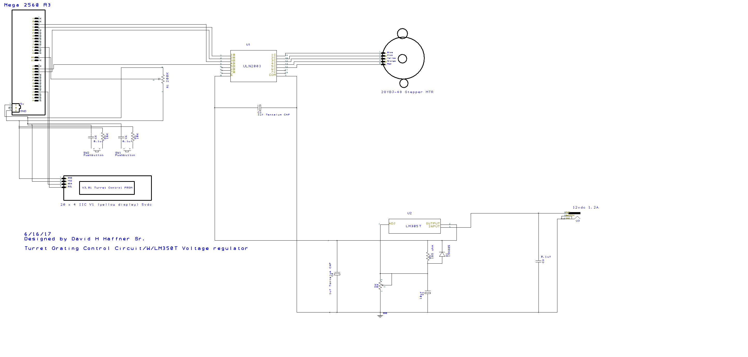
Here is the circuit schematic, I am using a new 20 x 4 LCD display (yellow background) I bought from YourDuino.com, on the schematic I have a 200K trimmer POT, I was experimenting with different values and realized quickly that the source will become to weak for the ADC (internally), resulting in errors, and I'm not going to mess around with buffers and signal conditioning circuits. (Just UR typical 0.1uf CAP(+ end) & 10K resistor to GND @ each button)
So I dropped it back to the typical 10K POT, works just fine.
Some highlights of my code are:
1) NO debouncing programs
2) NO external Stepper libraries
3) Minimal stress imposed on the processor (in my opinion a faster response)
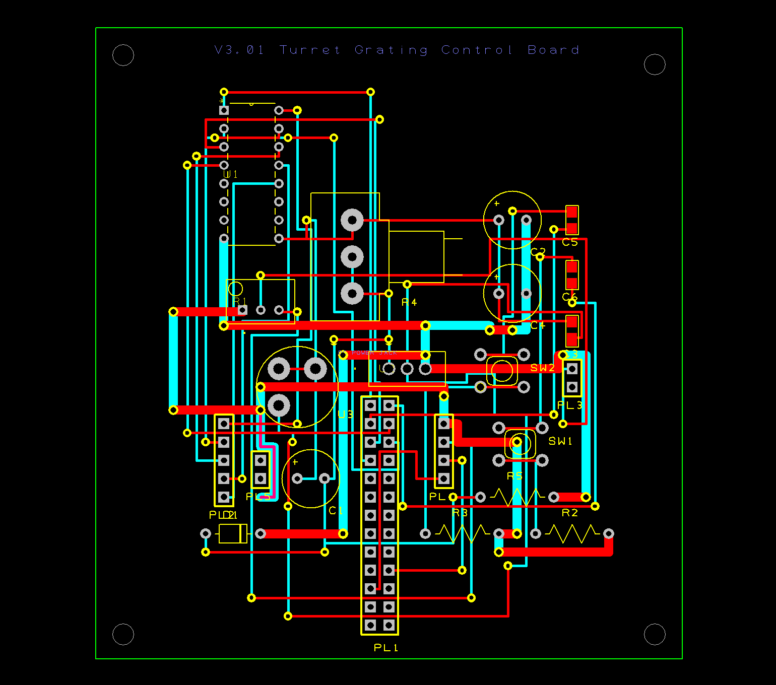
Below is the PCB circuit board, this is the easiest way to interface with the Mega 2560 R3
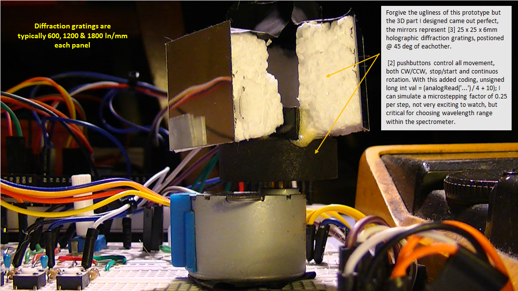 Here is the prototype in the above picture
I designed the turret mount on FreeCad 0.16, and had it 3d printed @ Sculpteo using POM (powdered nylon material) cost of this part; $15.67 US. not too bad :)
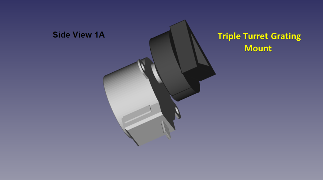 A recap of the 28YBJ-48 Stepper Motor and the Triple Turret Grating Mount assembly
Full project design and schematic files plus gerber files for the PCB can be found in the typical files location on my projects page here :)
Discussions
Become a Hackaday.io Member
Create an account to leave a comment. Already have an account? Log In.
Is your application driving the motors only in one direction? I have used those steppers in a few projects, and found that there was a lot of backlash in the gear train. The only way I was able to get acceptable accuracy was going unidirectionally.
Are you sure? yes | no
Hey Ted! No man, I got these to move both clockwise and counterclockwise, I also have extremely low gear drift, I also can start and stop this motor at will and in the # of steps that I desire with the press of a button.
Also, please see the video :)
Are you sure? yes | no
Maybe I got a bad batch of motors - from what I see on the web, there are many different motors with varying build quality (and specs) sold as the same part number. They probably all would work to open/close vents in your car, which is what I think they were originally for.
I'll check out the video, thanks!
Are you sure? yes | no
The video is worth watching believe me, also here is a code snippet that U may find interesting;
digitalWrite(blue, 1);
digitalWrite(brown, 0);
digitalWrite(orange, 1);
digitalWrite(yellow, 0);
delay(analogRead('...') / 4 + 10);
i--;
if (i < 1) break;
forward(10);
all_coils_off();
}
if (!digitalRead(CCW)) {
reverse(10);
all_coils_off();
if you notice, on forward and reverse, I have countsperrev set @ (10), and here @ delay(analogRead('...') / 4 + 10); I have the delay count @ 10 millisec. I arrived at this point through just experimenting with different step counts and delay times.
I have 3 prototype codings, and all 3 used PWM, and all 3 failed to do what this fourth version has accomplished, at least with this type of stepper motor.
Are you sure? yes | no