 David H Haffner Sr
Practical theory of operation the DAV5 V3 Spectrometer
Raman spectroscopy provides valuable structural information about materials. When laser light is incident upon a sample, a small percentage of the scattered light may be shifted in frequency. The frequency shift of the Raman scattered light is directly related to the structural properties of the material. A Raman spectrum provides a "fingerprint" that is unique to the material. Raman spectroscopy is employed in many applications including mineralogy, pharmacology, corrosion studies, analysis of semiconductors and catalysts, in situ measurements on biological systems, and even single molecule detection. Applications will continue to increase rapidly along with further improvements in the technology. A Raman signature provides positive material identification of unknown specimens to a degree that is unmatched by other spectroscopy's. Raman spectroscopy presents demanding requirements for the detection and resolution of narrow-bands of light with very low intensity and minimal frequency shift relative to the source.
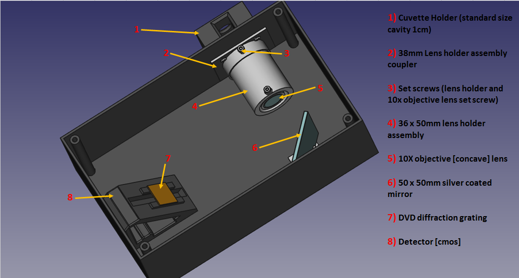
Fig.1 Basic set up, cuvette holder with ½” entrance slit. Front face on enclosure has a ¼” (same size as the cmos sensor) exit slit, which then illuminates a 532nm longpass edge filter (built in to the rear face of the focusing lens assembly) this blocks the laser’s broad band wavelength and allows only the Raman signals (much weaker,) to filter through to the next stage, which is the 10x focusing lens at the front face.
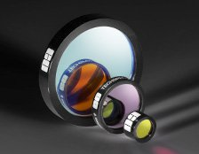
532nm Longpass edge filters ($105.00 EdmundOptics.com)

Transmission curve for the 25mm longpass filter employed in the DAV5 V3 spectrometer. This filter blocks the laser signal and allows the Raman signal through, in turn which is amplified by the 10x objective eye lens before striking the focusing mirror.
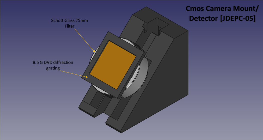
Fig.2 Cmos detector set up, consisting of the JDEPCov-05 cmos sensor, 25mm Schott glass stray light filter and 4.7G DVD piece (I dialed the DVD piece down from 8.5G to 4.7G, 1540 lines per mm is just fine.) used as the diffraction grating.

Fig.2a This was the design I had for the detector mount set up, which I changed to accommodate the Schott filter, which made more sense because the filter needed to be behind the DVD piece and NOT in front. So, figure.2 is the updated version.
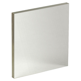
Fig.3 Silver coated protected mirror, 2” square, 3.2mm thick. This is the ONLY mirror used in this set up, the reason is my own research over a year and the precise alignment and filters and focusing lenses used, plus I am using a superior data processing software and live capture program (Spectragryph 1.0 and Spekwin32.)
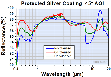
Fig.3a This data plot represents the specifications for the mirror used in this spectrometer, it has a reflectance of 96 – 97 percent @ 45 degrees of angle of incidence (AOI.)
Advantages of this design and set up;
- Detector is easily upgraded by removing the mount and replacing with a new one designed for the new detector.
- No new alignments must be made.
- DVD diffraction grating and Schott filter screw back in place to the new detector mount.
- Raman performance at a much lower cost (average cost for OEM mini Raman spectrometers are at least $6000.00 US dollars.)
- The DAV5 V3 spectrometer can cost as low as $600.00 US, with 95 percent of parts 3D printed.
- Focusing lens assembly provides an all in one performance design by utilizing an inclusive rear filter inlay and front end lens cavity with locking sleeve assembly for easy removal and interchangeability.
- Enclosure lid design has outer lip overhang and 2mm inlay for tighter fit and water resistive properties.
- NO complicated tuning or filter set ups because of its precise alignment and filter design.
This is the beginning of phase II, assembly and practical testing.
Discussions
Become a Hackaday.io Member
Create an account to leave a comment. Already have an account? Log In.