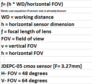
 David H Haffner Sr
Mathematically speaking, the idea behind this design was based on a DIY Raman spectrometer I ran across a year ago, its simplicity caught my attention and after studying their research results, I was convinced I could build one using a cmos sensor based design since these cmos sensors operate quite well in the green wavelength range of the spectrum.
The JDEPC-05 turned out to be a surprising little detector, one, because it had a great spec sheet with a lot of detail and because of this, I was able over time and much trial and error, to come up with my present design concept.
One critical factor with this sensor, is removing the IR window underneath the lens, it does introduce a small amount of extra noise but expands the dynamic range when readjusting focal length calculations. Keep in mind though that a cmos has a wavelength limit of 1100nm, which is fine for this design using a 532nm green laser source.
Now, with much research and using these equations, I have successfully aligned and focused the sensor to mirror ratio in relation to the relative horizontal and vertical spectral image striking the actual sensor substrate.
The factory specifications for the JDEPC-05 has a focal length of 3.27mm @ 48 degrees. Since I am using a 32mm achromatic coated lens, (to capture more incoming light,) coming from the exit slit, I had to not only adjust the focal beam width of the image to the mirror but the one going to the sensor, since the actual sensor size is 6.34mm (0.25’’.)
Here is the math;
 Focal distance from apex of 32mm lens to mirror is; 70mm. From centerline of mirror to sensor is; 65.02mm.
F= (6.34mm X 65.02mm/48 degrees)
H= 8.5mm (0.33’’) focal distance from mirror to sensor
F= (6.34mm X 65.02mm/64 degrees)
V= 6.43mm (0.25’’) focal distance from mirror to sensor
Entrance slit width= 6.34mm
Exit slit width= 100um
Laser beam width= 0.37nm (as of present.)
Distance from apex of sensor lens to DVD diffraction grating is 3mm (this may have to be adjusted slightly by hand, using a CFL spectrum as your focal guide. You need to image the CFL spectrum in “live capture” mode so you can see the lines come into focus…yes, it is very difficult but I have no other way of resolving this procedure.)
There is no need to use a very expensive holographic or other diffractive piece other than the DVD piece, if you adjust the alignment correctly. I will outline this procedure next;
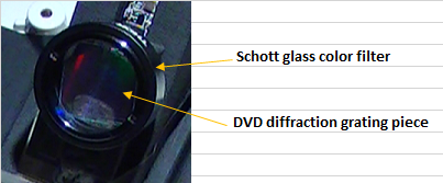
In the figure above, you see the DVD piece secured in the filter housing by a locking sleeve, the entire filter housing fits on top of the cmos camera mount, and can be rotated in either direction. This feature allows not only DVD diffractive alignment, but provides an accessible method for removing the diffraction grating for replacement.
This is where the distance is measured from the bottom of the filter glass to the apex of the cmos lens (3mm approx.) In this way, you can easily utilize an inexpensive DVD R/W CD to use as your diffraction grating and it will work just fine.
This one is a 4.7G 1540 lines per mm piece. I have used the 8.5G pieces before and the resolution is a little sharper, but you will sacrifice your wavelength range by doing so, and in this case, this diffractive value is working great.
So, alignment is quite easy, just turn in either direction very slightly until you have the lines as vertical on the screen as possible. Now, depending on the processing software you are using you do need to see the spectrum in real time, to align it correctly.
You will know it is aligned correctly by watching the green (546nm peak) you should have at least two sharp peaks with NO clipping, if you get clipping just attenuate the signal slightly with an NG filter, (doing this though, keep in mind may change the wavelength values at the peaks and change their shape, try to find the best balance and keep it there.)
In my next log, I will explain the theory of operation behind my laser collimation tube design.
Discussions
Become a Hackaday.io Member
Create an account to leave a comment. Already have an account? Log In.