 David H Haffner Sr
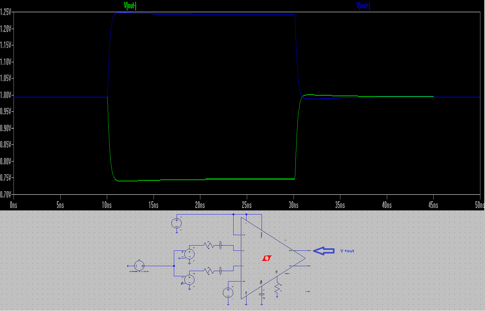
*UPDATED* well I just found out why there is a 9.09k resistor @ R5 on the schematic, it gets rid of that "ringing" at the peak at rise time @ 10ns pulse.
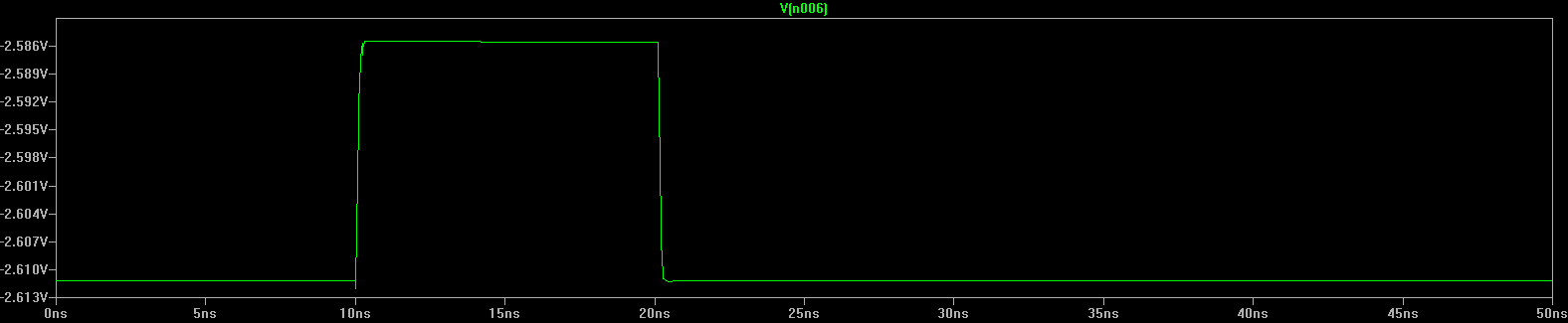
Thanks to @Ted Yapo for helping me fix this simulation on LTspice. The "real" op amp is in place -AD8021,
the true parameters are inputted at the pulse generator (pins 7 and 8, are not present, for some reason spicemodel file omitted them for error?) so I'm not worrying about it for now, I just needed to know that the output at pin 6 is -2.5v when R4 (which is a trimmer pot 2k,) is adjusted to 1.83v. 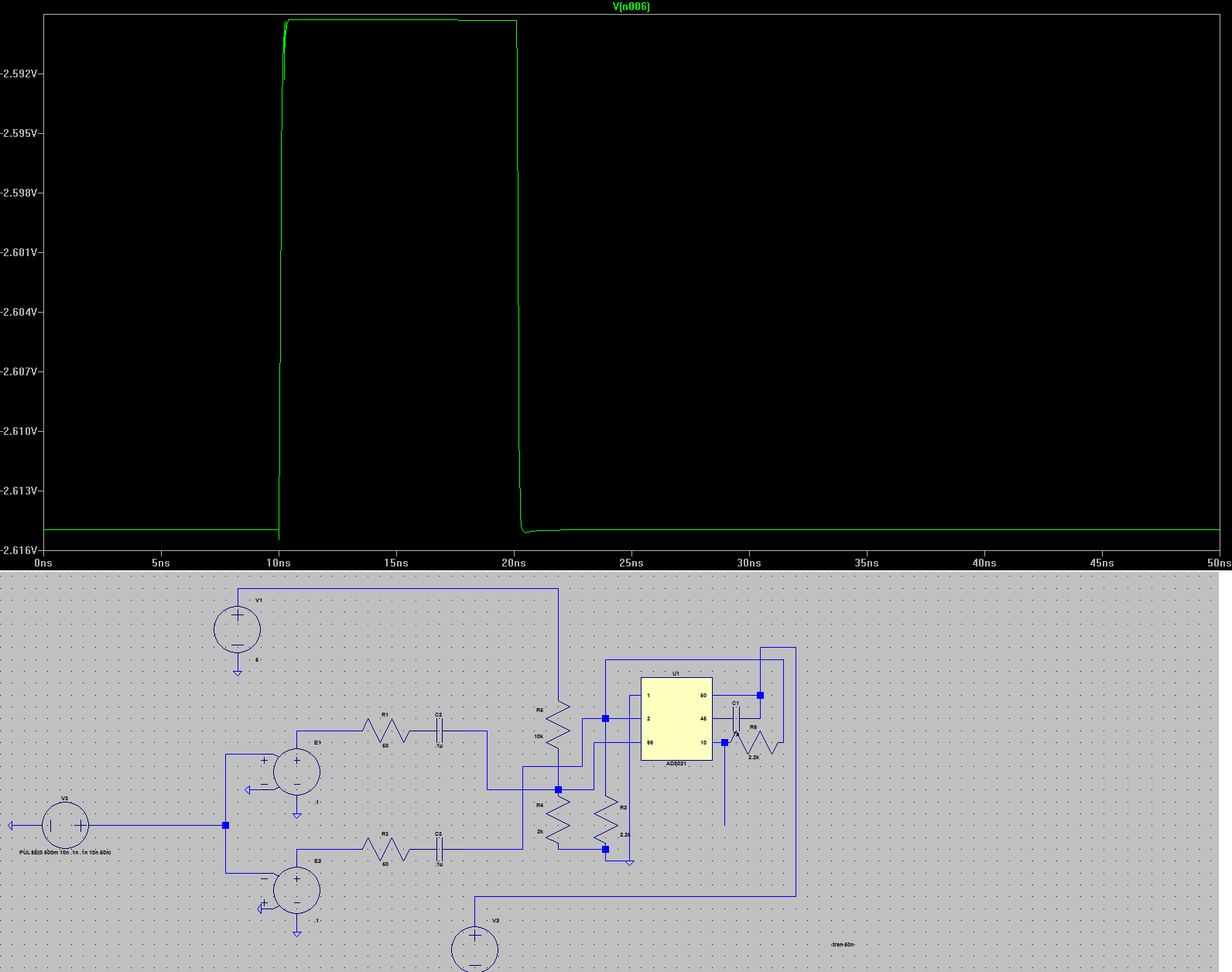
The .ASC file will be available for this sim on my files page.
I corrected some of the pulse generator values to what they are exactly on the data sheet and schematic, 10um and 20um. Something still doesn't look right, from rise time to fall time. Also I just wanted to add that, I may be spending a lot of extra time on this aspect of my build, but I have learned through experience that, it is better to build it right the first time, so I don't have to de-solder everything and do it over again!
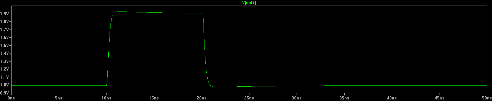

*UPDATE* Here is the .asc file for the LTC6417 op amp and also the logic analyzer screen capture for the MCLK for the TCD1304AP chip;
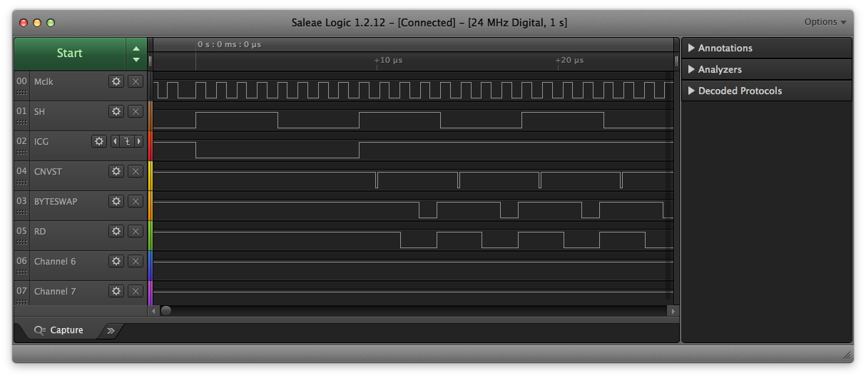
Above picture - TCD1304AP CCD chip (Toshiba)
Since I am using the AD8021 op amp as a unity - gain inverter to run the ADC (AD7667,) I needed to run a sim to check out some performance issues that Dave Allmon is having with the MAX232. Apparently it cannot keep up with the AD8021, so he has re-designed the entire schematic and added a new power supply.
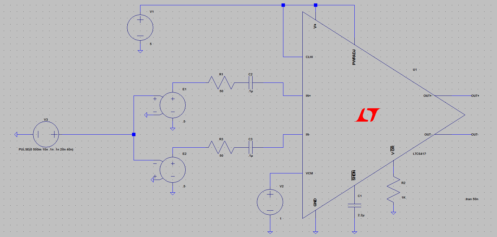
My mods will still work he said, but there may be an issue with the MAX232. I am going to upgrade to the MAX232EIN (16-pin dip,) now on LTspice there is no AD8021 op amp, even though I created one it doesn't work right, so I used their newest version which is comparable to the AD8021 and ran a sim test circuit.
My question is, at R4 I have variable resistor (2K,) to adust voltage at pin#3, it has to be 1.83v. When I run the sim on LTspice, I know I am using a different op amp with slightly different variables, but I am getting 1.25v out of what would be pin# 6 from the op amp?
Do you think I may be over driving the circuit (current wise,) with only a USB power source?
Discussions
Become a Hackaday.io Member
Create an account to leave a comment. Already have an account? Log In.
I downloaded your simulation an ran it here. I see why you don't need a DC bias path for the inputs - there's one internal to the LTC6417. The LTC6417 and the AD8021 aren't too close in functionality, though - having to set the output common mode voltage on the LTC6417 is a prime example. I wonder if the spice simulation using this other amp will mislead you.
You can add spice subcircuit models to LTspice, so you could add a model for the AD8021 and simulate the "real thing". Here's a link to the SPICE model for the AD8021
http://www.analog.com/media/en/simulation-models/spice-models/ad8021.cir
(you have to agree to the license to download it). Here's a video from LTC on how to add third-party models:
http://www.linear.com/solutions/1083
My suggestion would be to add the AD8021 model and simulate the amp you'll really be using. Amps like this are unique enough that it will make a difference.
Are you sure? yes | no
Thanks Ted for taking the time to do this, I truly appreciate it. I'm going to the website now, I'll let you know what happens soon.
Are you sure? yes | no
Can you post the *.asc file for the simulation; it's difficult to read the part values in the image, and running the sim here might provide some insight.
One thing that jumps out is an apparent lack of bias path on the inputs (both AC coupled with a capacitor). I can't tell what amp you have in there from the image, but I can't think of too many where that's OK. You typically need to have a DC path for bias currents to the input pins even if you are going to AC couple the inputs.
Are you sure? yes | no
Hey Ted, ok I'll post the file, the amp I had to use is the LTC6417. I'll also post the actual logic analyzer screen capture of the Mclk values for the TCD1304 chip.
Are you sure? yes | no
Het Ted, ok I updated the info one the project log and also uploaded the .asc file to my "files" section on the fron page, can't miss it it says LTC6417 op amp in the description box.
Are you sure? yes | no
Het Ted, ok I updated the info one the project log and also uploaded the .asc file to my "files" section on the fron page, can't miss it it says LTC6417 op amp in the description box.
Are you sure? yes | no
Hey Ted, ok, I have the pulse sequence correct for the MCLK; 1st pulse is 10um, 2nd pulse is 20um.
Are you sure? yes | no