 David H Haffner Sr
Updated code can be found here: Arduino Playground Sketches/Code snippets
This is section 3 for the stepper motor controller interface unit, in my previous posts I had discussed and shown the use of a 1 x 4 membrane push button panel, well…at $2.00 it performed poorly so I’m not going to rely on it so I designed my own 4 button keypad on DesignSpark and the schematics are posted here.
The keypanel is being manufactured as I write this by PCBway.com.

This is my schematic design of the 4 button control key pad, dimensions: 48 x 36 mm ( 1 7/8″ x 1 7/16″.)
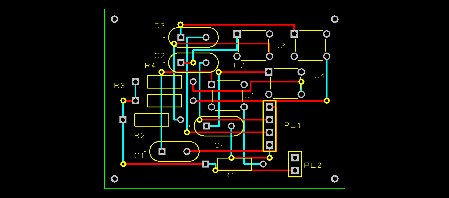
Above is the PCB lay out.
Here is the BOM (bill of materials,) which together only costs $3.84 per board to make and it is far more reliable than the membrane keypads.
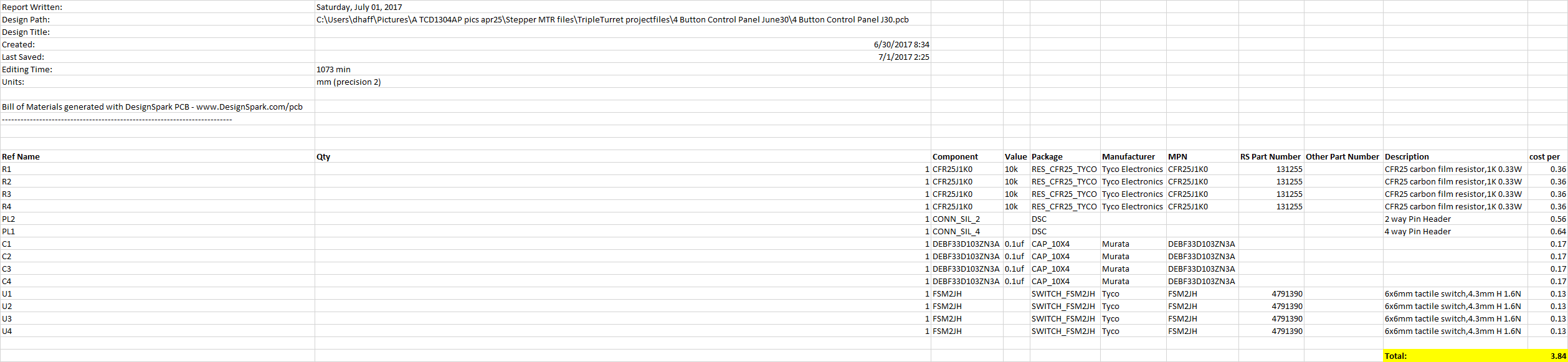
This button control keypad coupled with the motor control interface module will provide superiour stepper motor performance and control, even for a low end stepper motor such as the 28YBJ-48.
This is another example I wanted to share of cost effective measures I have integrated into my overall project designs (most of the time because of budget constraints,) but I have been able to produce many high end parts that would otherwise cost many hundreds of dollars had I bought them outright.
I also wanted to highlight the processor that is at the heart of all this, the Arduino Mega 2560 R3, I think this device is highly underrated and it’s versatility is really quite amazing! I like it number one, because of its a very low power consumption and extra ports, not the fastest machine around but it doesn’t need to be for the applications that are demanded of it.
Reliability and performance are far more important to me than speed.
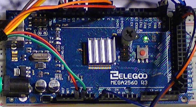
As you might notice on mine here, I have a small 15 x 15mm aluminum heatsink on the CPU, only because I did notice that it does get a little warm now that I have her doing a lot more than usual, It does reduce overall temp by about minus 12 celsius.
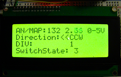 Lastly, I did want to talk about some of the new features I added to the control program, as you can see on the image above to the right of the AN/Map, I added a “float” so I could read the Ref voltage from the ADC @ the stepper coils that control direction on the stepper motor. The range is from 0 to 5vdc and the readings are in real time, when the buttons are pressed the 4th line shows the button pressed and the 3rd line shows the coils activated.
As the motor spins in the desired direction the voltage is shown on the AN/Map as the coils are activated. This value is controlled with a 50k trimmer POT at pin# A0, usually a 10k POT is used because of signal loss at the ADC but I have been experimenting for awhile and I am convinced that at 50k there is enough signal and very little loss at the ADC, the benefit of this is more sensitivity and better response time from the button control pad, thus a faster response at the diffraction grating turret.
Updated code can be found here: Arduino Playground Sketches/Code snippets
Discussions
Become a Hackaday.io Member
Create an account to leave a comment. Already have an account? Log In.