 Mike Rigsby
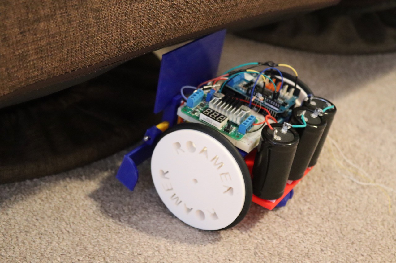
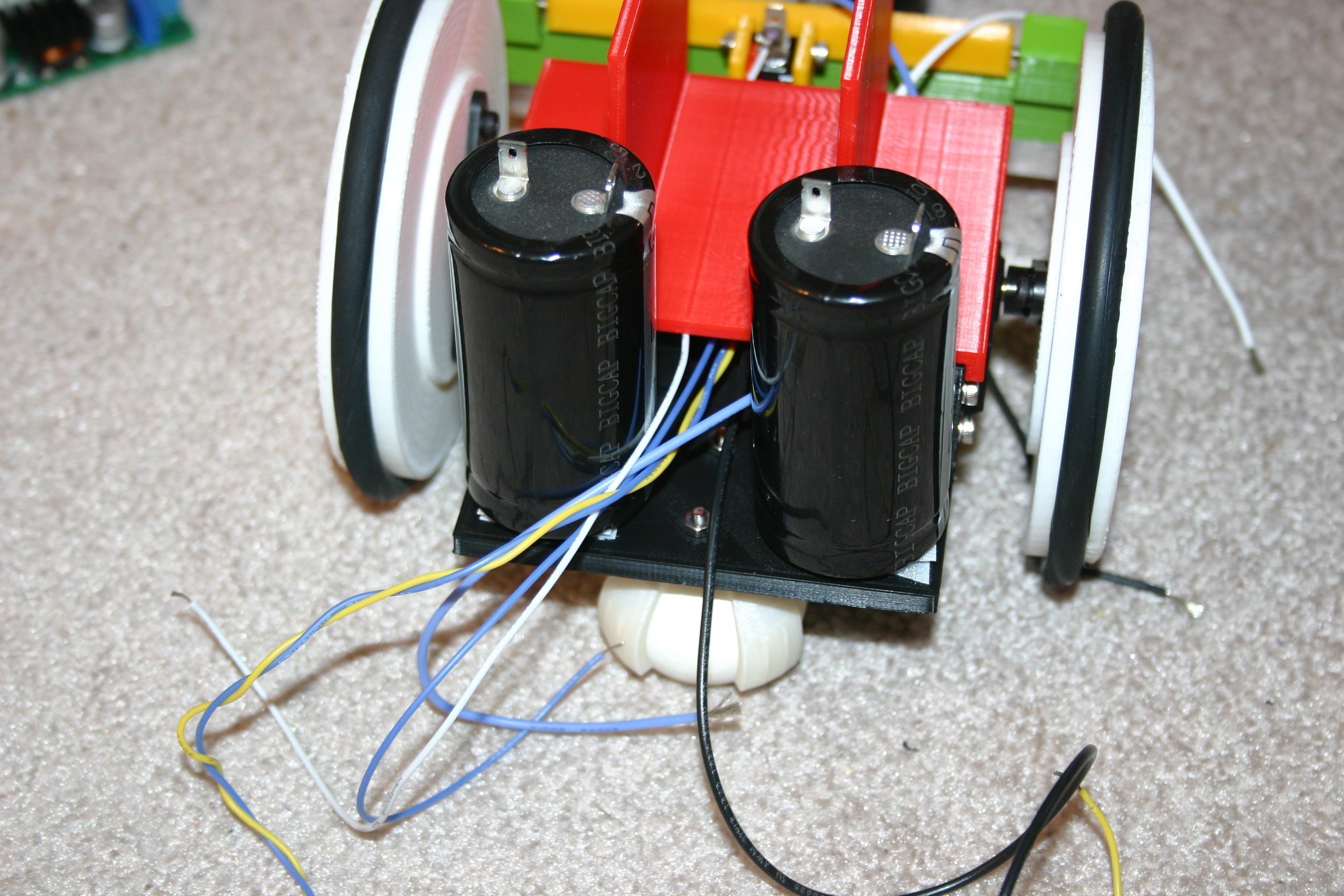
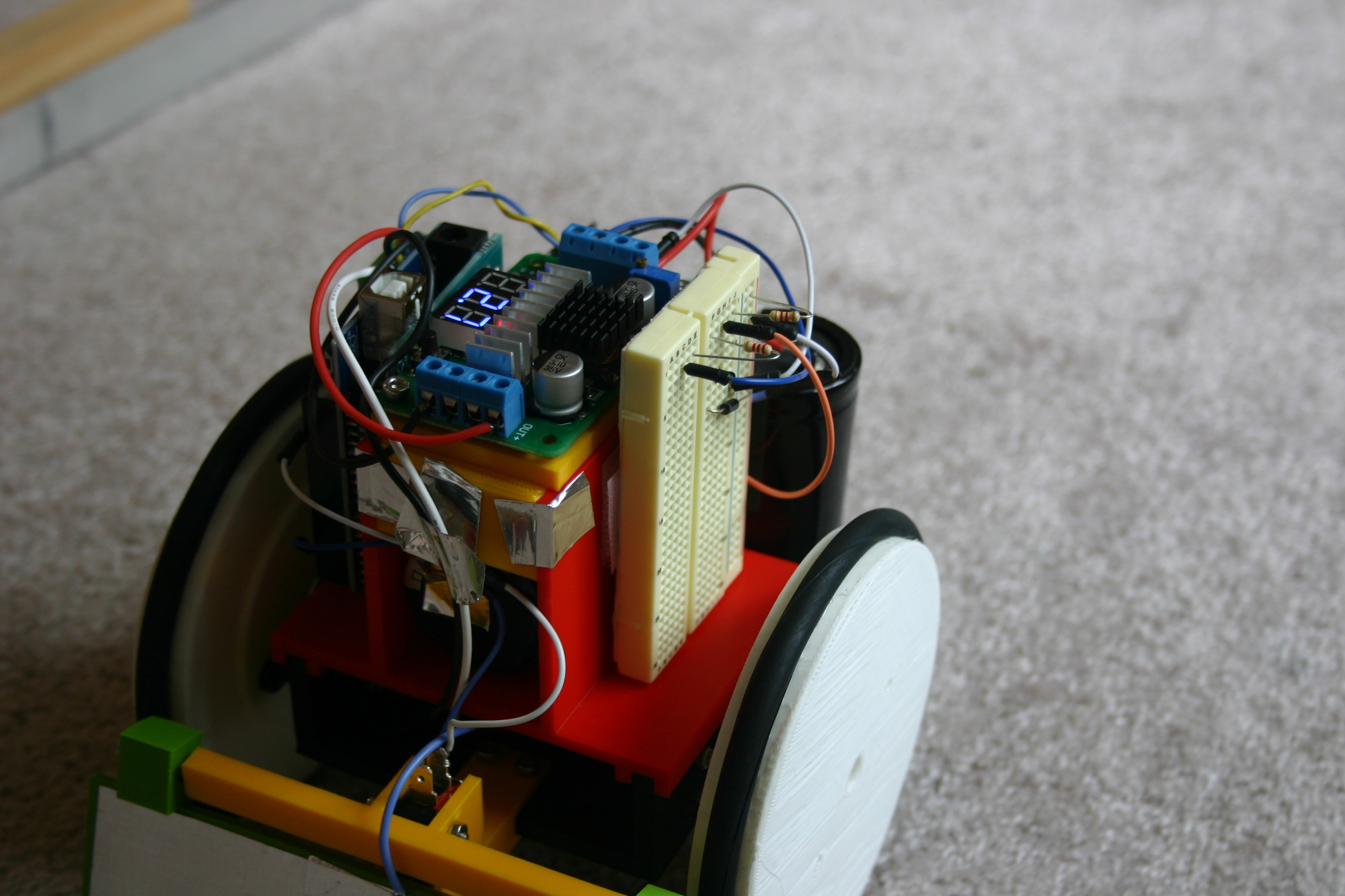
Battery life and charging time are significant challenges for companion robots. Aibo, for example, runs for one to two hours followed by a three hour recharge period. If Aibo is charged/discharged once per day (not much of a pet if the thing is resting 22 hours per day), the (not user replaceable) battery will lose half of its capacity within two years (refer to Aibo website). Roamer, using super capacitors, can easily be active 16 hours per day (more time running than charging -- with very little capacity degradation) and she can "sip" a bit of charge anytime the station is handy.
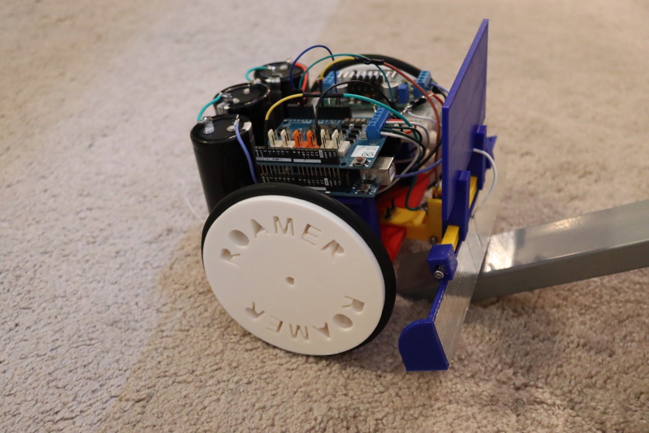
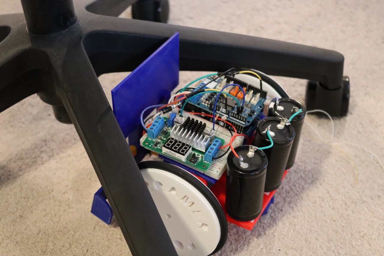
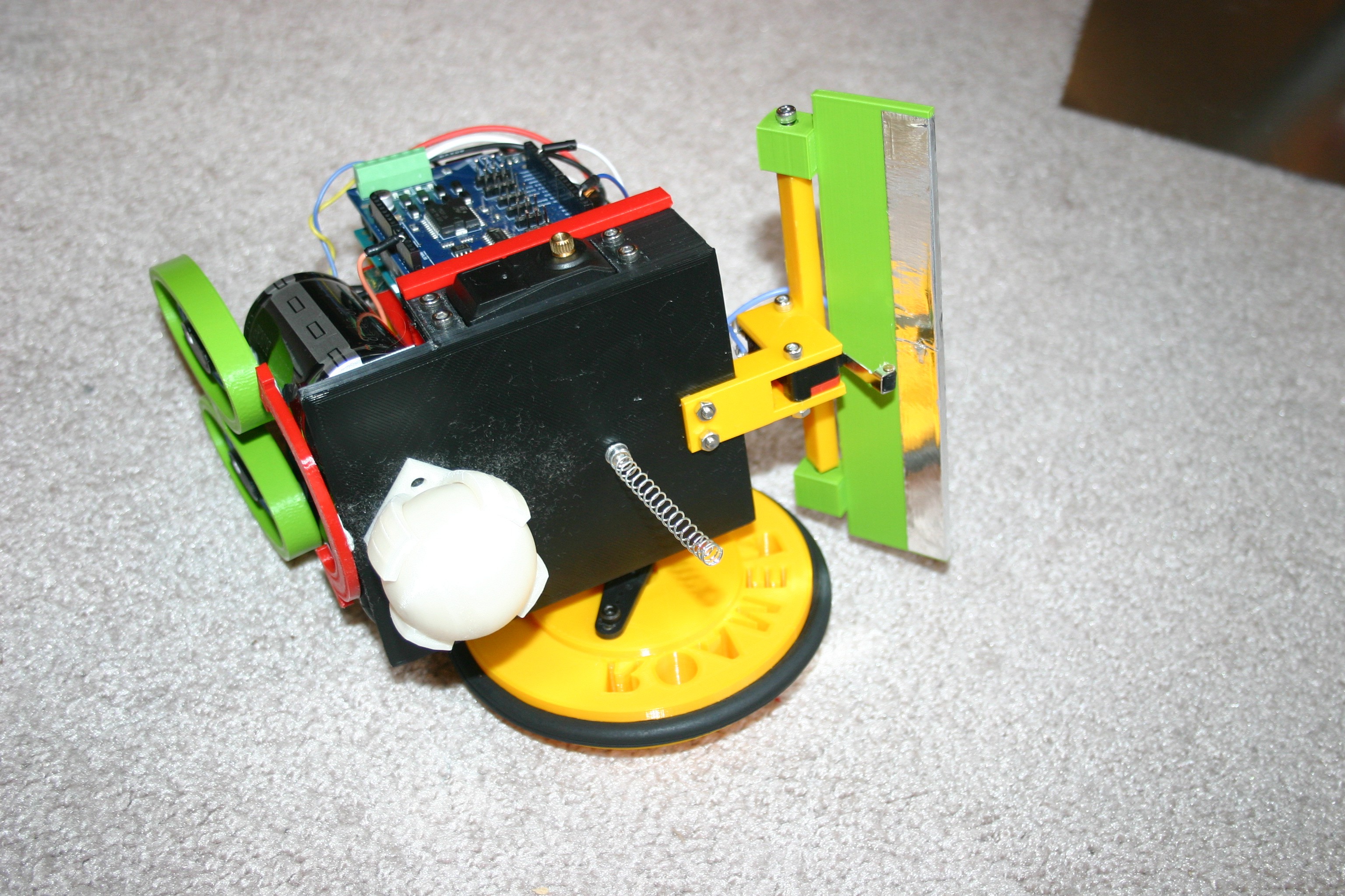
Set Roamer on a charging station. When charged, she wanders around randomly, sometimes coming into the charging station and topping off. When the room gets dark (night), Roamer “rests” on the charging station. At dawn (light), she resumes her journey to nowhere, charging at every opportunity.
Here is a real time view in action.
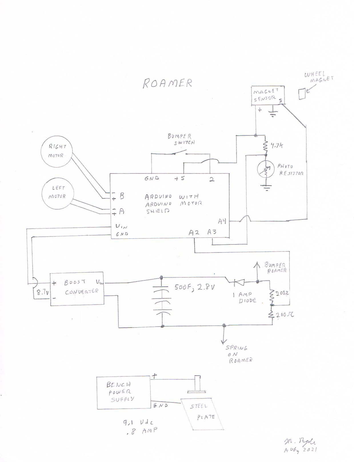
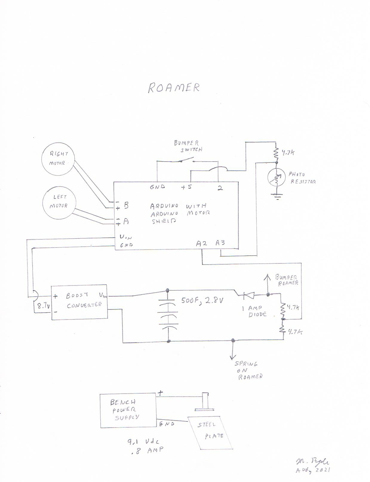
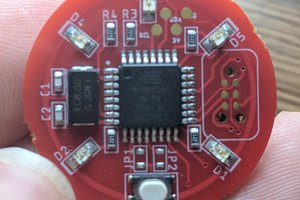
Here's the schematic.


 Charles Dean Modrich
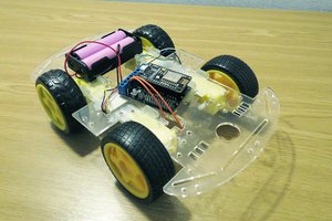

 Dan Fruzzetti
 Daniel Roseman
where can i purchase one if I don't want to build myself?