 Bin Sun
[From Mayo Clinic] Amyotrophic lateral sclerosis (a-my-o-TROE-fik LAT-ur-ul skluh-ROE-sis), or ALS, is a progressive nervous system disease that affects nerve cells in the brain and spinal cord, causing loss of muscle control.
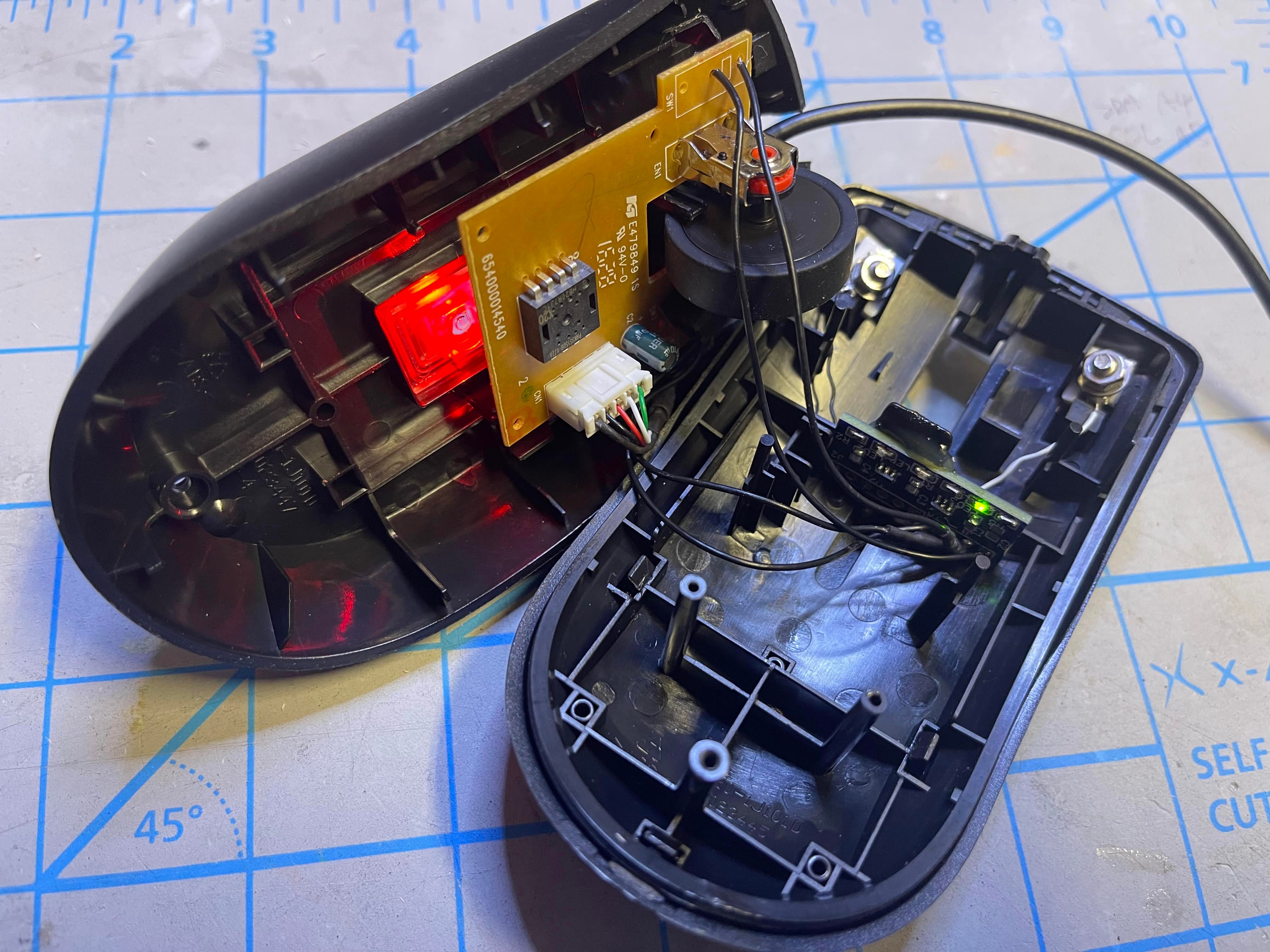
Imagine your fingers are stiff and difficult to click the regular mouse button which requires you to lift up the finger and press down. The idea behind this capacitive touch mouse is to change the mouse click action to lateral movement of your finger in order to touch the surface of protruded electrodes. In this way zero click force is required, and requires much less hand muscle function. This is different than touch mouse on the market which still requires lifting up the fingers to touch.
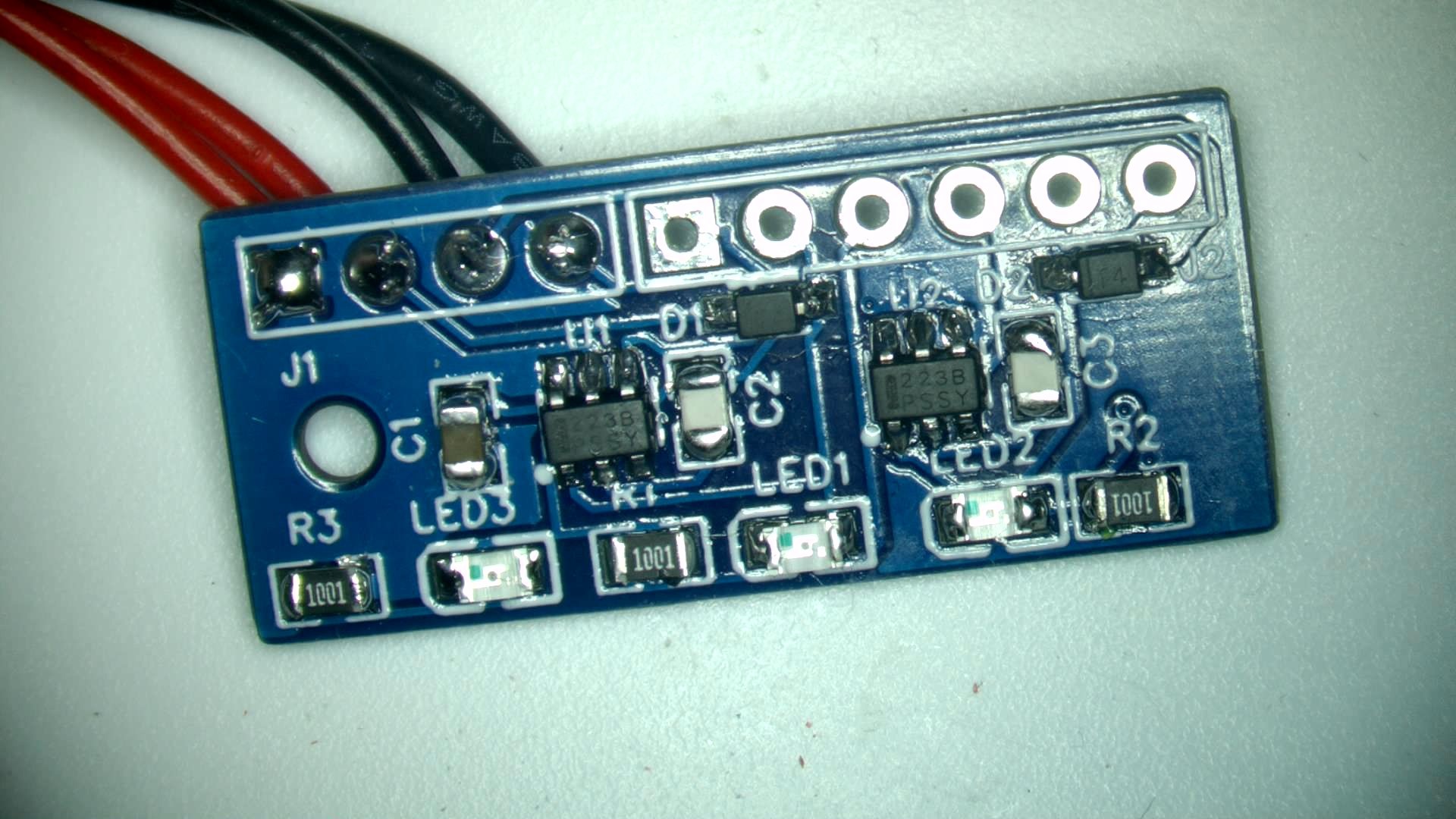
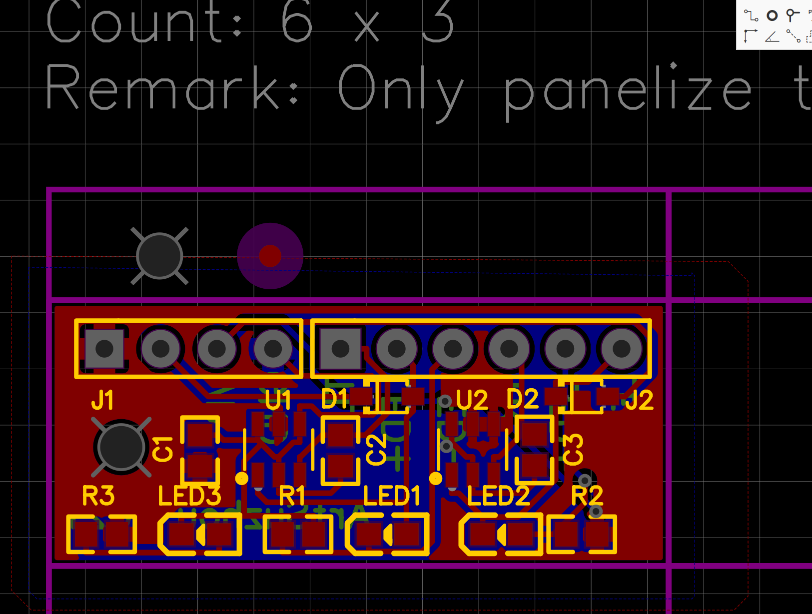
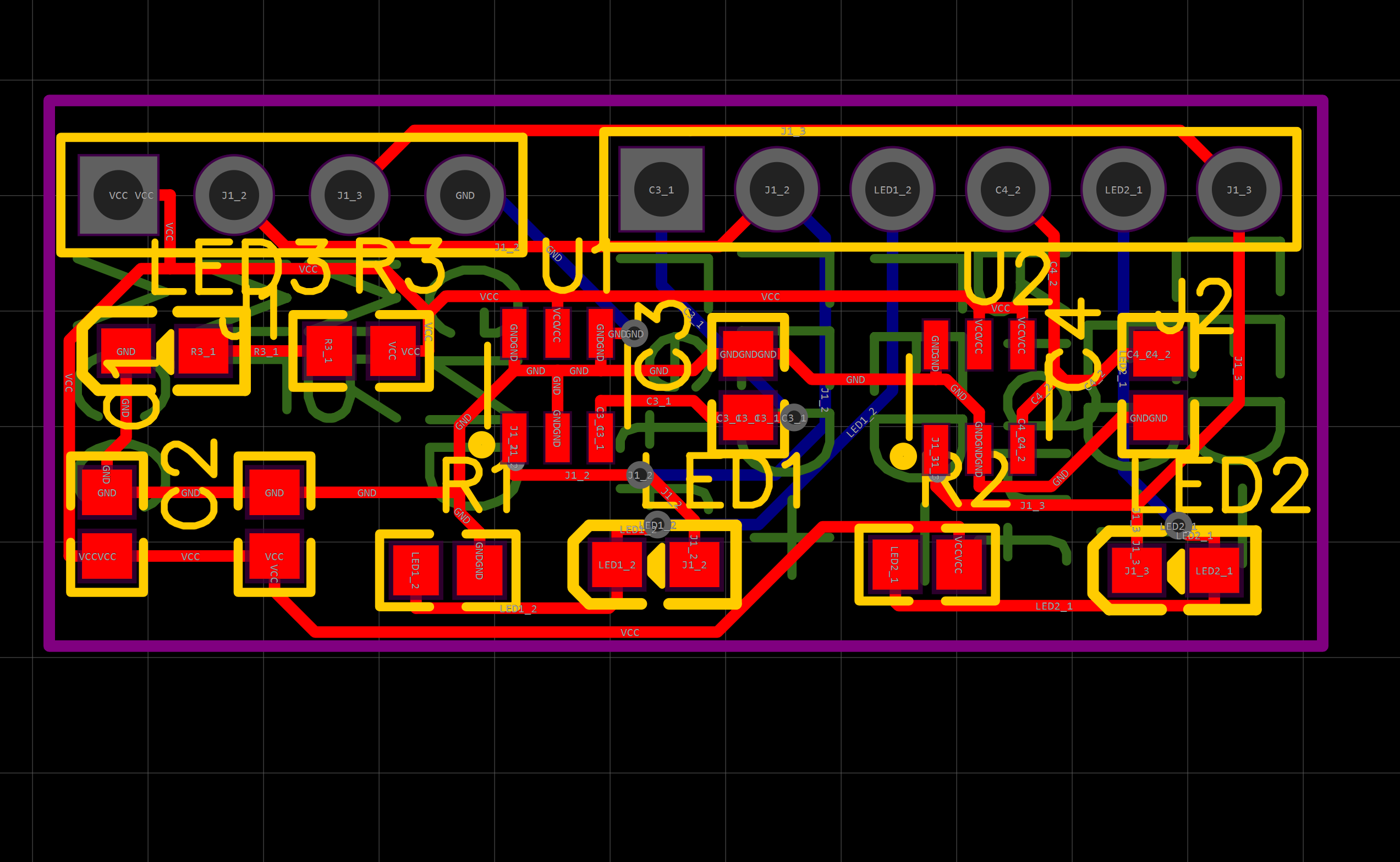
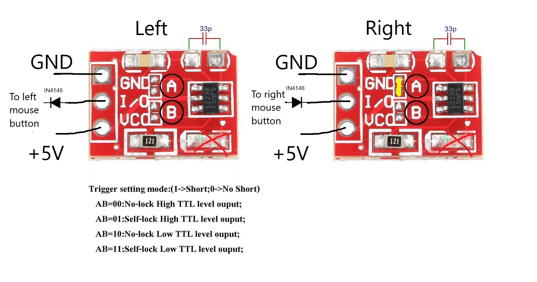
The design is to hack a standard computer mouse with TTP223 capacitive touch sensor module, and to replace the mechanical microswitch for the left and right mouse buttons with the capacitive touch sensor. No other hardware or software modifications is required. The modified mouse with capacitive touch buttons performs and functions in the same way as before.
This project achieved the goal of hacking hardware to be more user-friendly and inclusive to all types of mobility. It is also beginner-friendly, as all the parts can be sourced inexpensively online and does not require any especial tools or software.


 Elecrow
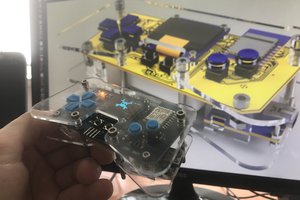
 Jeremias
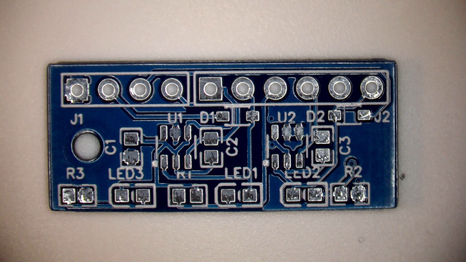
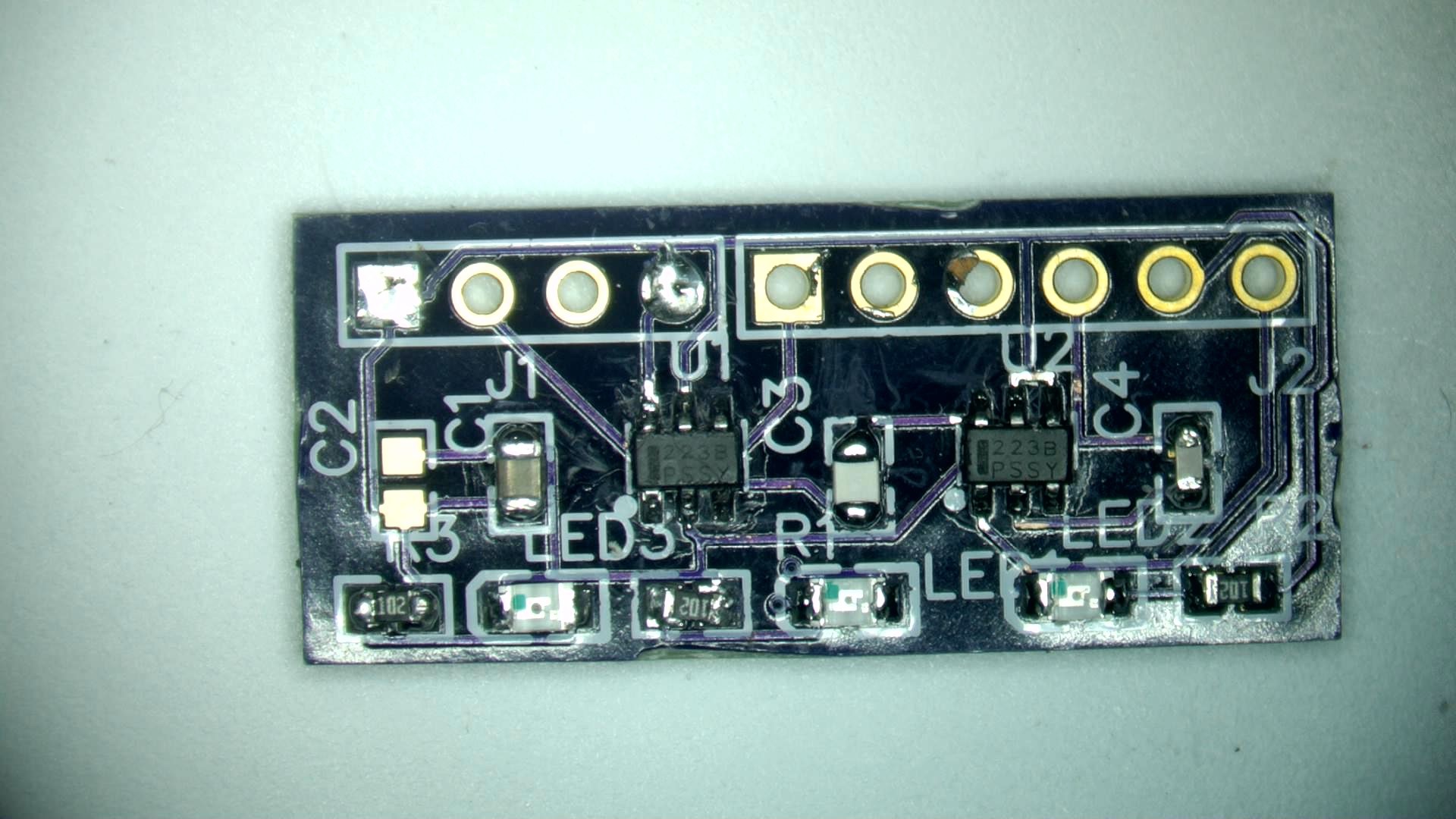
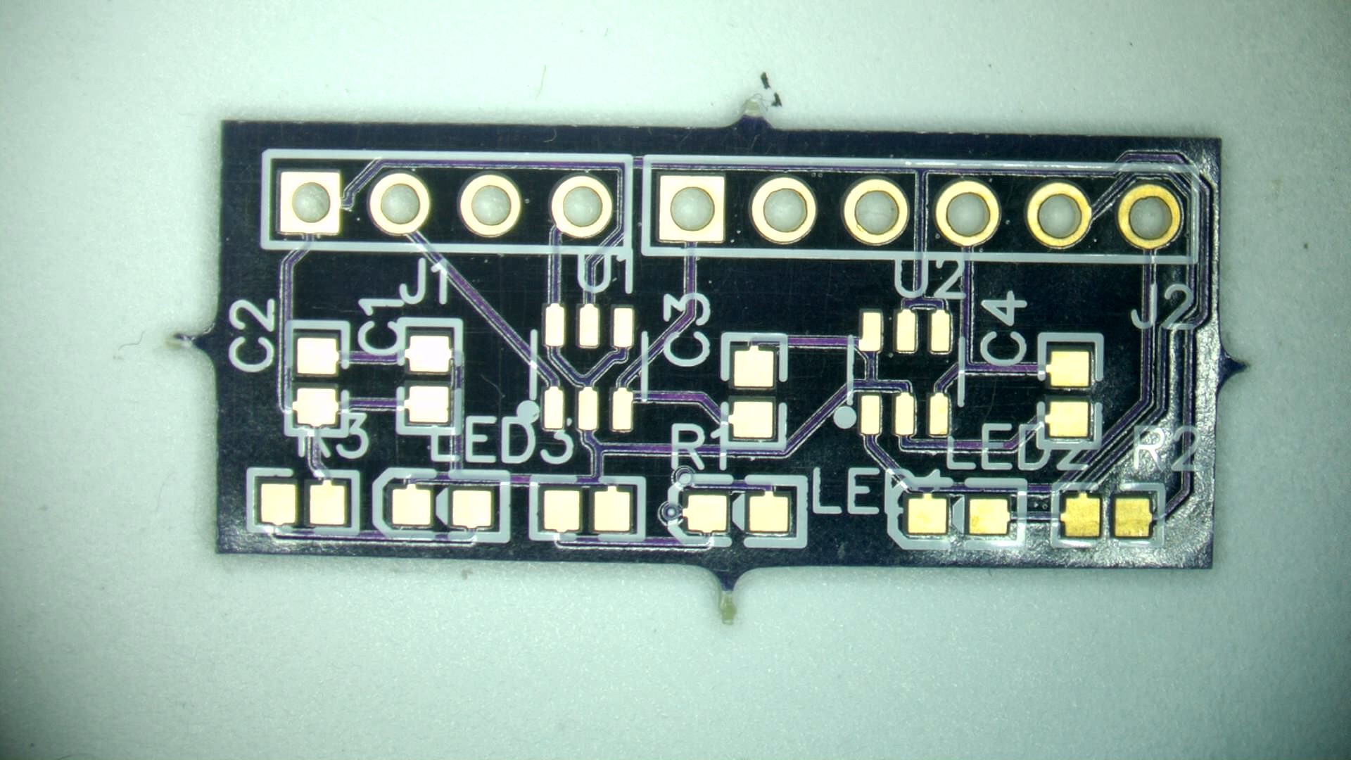
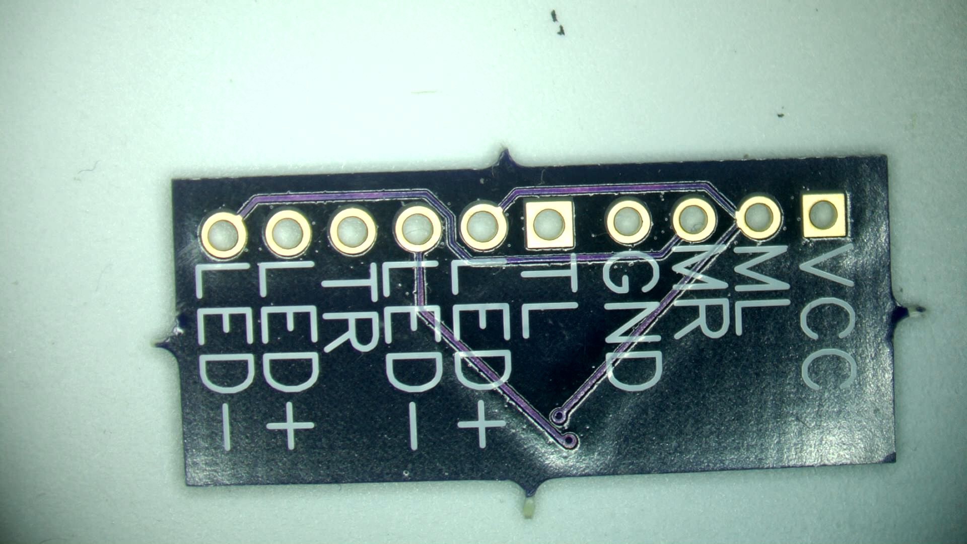
This project is still ongoing. After successful testing of the prototype using the off-shelf TTP223 module, I'm going to make dedicated PCB with smaller footprint and better efficiency. Also I have made several of them and shared with people with hand mobility for testing. Stay tuned.