The Story
I like to play computer games and I spend quite some time with Elite Dangerous. Playing with keyboard, then with a Logitech stick and a gamepad. But for me this was not really working.
The next idea would have been HOTAS. But for me they are too expensive and the are not really doing what I imagined. So I decided to try building my own stick - knowing that this would be a long way.
I spent 2 year of tinkering (part time of course) to get to where I am now. But it was well worth it so far. Not only because of the stick I have now. But even more because of the knowledge I build in different fields be it, soldering, wood working, electronic components, CAD, 3d print and coding the thing.
So if you are thinking about building your own - go for it! It's fun and educational :)
The vision
So what did/do I want for my "perfect" gaming controller?
Sticks
One stick is by far not enough! Make it 2 better 3. And I hate those big junky sticks you can buy - I want them small and handy.
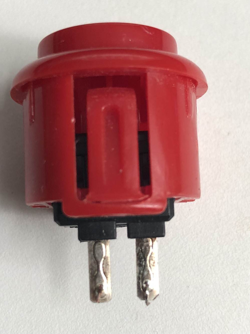
Buttons
Big buttons and lots of them. Not the tiny once - I have big fingers ;)
Throttle
A throttle is a must for all flight and space sims!
Immersion
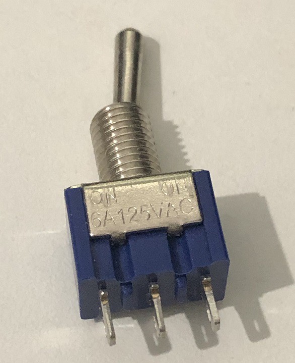
I wanted some immersion. It is so much more fun to have a physical switch/toggle to lower and raise your gear. Or arm your weapons with a protected master switch.
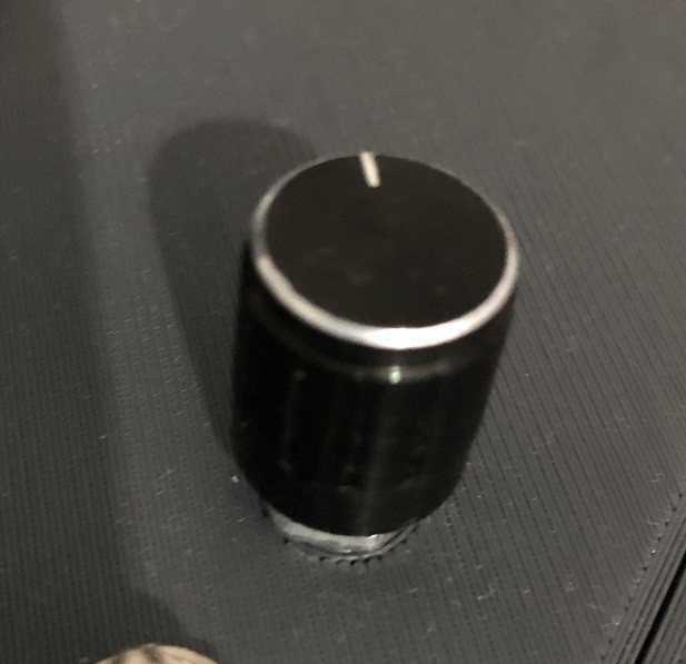
So switches, rotary button thingys - lots of them
Display
There would obviously be a need to show the status of some components like "is the left stick analog now or is it acting as a "wasd" keyborad output. LEDs are cool but a display can show much more... So a display it is.
Nobody starts as a master
It is very important to not set the goals to high to start with. Have a vision but narrow it down to steps you can do!
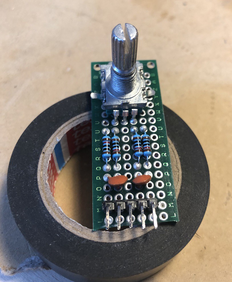
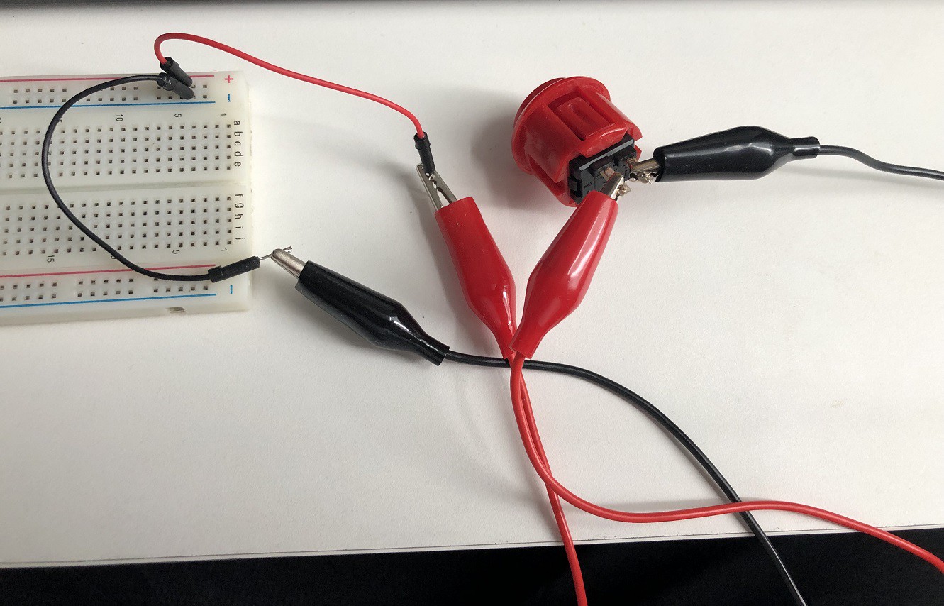
My first stick looked like this
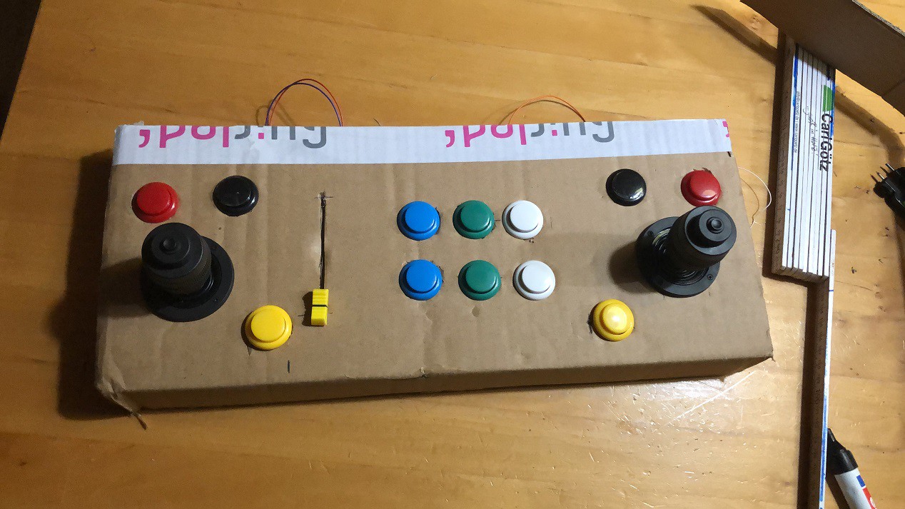
The whole purpose of it was to get a possible layout and see if I can get some components to work
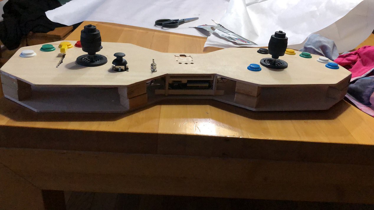
When this was achieved it was time to build a more durable version and add some more components and get them to run. So I ended up building a wooden case, added a 3rd analog stick and the first switches
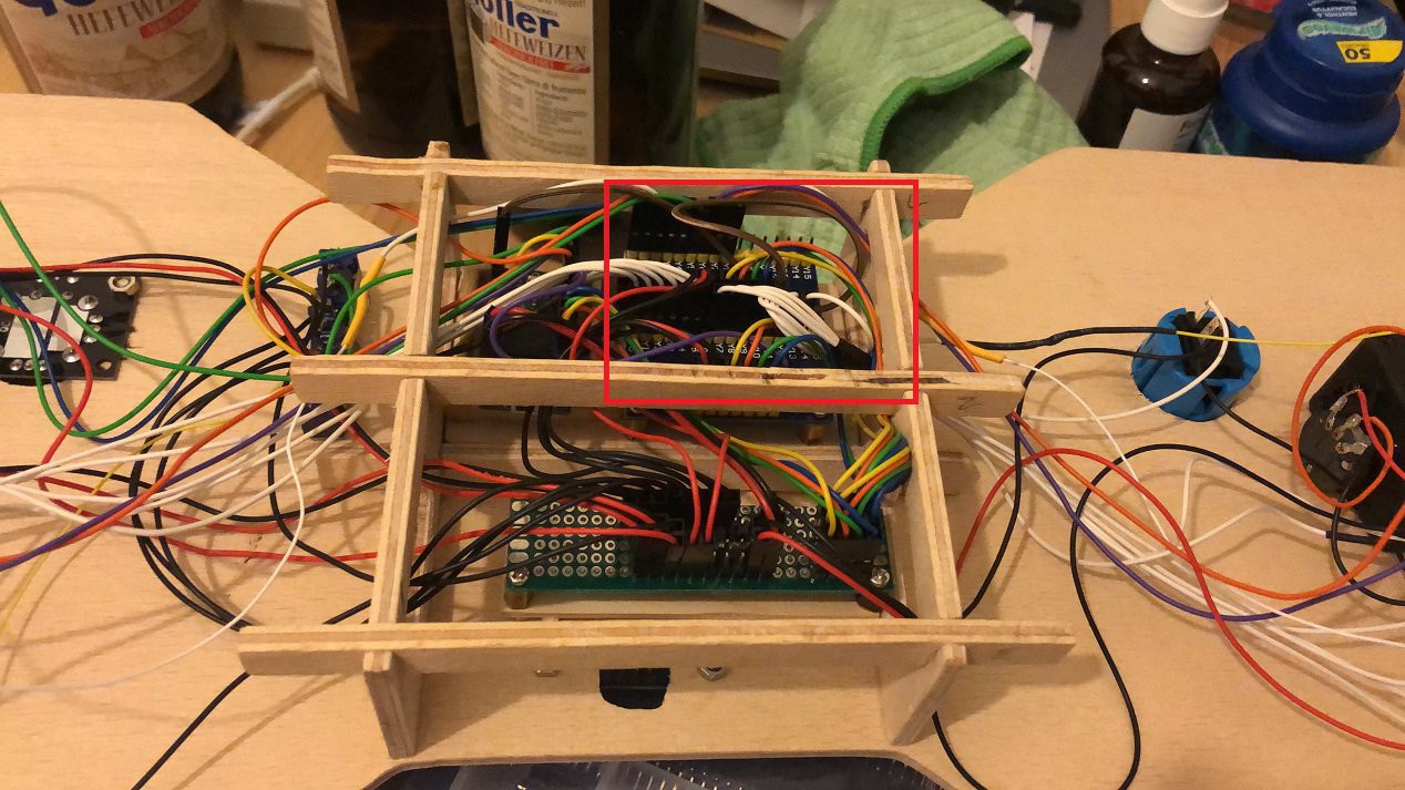
The wooden stick worked quite a while but the wiring and especially the placing of the breakout boards was not very well done and some contacts tended to loosen themselves. So it was time for the next level- Go for a even more sophisticated case and better wiring approach - learning form the previous 2 verions. So I decided to construct one in CAD and go for a 3d printed case
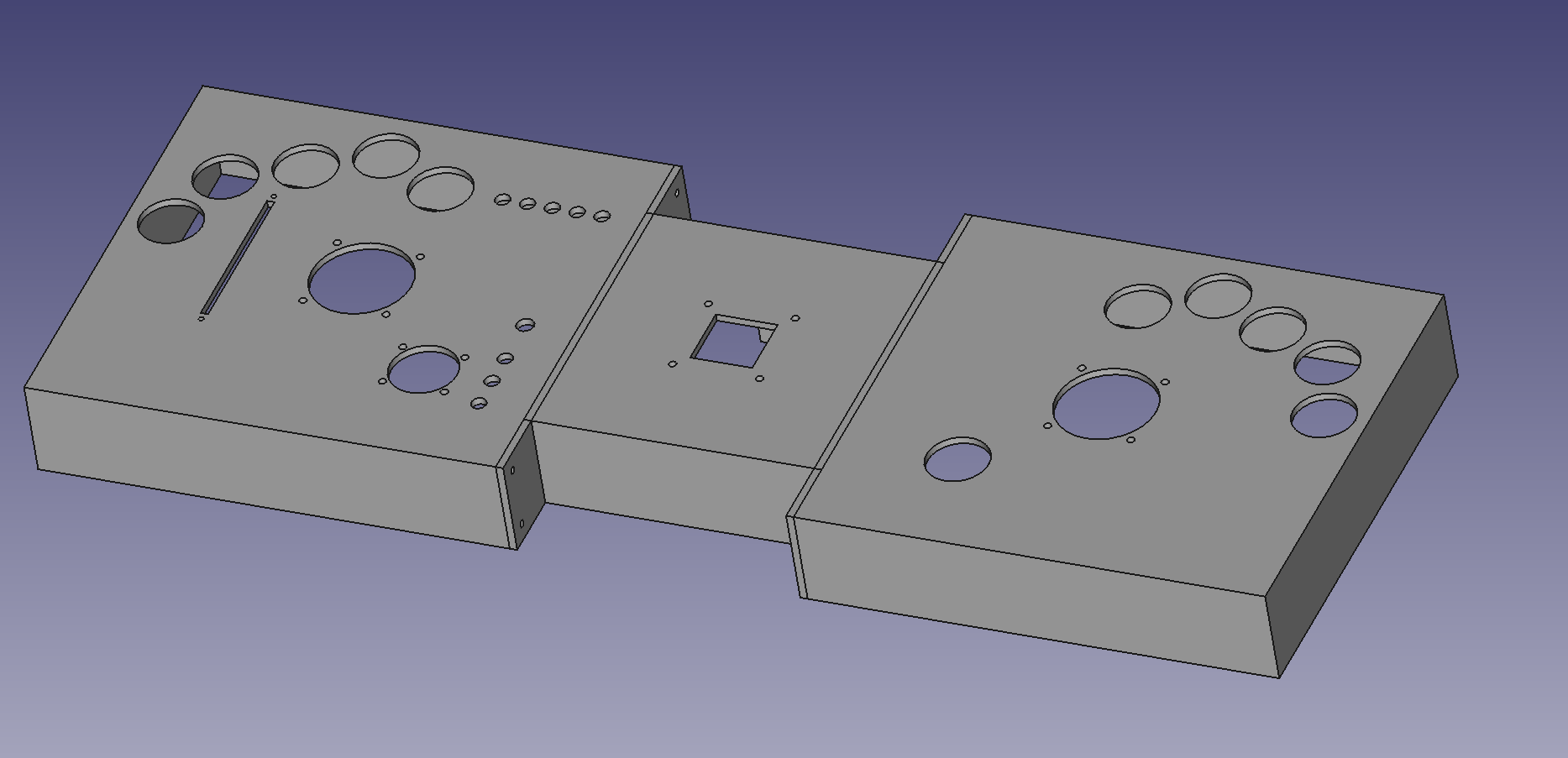
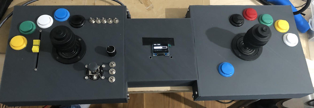
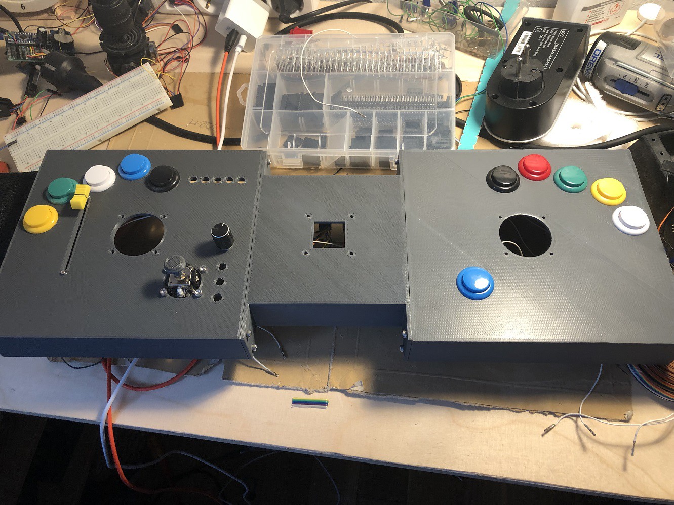
Which currently looks like this
Starting this project here on hackaday... I decided to restructure it and go into much more details in the Instructions. Not putting so much info in the logs - for a more structured approach.
So forget about the logs I did in the past - head straight over to the instructions. I will do the major work there (well at least that is what I plan to do now.
Feedback is very welcome so feel free to add your comments!
Stay tuned!


 Metalnat
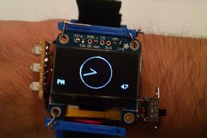
 davish
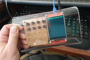
 T. B. Trzepacz
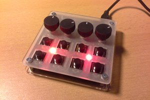
 Stefan Lochbrunner
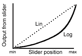
Hi mate really nice guide, thanks I m going trough the same learning process I was wondering if you will upload a full sketch or some tips on logarithmic signal manipulation. thanks for sharing all this information.