 Ulrich
The idea for the schematics was to stay as small as possible. Thats why I only choosed to have a bare miniumum of components on the logic board.
At the current project situation I could not decide between a different bunch of sensors.
That the reason why I added a connector to replace Sensors on the fly.
Choosing the components:
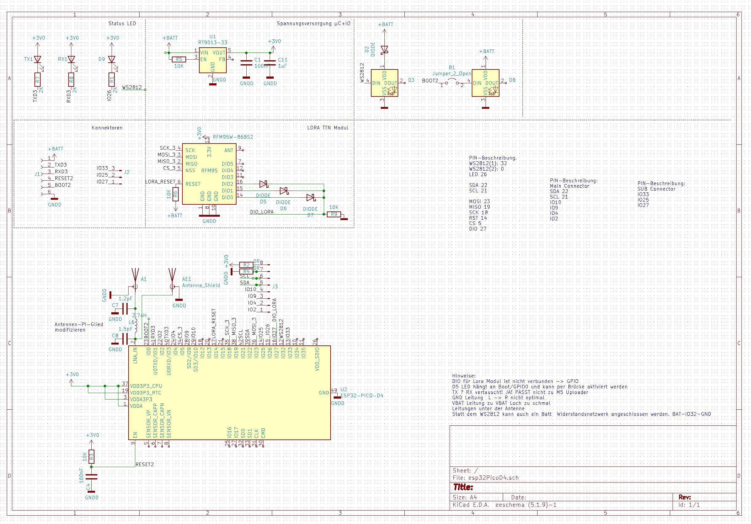
Power Supply:
a Low Drop out Voltage Regulator: I choosed the RT9013 It can drive up to 500mA on the 3.3 V Output and you can supply it with a maximum Power input of 6V. Perfect for USB or Lipo Power Supply
LORA Module:
The RFM95 is a prebuild LORA WAN 868 MHz Module that can establish a Longe Range LORA connection.
You can achieve up to 15km of range with this Radio chip. That is really crazy. We are gonna use this later on for location detection.
In my Area Stuttgart Germeny we have a public Lora Thethingsnetwork sponsored by the City Council. This gives me the opportunity to use this network for free.
The LEDS - SK6812 WW
You may have guessed it: But you are Wrong: No I am not using WS2812B RGB LEDS.
The reason is there is a nice competitor on the market. Called SK6812WW: You have the same footprint but a seperate White channel. This might be useful for a torch Light Function later on.
I choosed two different light paths. So you can have a status light and a seperate Backlight on one Logic Board
A 8 Pin 2.54mm Connector.
This connector is useful for all kind of sensors. There are lots of sensors out there in the market that fit on these connectors.
I made 2 0Ohm Resistors on Pin1 and Pin2 so you can easily switch orientation of 3.3V and GND. Some Boards differ on
A 3 Pin Connector with Special pins
I routed a three Pin Connector with some special pins extra on a connector. Watch espcialy Pin 25. This is connector to the DAC of The EP32 board. This gives you the chance to output some audio. This might be useful if you want to playback some sound
A Flash Soldering Connector
I am using on all my projects a USB to UART Programmer from M5 Stack. This tool is easy an so convieient
Discussions
Become a Hackaday.io Member
Create an account to leave a comment. Already have an account? Log In.