 doctek
Hardware
Have a look at the Hardware Overview diagram.
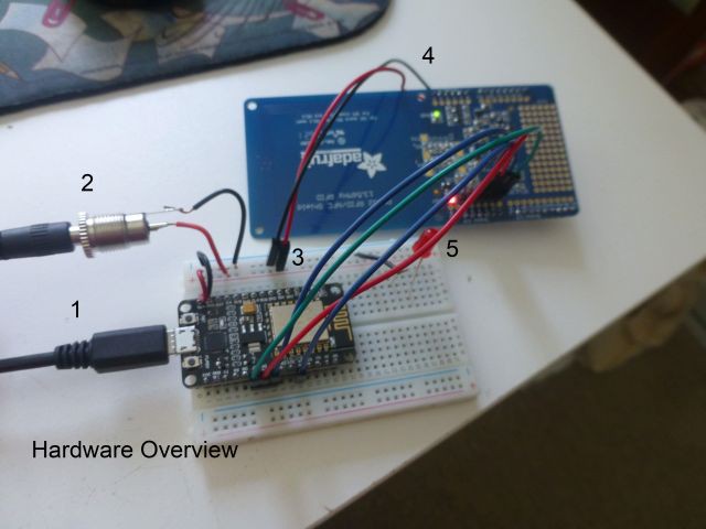
Here are the details that go with the numbers.
1. USB is used to program the NodeMCU, but I was unable to power it with USB.
2. The NodeMCU schematic (included in the Files section) shows that there is a protection diode so it's OK to hook up an external 5V power supply. Be sure that your supply actually puts out 5V +/- 5%. Higher values can be handled by the regulators on the boards, but could damage the USB port on your PC. I used a 2 amp supply, but 1 amp would probably do.
3. Connect the external 5V to the PN532.
4. Connect 5V and GND to the corresponding Arduino pins. These are clearly marked on the PN532 board.
5. Details of the SPI connection are shown in the next two photos.
SPI for the NodeMCU is connected as shown here.
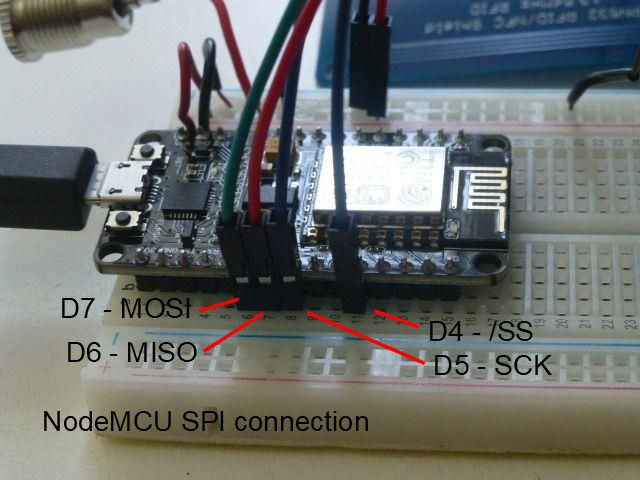
The four SPI pins we need are SCK, MOSI, MISO, and /SS. SCK (GPIO / D5) is the clock signal, MOSI (GPIO / D7) and MISO (GPIO / D6) are the data lines, and /SS (GPIO2 / D4)is the active-low select line. While the /SS line can supposedly come from any NodeMCU GPIO, I found that using GPIO15 / D8 caused problems. Using it, the NodeMCU would hang on reset and could not be programmed until the line was disconnected. It then had to be reconnected to make the PN532 read again. Using GPIO2 / D4 avoids both these problems. A pinout diagram is included in the Files section.
The PN532 has an area marked for connecting the SPI bus.
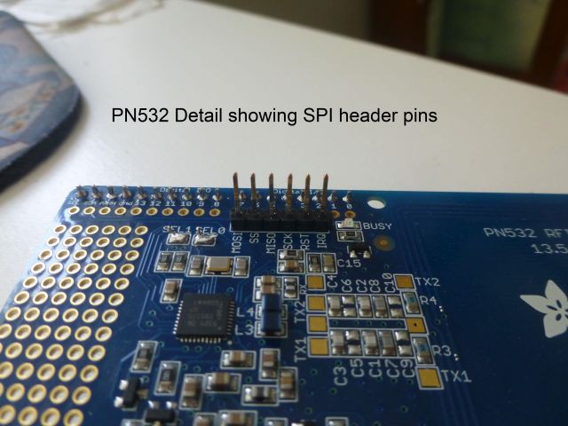
I soldered gold square pins into the board as shown to allow easy connection to the SPI bus. The names on the board correspond to the names used above. While it may be temptng to swap MISO and MOSI, resist that temptation! Connect MOSI from the NodeMCU directly to MOSI on the PN532. Same for MISO.
Also notice that there is no need to do any level-shifting of the SPI signals between the NodeMCU and the PN532. The PN532 shield includes the necessary interfacing and the NodeMCU reacts perfectly. No need for any extra circuitry.
Software
If you haven't already done so, install the NodeMCU/ESP8266 board. Use Tools -> Board -> Board Manager and scroll down to esp8266 by ESP8266 Community version 3.02 and install it. You should now be able to select NodeMCU 1.0 (ESP 12E module). This will make sure the ESP8266 SPI library is used.
Install the PN532 library from Adafruit. Use Tools -> Manage Libraries and locate Adafruit PN532. Install version 1.2.2. You'll be prompted to install Adafruit_BusIO library as well (version 1.9.0). Do that, it includes the Adafruit SPI library interface that is used with the PN532.
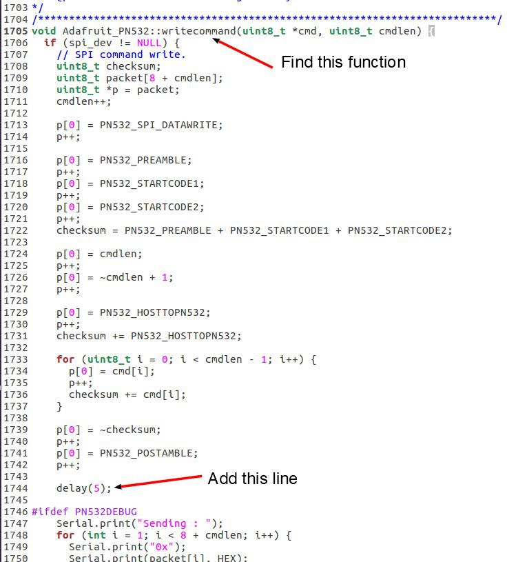
I selected the sketch from Examples -> AdafruitPn532 -> readMifareClassic. Very few modifications are required to make this sketch work. The define for PN532_SS was changed to 2 (GPIO2 is labeled D4 on the NodeMCU). The other defined pins aren't used and don't matter. Next comment out the line for a SPI connection, and uncomment the line for a hardware SPI connection. That should be all that's required to make the reader work. But it's not. There is a timing problem that requires a library modification. It's necessary to do a small modification to the Adafruit PN532 library.
Find your sketchbook by looking in File -> Preferences and go to that location. Now find the libraries directory and the file Adafruit_PN532/Adafruit_PN532.cpp in that directory. This is the file you need to modify. This figure shows exactly what to do. Be sure to save the file in the original location when you've edited it.
With the library edited, compile and download to a system hooked up as described above. Monitor execution with the Serial Monitor. Your code should halt waiting for a card, and run continuously when a card is placed on the reader. A useful extension would be to look at the card ID and do an action if the correct card is read. If you have any problem, my working code is in the Files section as ESP8266_readMifareClassic.ico.
ConclusionSee? I told you it was ridiculously simple! It just took a while to sift through all the information...
Read more »
 Paul Andrews
 Ken Yap
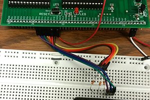
 Bruce Land
 Dave Vandenbout
i replicated the exact connection design, made sure that the library is edited and updated, I still get cannot find the PN5XX, also will the Node MCU power on from the 5v connection ? My NodeMCU only turns on when i connect it via usb.