 Guillermo Perez Guillen
A proportional–integral–derivative controller (PID controller) is a control loop mechanism employing feedback that is widely used in industrial control systems and a variety of other applications requiring continuously modulated control. A PID controller continuously calculates an error value e(t) as the difference between a desired set point (SP) and a measured process variable (PV) and applies a correction based on proportional, integral, and derivative terms (denoted P, I, and D respectively). https://en.wikipedia.org/wiki/PID_controller
In my case I used "PID Example By Lowell Cady" to simulate the behavior of the PID controller and in the figure below you can see the graph, which has a stable behavior as time goes by: https://www.codeproject.com/Articles/36459/PID-process-control-a-Cruise-Control-example
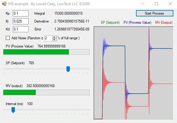
PID controller simulation
The Autonomous robot is equipped with 3 analog infrared sensors, which detect the distance at which the walls are, one in front and two on the left and right sides. To calibrate the distances of the infrared sensors GP2Y0A41SK0F and GP2Y0A51SK0F, you can see the post and my code below: https://www.instructables.com/id/How-to-Use-the-Sharp-IR-Sensor-GP2Y0A41SK0F-Arduin/
float ir_sensor_left =  6*pow(volts0, -1); // worked out from datasheet graph //GP2Y0A51SK0F - 2 a 15 cm
float ir_sensor_center = 12.4*pow(volts1, -1); // worked out from datasheet graph //GP2Y0A41SK0F - 4 a 30 cm
float ir_sensor_right = 5.2*pow(volts2, -1); // worked out from datasheet graph //GP2Y0A51SK0F - 2 a 15 cm
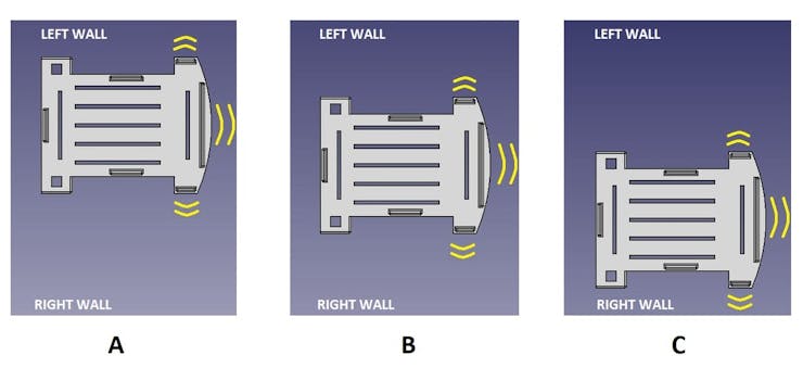
Also the autonomous robot is equipped with 2 ultrasound sensors: 1) The HC-SR04 is on the left side and oriented in the direction of 45 degrees; and 2) SRF05 is on the right hand side and oriented 45 degrees. Thus we use the two GP2Y0A51SK0F sensors to control the speed of the Autonomous Robot. The robot uses PID controller to maintain a central distance between the left and right walls. If the robot is near the left wall, then it can decrease the speed of the right motor and increase the speed of the left motor, to make the robot move to the right, and moving away from the left wall, and vice versa.
PID Controller
The speeds d0 of the left engine and d1 of the right engine are calculated with the following code:
dif = analogRead(A3) - analogRead(A0);    // PID CONTROLLER
error = floor(Kp*(dif)+Kd*(difAnt-dif));    // PID CONTROLLER
difAnt=dif;    // PID CONTROLLER
int d0 = constrain(150 - error, 0, 150);//left speed - PID CONTROLLER
int d1 = constrain(150 + error, 0, 150);//right speed - PID CONTROLLER
However, the robot's movement may be unstable due to the error caused by a small time error, we have added a second correction factor to make the movement smoother. That is to say: difAnt= dif; now the speeds are applied by means of PWM signals to the two gearmotors:
analogWrite(ENA, d0);
  analogWrite(ENB, d1);
  digitalWrite(IN1, out1 * HIGH);
  digitalWrite(IN2, out2 * HIGH);
  digitalWrite(IN3, out3 * HIGH);
  digitalWrite(IN4, out4 * HIGH);
  delay(20);

Discussions
Become a Hackaday.io Member
Create an account to leave a comment. Already have an account? Log In.