 Ted Yapo
The PCBs for the flash boards (and the pulse hubs) arrived last night, as did the DigiKey box with all the parts - that doesn't happen often enough :-) I found some time to assemble and start testing one of the flash boards today. The back view shows the aluminum polymer caps:
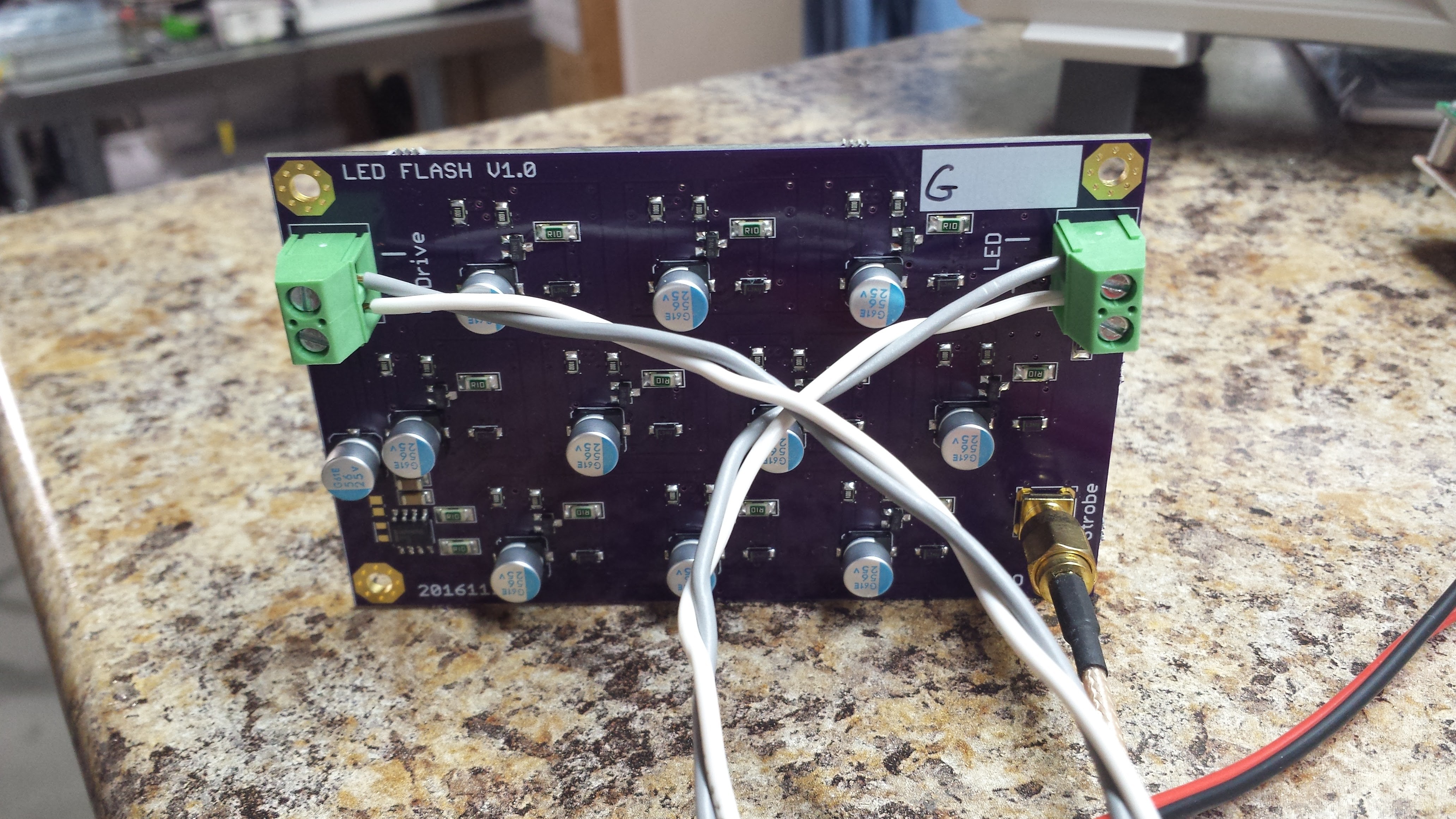
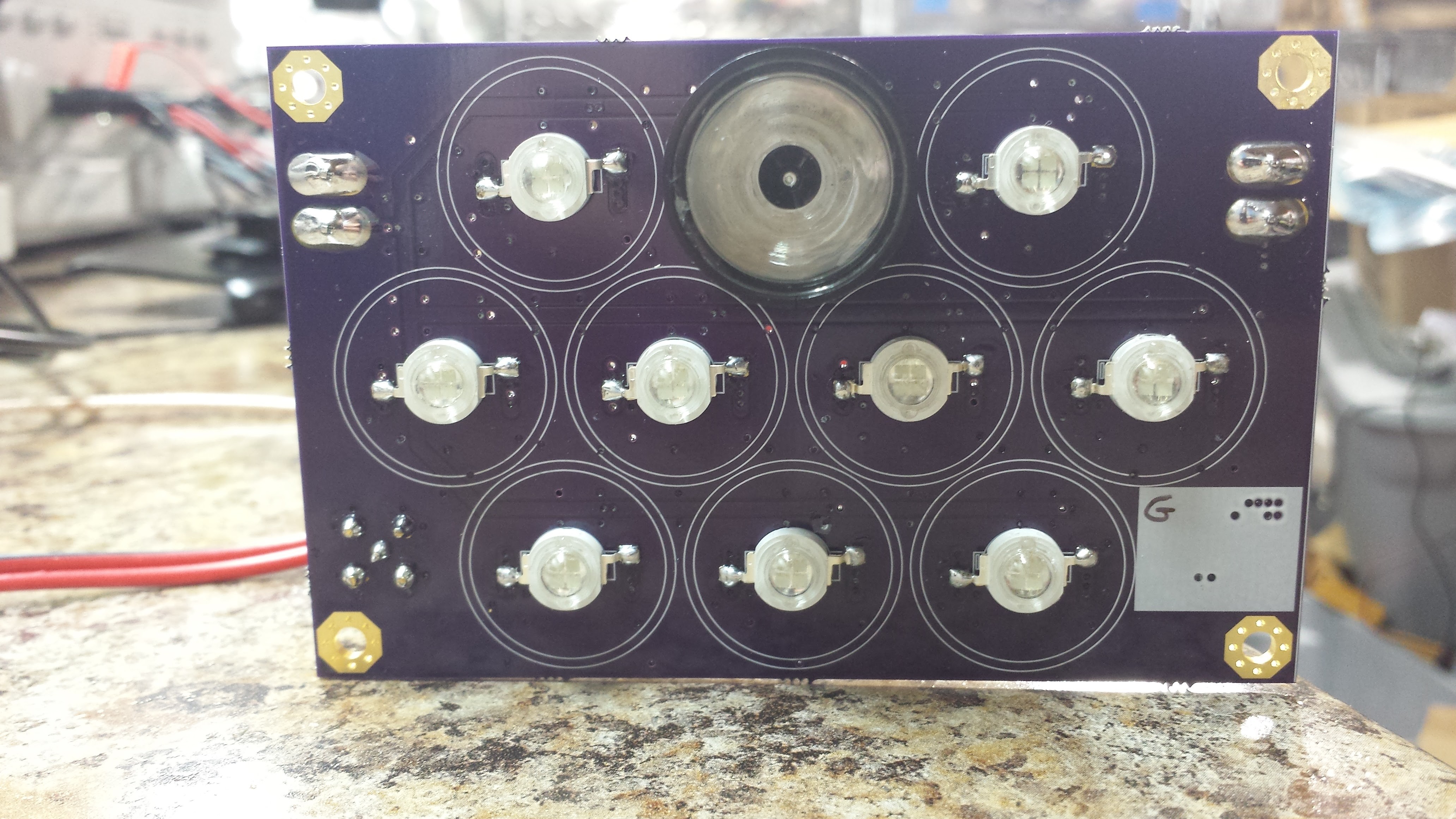
The screw terminals are "backwards" so I can mount these boards in a tight grid (R, G, B) with possibly more than one board per color. The front of the board shows the LEDs, 4-chip "5W" packages, as well as a single lens/reflector I was testing:
All the components on the back were reflow soldered on the skillet, then the LEDs and connectors were soldered on manually. The board seems to work as designed, with the exception of the footprint for the SMA connector - the corner mounting holes are too small.
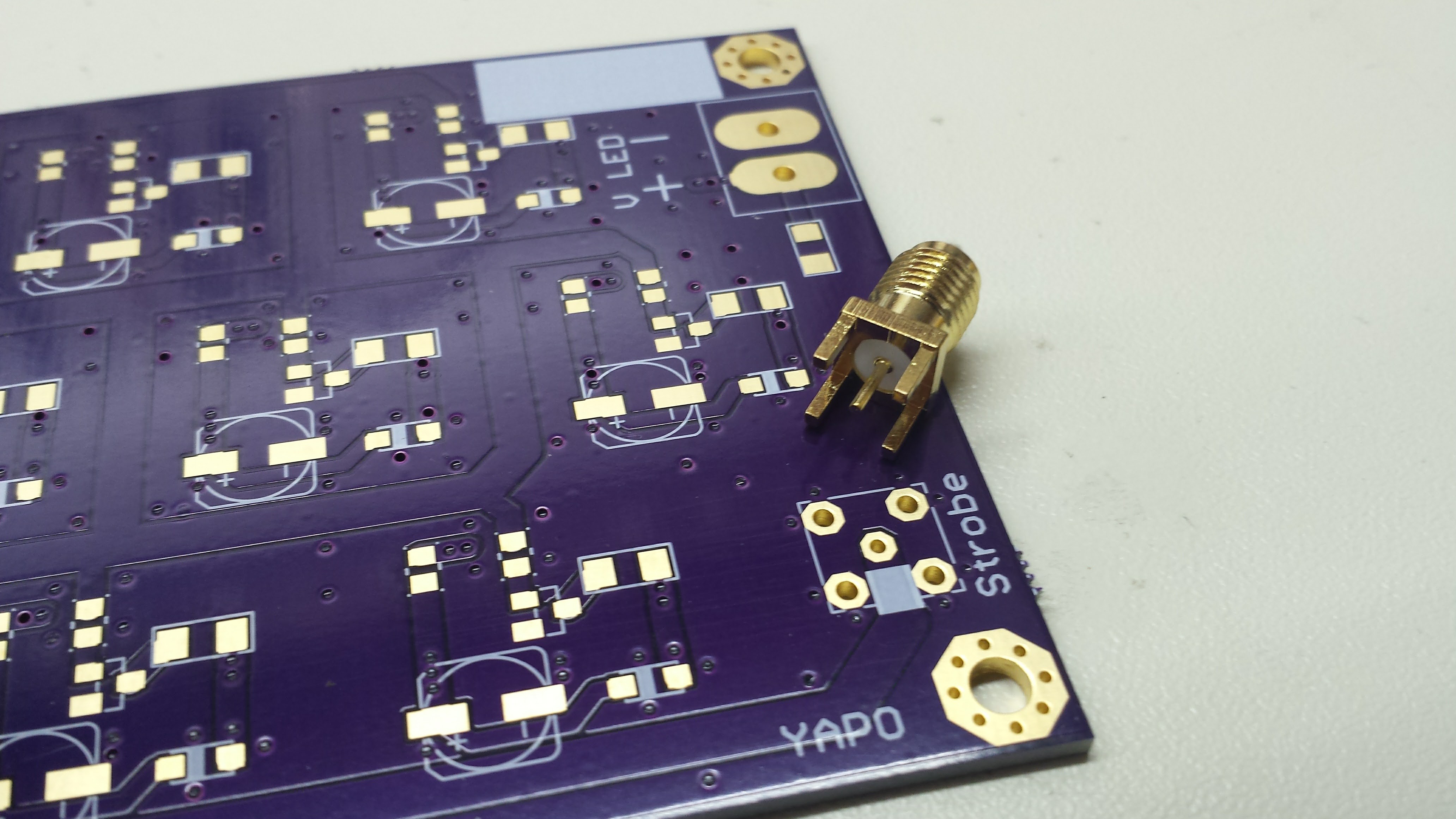
I don't know how I screwed this up - the square root of 2 is still around 1.414, right?? Anyway, rather than drill out the nice plated-though holes, I filed down the connector to make it fit.
Measurements
I tested the board at a number of different LED voltages - the flash controller board will have software-adjustable regulators for setting these, since the different color LEDs have different forward voltages, and the red LEDs appear to all be in parallel in the package, instead of the series/parallel arrangement of the green and blue.
Here's the waveform across the 0.1-ohm resistor in series with one of the LEDs:

The voltage is measured across a 0.1-ohm resistor with a 2x Z0 probe, so this pulse represents 14.9A of current through one of the 10 LEDs. The supply voltage was 18.5V for this pulse - the capacitors are rated 25V, so I could go somewhat higher. Since the LEDs are rated for 700 mA, this represents about a 21x overdrive. After several hundred pulses, I couldn't detect any changes in the LEDs, but obviously I need to test it a lot more.
Design
The nice shape of the waveform and minimal ringing is due in large part to some design hints I got from others here.
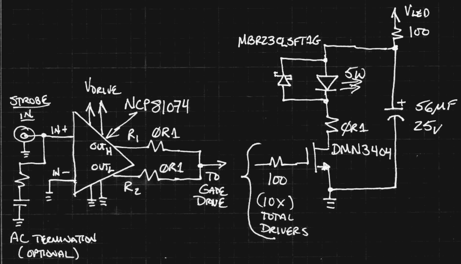
The NCP81074 10A MOSFET gate driver was completely over-sized for a single MOSFET, but does well driving 10 of them. A 100-ohm resistor at each gate keeps the edges relatively slow preventing overshoot and ringing. The 2A Schottky diode across the LED protects it against the brief reverse-bias overshoot on the trailing edge. I included sites for AC-terminating the 50-ohm input, but haven't populated them. I'm going to drive the board from series-terminated sources, so I don't expect a problem, but they're there if needed. Bypass caps aren't shown.
I included the R1 and R2 resistors right at the output of the driver in case series terminations were required to tame reflections on the gate drive line. The driver has edges of a few nanoseconds, and you can see a light ring/reflection after about a quarter of the rise time of the pulse above. I suspect the inductance of the long, branching gate drive trace on the PCB is to blame. I actually populated R1 and R2 with 0.1 ohm R's, so I can probe them and have a look at what's going on. Resistors of maybe 10 ohms there might help eliminate that one annoying ring. When I get a chance, I'll post a better scope trace of the offending ripple.
Overall, this board looks like a success. It's bigger with less light output than I originally imagined, but seems pretty manageable and scalable - I can just use as many as I need. Next, I'll figure out which lenses make sense for a useful beam angle, and I can take some test photos.
I've been working on a photogate design, too. I'll document that soon.
EDIT - I just did the math. Assuming the forward voltage of the LEDs is around 10V at this current (probably conservative), the pulses dump about 1500W of power into the LEDs.
Discussions
Become a Hackaday.io Member
Create an account to leave a comment. Already have an account? Log In.