 Ted Yapo
Block Diagram
Here's the big-picture design for the system. I'm envisioning a trigger/timer/controller board and separate LED flash driver boards to ease staging the photographs. The controller will look something like this:

I'm not sure which PIC I'll end up using: for this application, it doesn't seem to matter that much. I have a 18.432 MHz xtal drawn in because that's what I had available for prototyping. This allows a 217ns code timing resolution, which is plenty fine enough, and also keeps the UART baud rates exactly on spec - maybe I'll stick with this frequency. Using 5 instruction cycles for an LED pulse results in 1.08 us.
The timing function is triggered by one or both photogates (amplifier and comparator design TBD). These can sense a milk drop or rifle projectile in flight. Using both gates with a known spacing allows the projectile velocity to be determined. I have also thought about a sound-based trigger, which I will probably experiment with a little.
The UART lines run (through a USB-UART bridge) to a PC where timing parameters can be downloaded to the system.
I'm not sure what connectors to use for the LED voltage ports yet. Maybe banana jacks, since they're all DC.
VLED Regulators
Since the R, G, and B LEDs have different forward voltages and different brightnesses, a variable voltage source will be provided for each color (the 'ADJ REG" blocks above). These can be tuned to balance the flash brightnesses, and accommodate different flash driver circuits.

A cheap 10-bit DAC drives a cheap linear regulator through a level-shifting op-amp. I've used this type of circuit before, and it works well for a digitally-controlled voltage source. The LM317 only works up to 36V, so if I need more than that, I'll have to look for a different regulator. I'd like to stick with integrated solutions, here, though. The combination of thermal and over-current limiting built into these things is hard to beat.
The PIC controls the 3 DACs through SPI.
Cable Drivers
I am a sucker for double-terminating cables. Although you could get good waveforms with a simple back-termination here, I'm adding the receiver terminations, too, for noise immunity. With maybe a hundred amps switching in neighboring LED channels, I don't want accidental triggers - the 50 ohm termination may help somewhat.
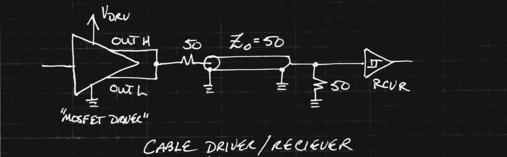
Since I'm going to be using integrated MOSFET gate drivers for the flash circuits, I figured I'd use them as cable drivers, too. They seem perfect for the job - fast edges, a controllable voltage level, and plenty of current drive. The problem with double-termination is that it cuts your signal in half, but with these drivers, you can just set Vdrv to twice the desired swing to compensate.
I initially made some prototypes with NCP81074 drivers from ON Semiconductor. These work great, but I can only find the "B" variety in stock - they have an input threshold set to one half the driver voltage. The "A" variety have fixed-level logic thresholds, but are nowhere to be found. I'd ideally like to have both available - the logic threshold version for the cable driver (which gets driven from the PIC), and the 1/2 Vdd version for the receiver (for noise immunity). I ordered some Microchip MCP1406's, which are a little slower, but still fine for this application. I can use the Microchip parts for the logic-threshold cable drivers and the ON Semi parts for the receivers / MOSFET drivers (their intended use!) on the flash board(s).
Discussions
Become a Hackaday.io Member
Create an account to leave a comment. Already have an account? Log In.