 Ted Yapo
Where's the first one, you ask? I'll write it up in a bit: a log of how reality sometimes clashes with your understanding of the world (it didn't work too well). In any case, the second one demonstrates the principles, although it will need scaling up to provide enough light for good images. Here's the assembly:
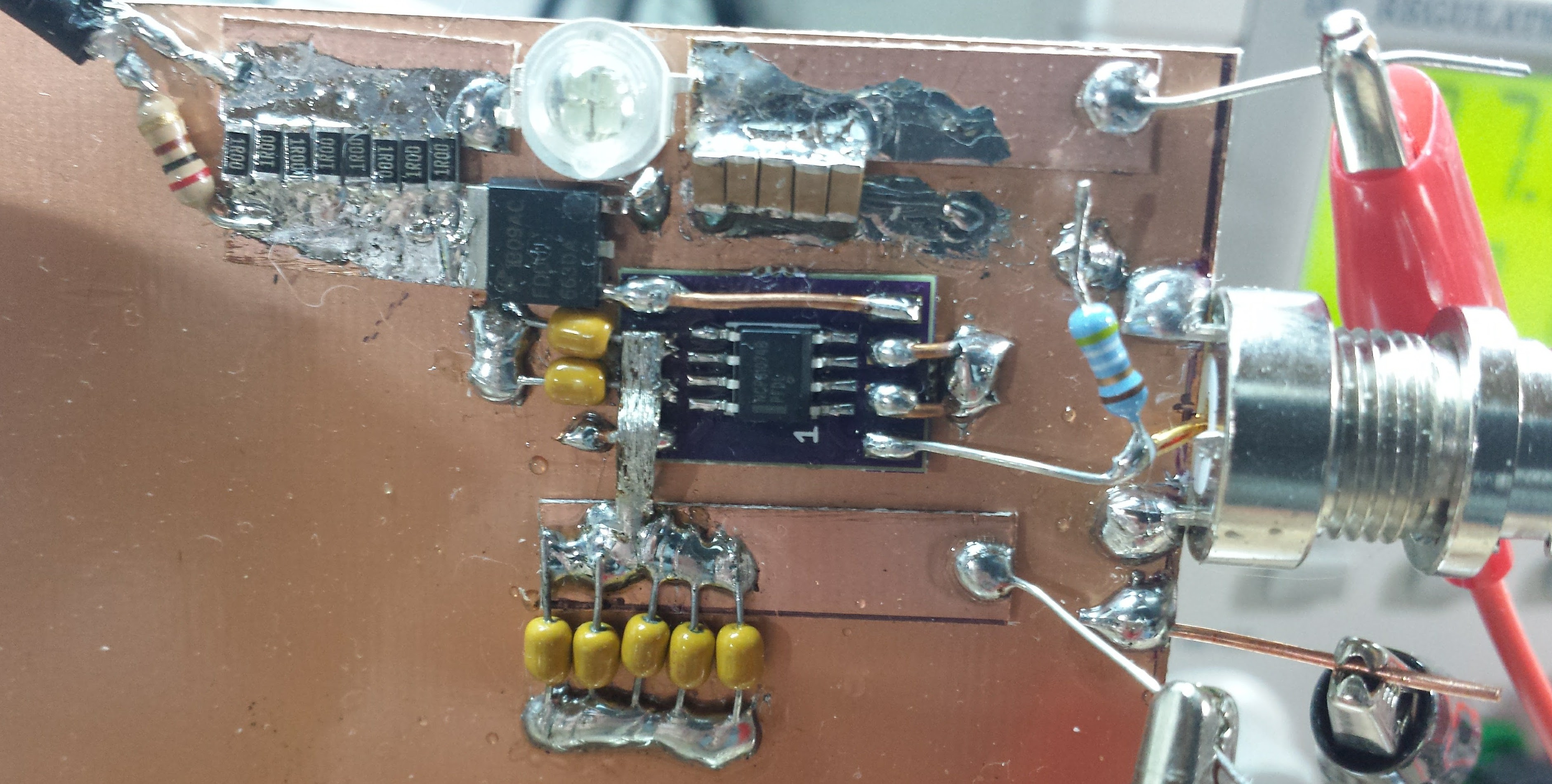
and the schematic:
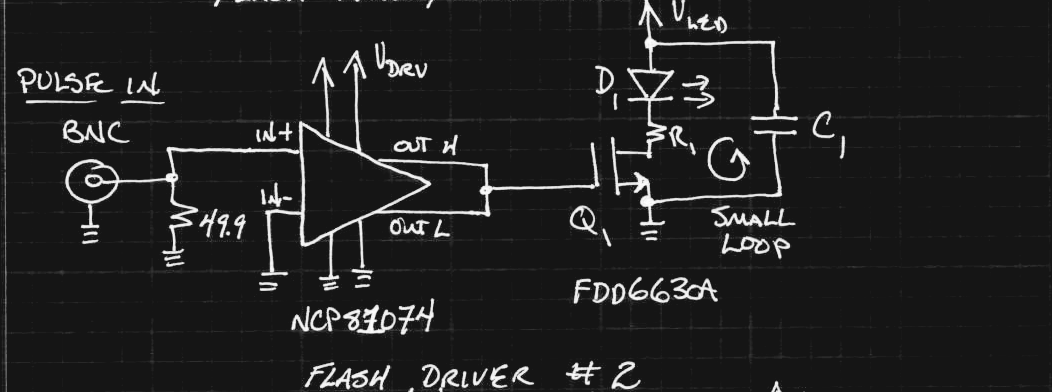
I built this one when I only had the MLCC capacitors available, so I used five of them in parallel (upper right on the board) for C1. The yellow caps are bypass for the MOSFET driver voltage. I also didn't have any low-valued resistors for R1, so I paralleled 8 1-ohm ones for a resulting 125 milliohm. This helps ballast the LEDs against temperature effects, and provides a convenient place to sense the current. The NCP81074 MOSFET driver serves double duty here as a line receiver and gate driver, while the FDD6630A MOSFET switches the current. You can see the layout allows the current to flow in a small loop through C1, D1, R1, Q1, and back to C1. The LED is a Chanzon "5W" green led that has four 30x30 mil chips connected in series/parallel.
Prototype Controller
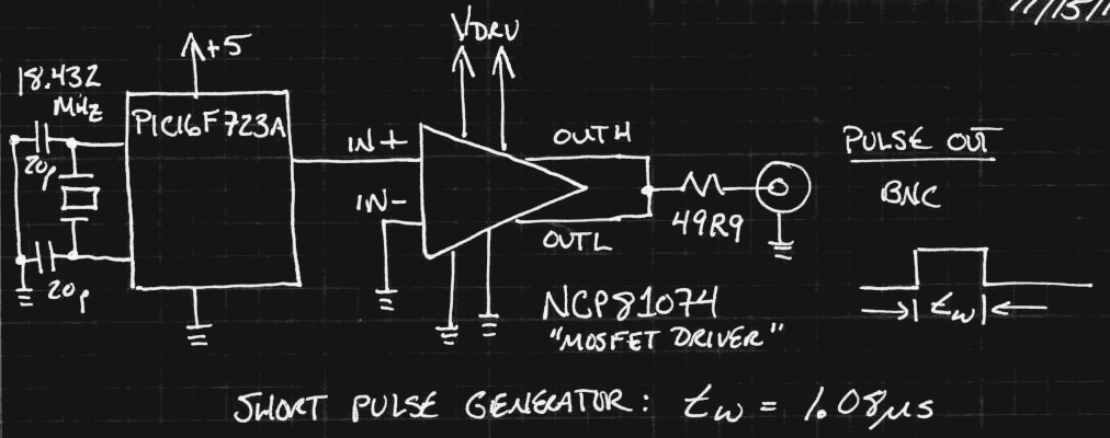
I drove the input with a quick prototype of the controller - a PIC16F723A generating 1.08 us pulses every second or so. I had a few breakout-type boards made for this processor at one point since I had used them in a few projects:
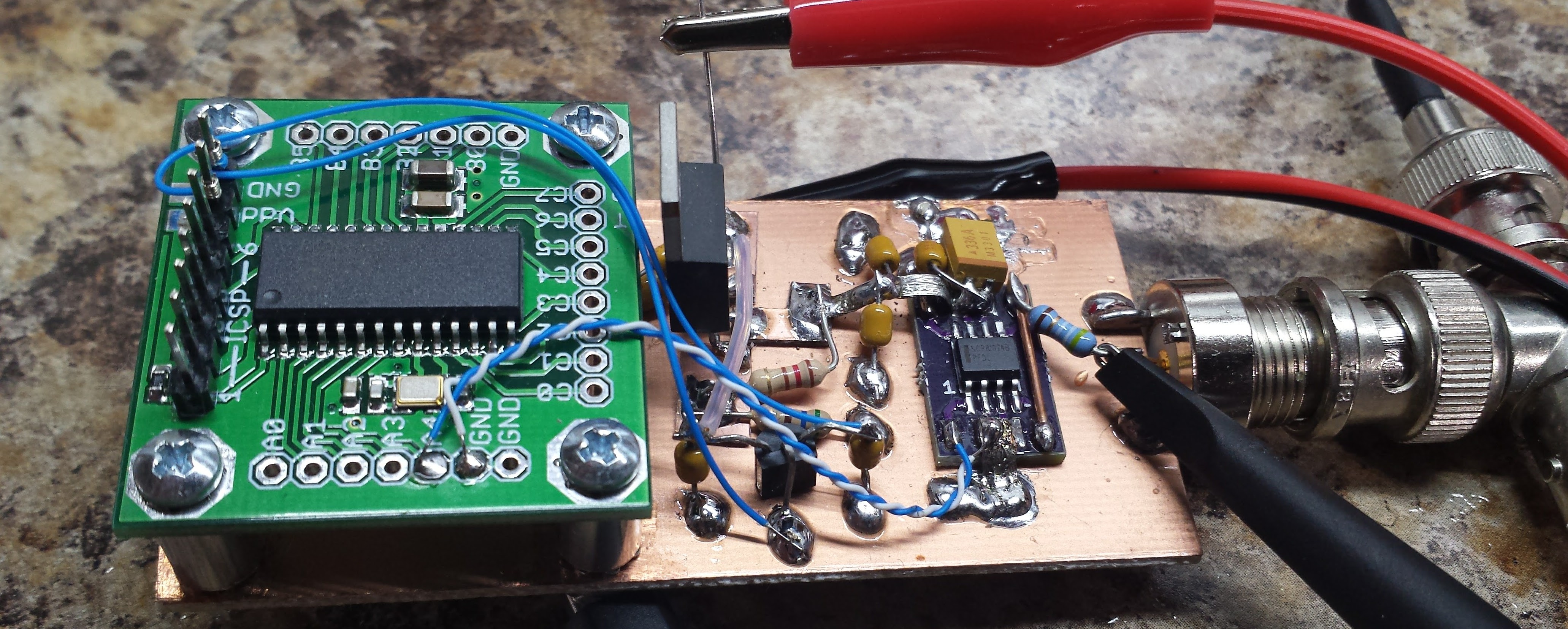
The cable driver is another NCP81074, as shown here:
![]() Measurements
Measurements
 Measurements
I used a battery-powered "floating" oscilloscope to probe the current through R1 in the flash circuit. I keep an otherwise "just OK" Owon SDS7102 around because it runs off batteries and can be connected between any two points in a circuit like this. I simultaneously measured the light output of the LED chips with the biased photodiode probe discussed in the previous logs. Here are the traces using a 24V supply for the LED voltage:
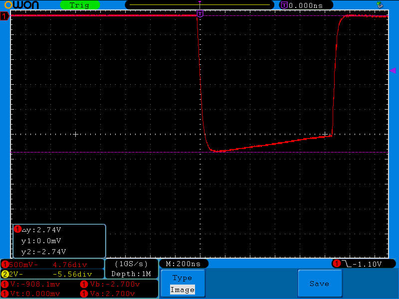
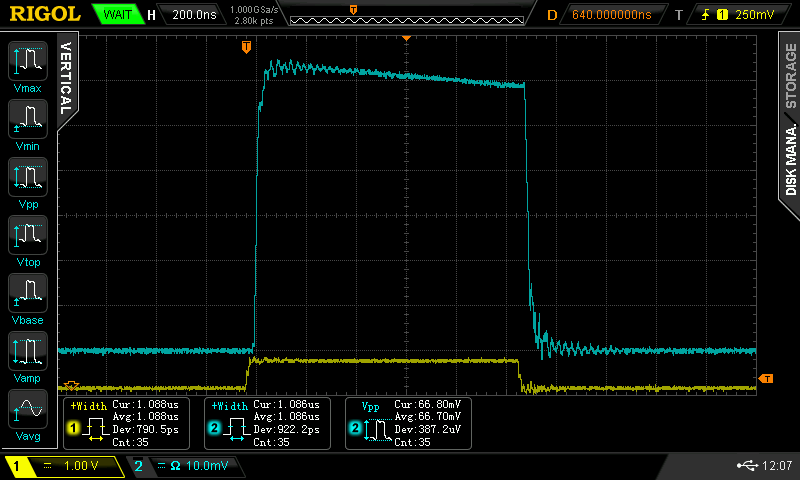
The 2.74V peak across the 125 milliohm R1 equates to about 22A of current through the LED chips, or about 11A for each paralleled string of two. The current pulse looks "negative" because of the way I soldered the probe onto the board :-) The detected light pulse (cyan) is shown along with the driving pulse from the PIC (yellow) on the other scope. The original electrical and detected optical pulse widths are essentially identical (measured 1.088 vs 1.086 us) despite the cyan somehow appearing longer.
I thought there were two interesting things in these measurements. First, the "50 uF" of capacitance looks like a smaller value according to how much the current droops during the pulse. That was expected for MLCC's, anyway. The shape of the detected light pulse is also roughly the same as that of the current pulse. This means that the LED is still operating in a monotonic mode (more current -> more light). I read a whitepaper that said at some point, the LED can stop outputting more light with added current. In the high current regime, we're way above the most efficient operating point of the LEDs anyway, but it makes absolutely no sense to use more current for no added illumination.
Next Steps
This circuit could go higher (the MOSFET is rated at 30V), except the capacitors are rated at 25V. The next step is to build another prototype with more suitable parts and more LED chips and see how it works.
I know this small prototype doesn't deliver anywhere near the light I need, but it would be interesting to see exactly how many of these 1 us pulses I need for a decent exposure with the camera. That would give me a solid feel for how much I need to scale things up.
Discussions
Become a Hackaday.io Member
Create an account to leave a comment. Already have an account? Log In.
If you want to reach high speeds, deadbug style can work but you need to reduce your loops' circumferences. The decoupling capacitors should be located over the driver, instead of going away from it...
Are you sure? yes | no
Yes, that's a good point. It would make sense to put the caps over this part - I would probably cut the loop in half. I wouldn't normally think of it, because I like to keep all the pins exposed and probe-able, but in this case, it wouldn't hide anything.
Are you sure? yes | no
Then again, I keep thinking this is a "fast" circuit, but microsecond pulses aren't really that fast - light travels 300m in 1 us, so all the distances here are insignificant. Even the loop inductance isn't too important - a square wave with 1us "pulses" has a frequency of 500 kHz. Now think of the size of inductors you need for a medium-wave receiver (maybe crystal sets in your youth).
The real problem isn't the speed, it's getting enough light.
Are you sure? yes | no
It is not the distance - propagation delays, but rather inductance. That's where the *area* of the loops comes in. Larger areas means higher inductance. If you actually want to see 10A/4ns...
The decoupling cap should be across the power pin over the top of the gate driver (or under it in a layout) instead of off the sides which introduces unnecessary loop area. Height also increases the loop area, that's why serious work uses SMT parts and not leaded parts. :P
BTW I have been known to wire up one of the dual inverting gate driver e.g. TP2811 (with schmitt trigger input) as an oscillator and use diodes to get low duty cycle pulses to drive the 2nd driver.
Something like this:
The (high threshold) MOSFET is used as a transient load (shorting the supply). I control the current by very carefully trimming the power supply to the gate driver.
I get 50A/us pulses off for testing switch mode supply transient response - pretty much like the LED simulation. :)
Are you sure? yes | no
you forgot a tiny detail: it's not the frequency that counts but the edges ;-)
Are you sure? yes | no
True, but for these pulses, relatively slow edges would be fine. Xenon flashtube circuits have a long exponential tail, and they do OK.
Are you sure? yes | no
Why are the outputs OUTH and OUTL shorted ? is it a split output with separate high-side and low-side transistors ?
Are you sure? yes | no
The MOSFET driver lets you use different resistors to control gate rise time and fall time separately. I want them both as fast as possible, so I omitted the R's altogether.
In other words, yes, you got it!
Are you sure? yes | no
So what went wrong with the first proto ?
Are you sure? yes | no