Introduction
The ESP8266 ESP-01 is a great device for creating automation & electronics projects with the Internet of Things. In this article, you will get 5 free samples of this board and learn how to build the complete schematic of the electronic project.
This circuit board solves a big problem. See below!
See the ESP-01 printed circuit board presented below.
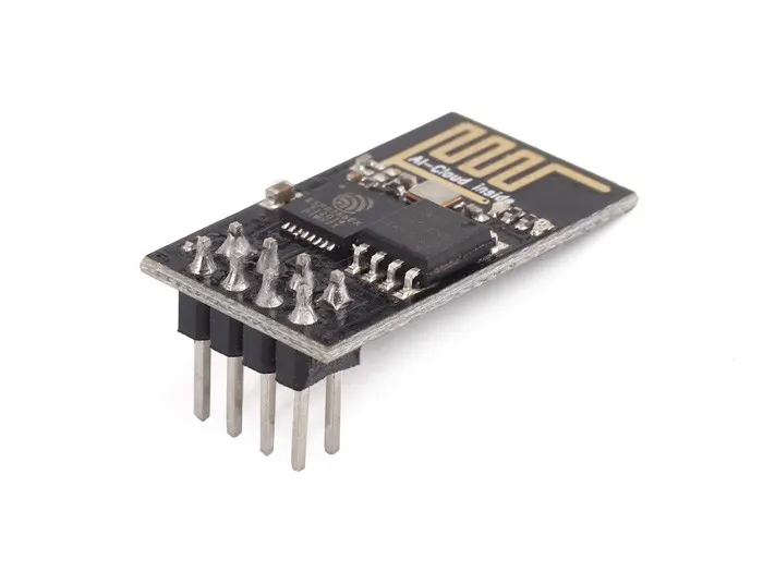
Figure 2 - ESP8266 ESP-01 Board.
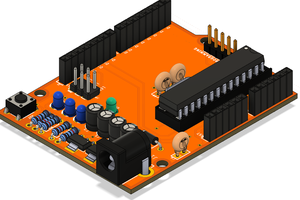
The ESP8266 ESP-01 requires an external circuit to transfer programming. This circuit consists of 2 buttons: Flash and RESET. See the image presented below.

Figure 1 - Shield ESP8266 ESP-01 Programmer.
Shields that are sold on the market do not have these buttons, and this makes it difficult to transfer code to the ESP8266 ESP-01 board.
To solve this problem, we have implemented code transfer buttons and other features to facilitate the creation of device control systems over the internet.
The ESP-01 is connected in socket 2x4 presented in our ESP-01 shield programmer.
Run away from this problem and get 5 free samples of this ESP8266 ESP-01 shield.
The Shield ESP8266 ESP-01 can be used for two purposes:
- Teaching Internet of Things with ESP8266 ESP-01;
- Develop automation solutions with IoT and ESP8266 ESP-01.
Do you want to earn your 5 samples? The process is simple.
How to get the 5 PCB free samples?
JLCPCB is supporting this article and makes 5 free samples of this PCB available for free. You can purchase through the step-by-step instructions shown below.
1 - Download the circuit board Gerber file: https://bit.ly/HomeFiBoard
2 - Create an account using the link below: https://www.jlcpcb.com/PFC
3 - Add the Gerber file and place the order. In the payment step, you must enter the JLC-REBE coupon to earn your 5 samples.
This coupon will free up to 5 free units without the components. You receive and assemble at your home!
Let's get started!
Shield ESP8266 ESP01 Programmer and Automation
Below we have the electronic schematic of the shield ESP8266 ESP-01 programmer. It was divided into 9 blocks.
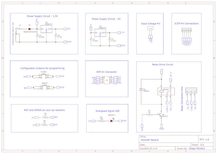
Figure 2 - Electronic Schematic of the Shield
Next, we will begin the discussion of each block in the shield circuit. Initially, we have the power input circuit through a jack connector. The input voltage for the project is from 7V to 9V.
Diode D1 is used to prevent polarity reversal of the source connected to the connector Jack.
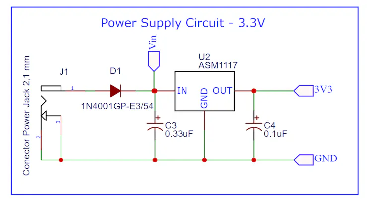
Figure 3 - AMS117 3V3 with input voltage of Jack Conector.
After the diode, the input voltage (Vin) is transmitted to the two voltage regulators of the circuit (AMS1117 3V3 and AMS1117 5V), and the pin header is presented below. The pin header is applied to offer Vin voltage for a protoboard.
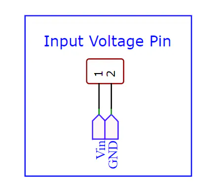
Figure 4 - Pin header to offer Vin voltade for protoboard circuit.
The voltage regulator capacitors were selected based on the indication of the AMS1117 IC datasheet.

Figure 5 - AMS117 5V.
These two voltage levels are used to power the ESP8266 ESP-01 (3V3) and drive the relay coil (5V).
In the circuit, we put an indicator LED to signalize that the circuit is powered, which is presented in the figure below.

Figure 6 - LED Indicator.
After that, we have the circuit to set the ESP8266 ESP-01 to programming and reset mode. This circuit is a big differential on this shield board.

Figure 7 - Circuit to program ESP8266 ESP-01 and reset the board.
Why is this circuit a great differential in our project?
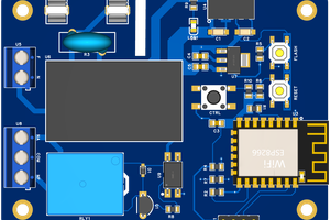
See the board shown in the figure below.

Figure 8 - ESP01 Programmer Shield.
This board is sold in several stores around the world, but it has a big problem. You need to solder the buttons to set the CHIP ESP8266 ESP-01 to programming mode.
Do you want to buy a card and change the structure when you receive it?
Certainly not! That's why we created our version.
Enjoy and earn your 5 free samples and assembly your own projects with the support of JLCPCB Company. You'll receive 5 PCBs! Register now!
1 - Download the circuit board Gerber file: ...
Read more »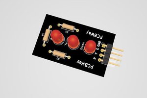
 Silícios Lab
 RachelAnne