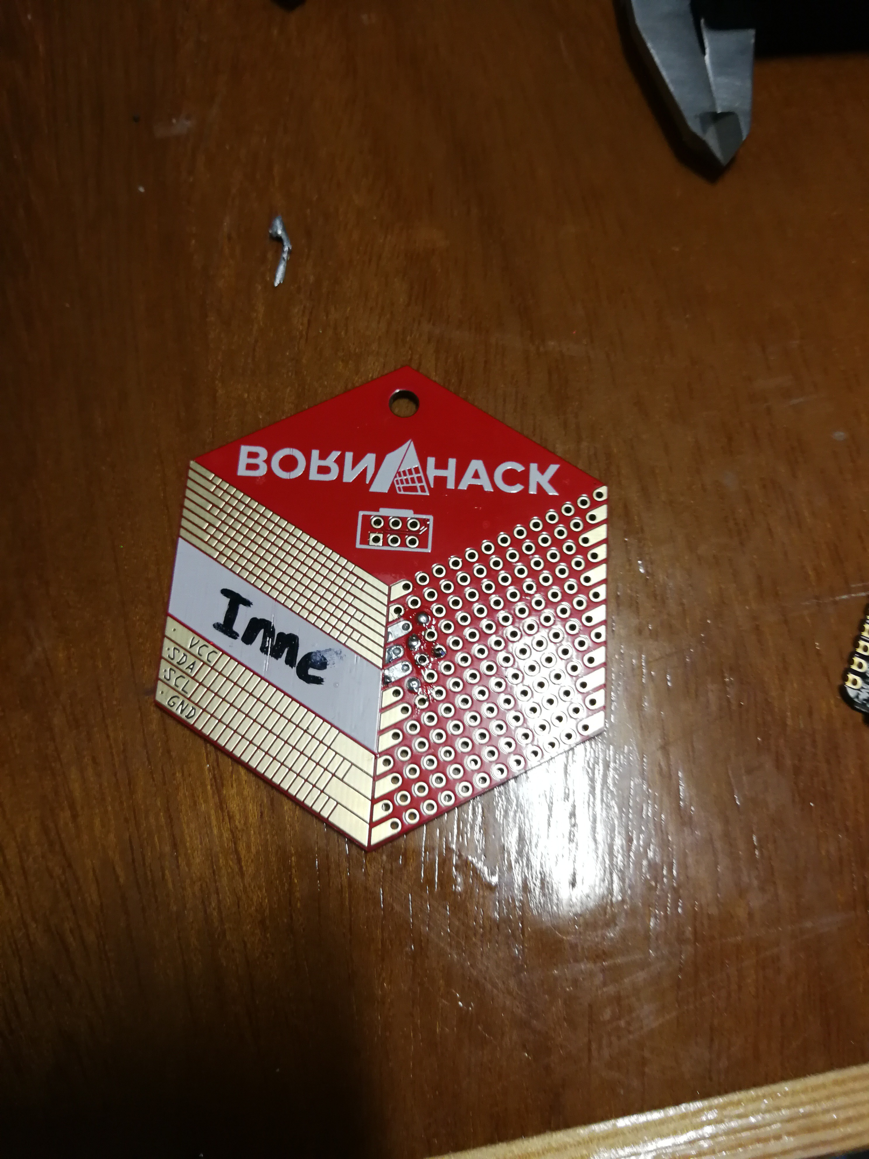
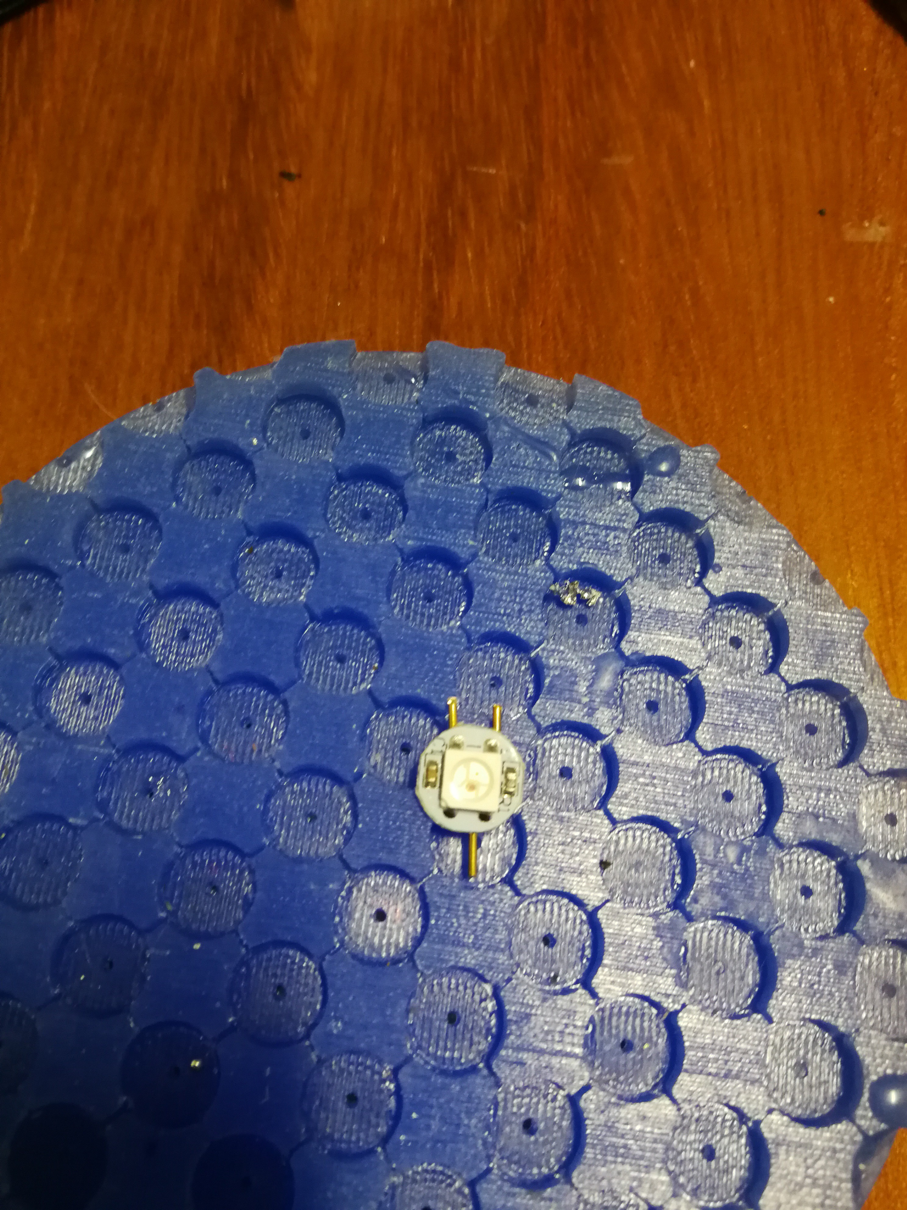
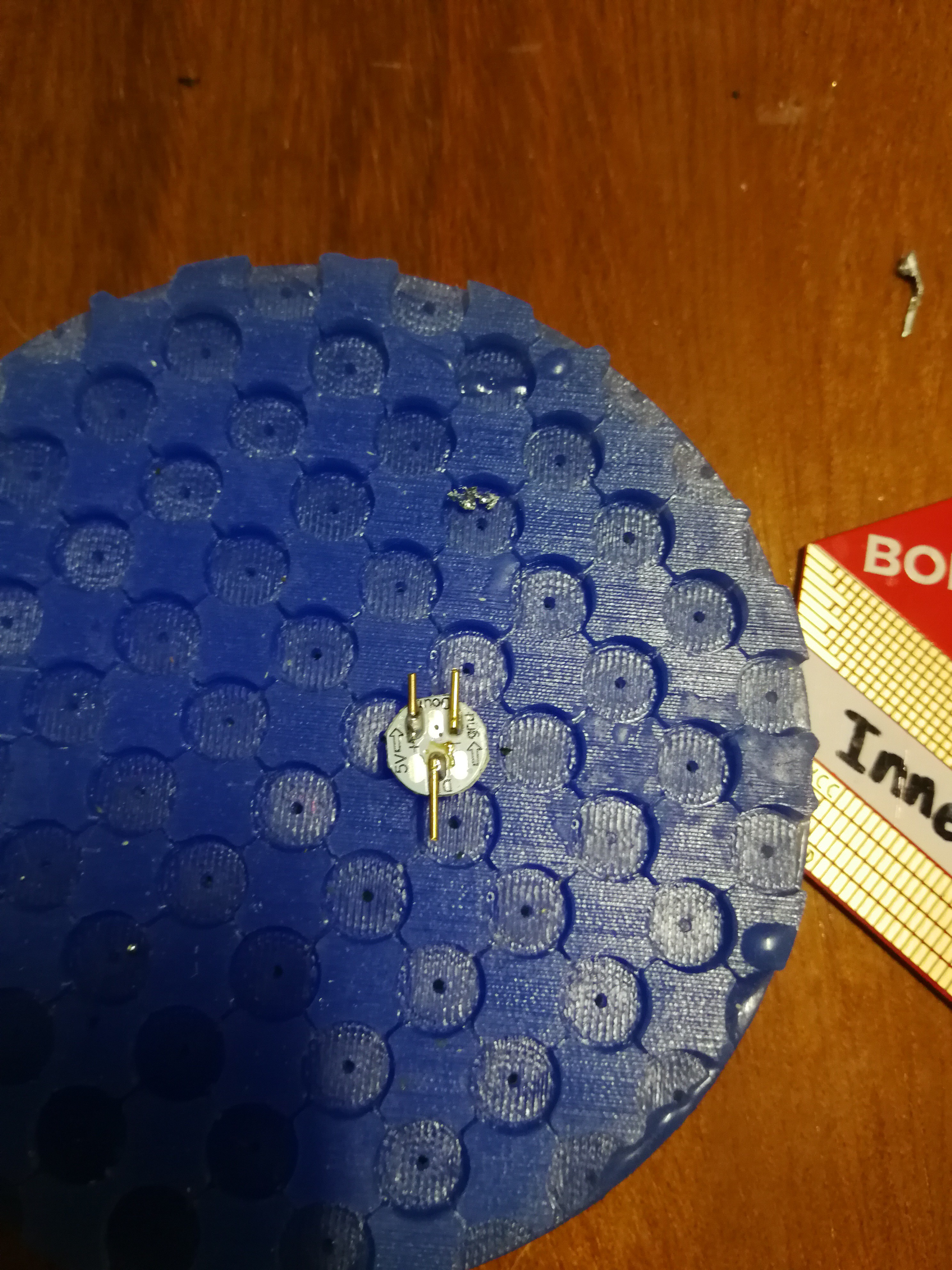
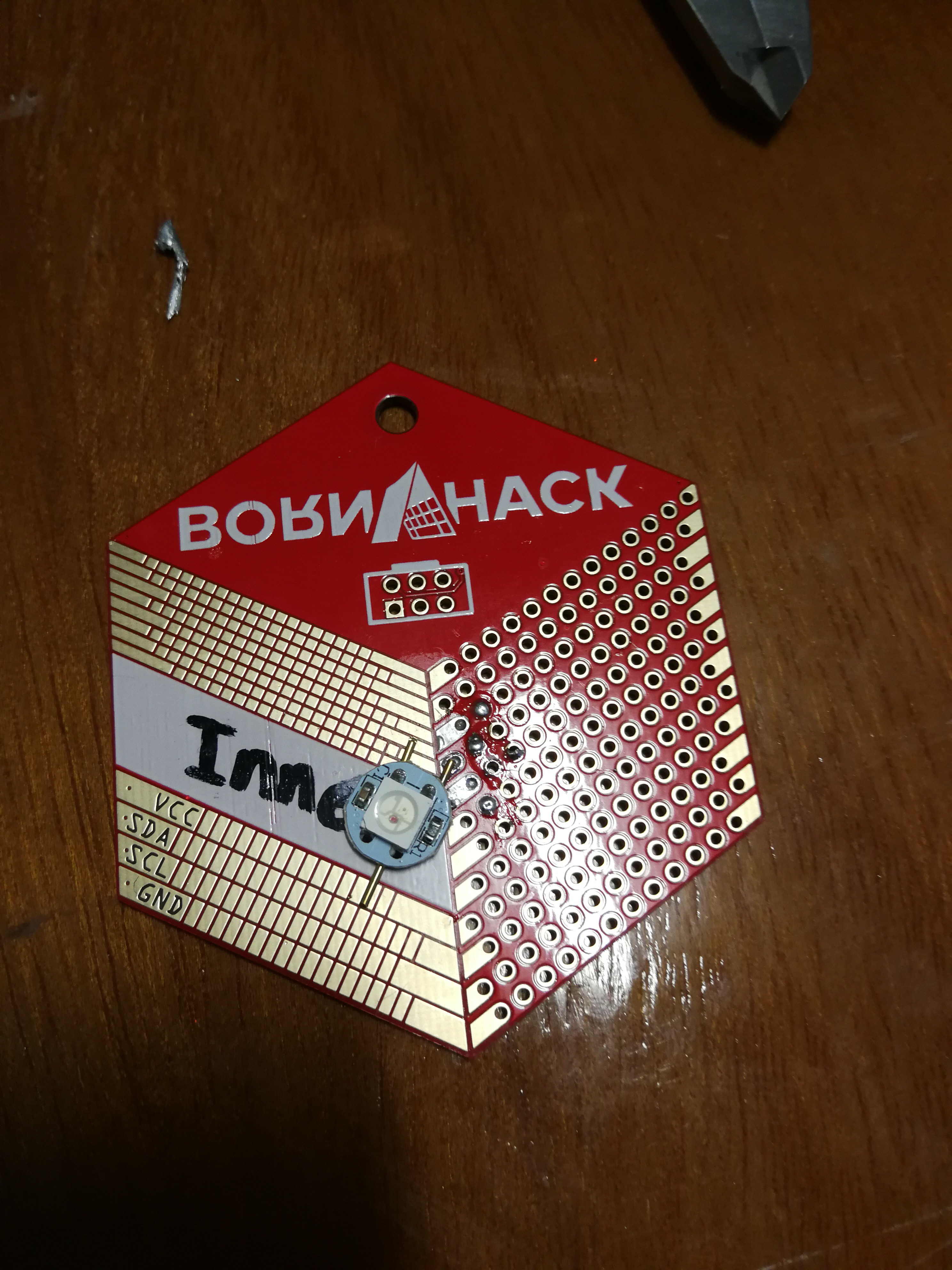
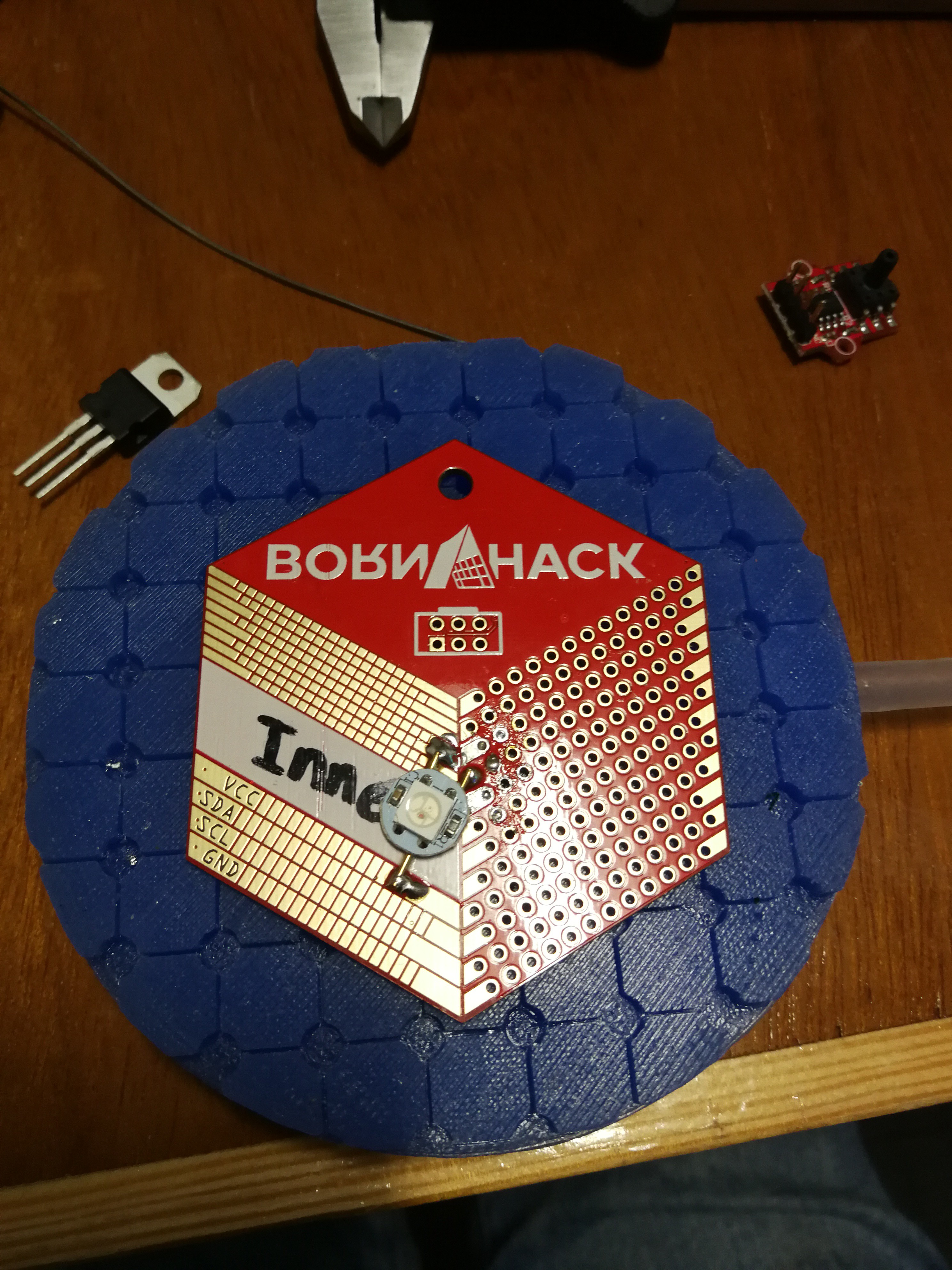
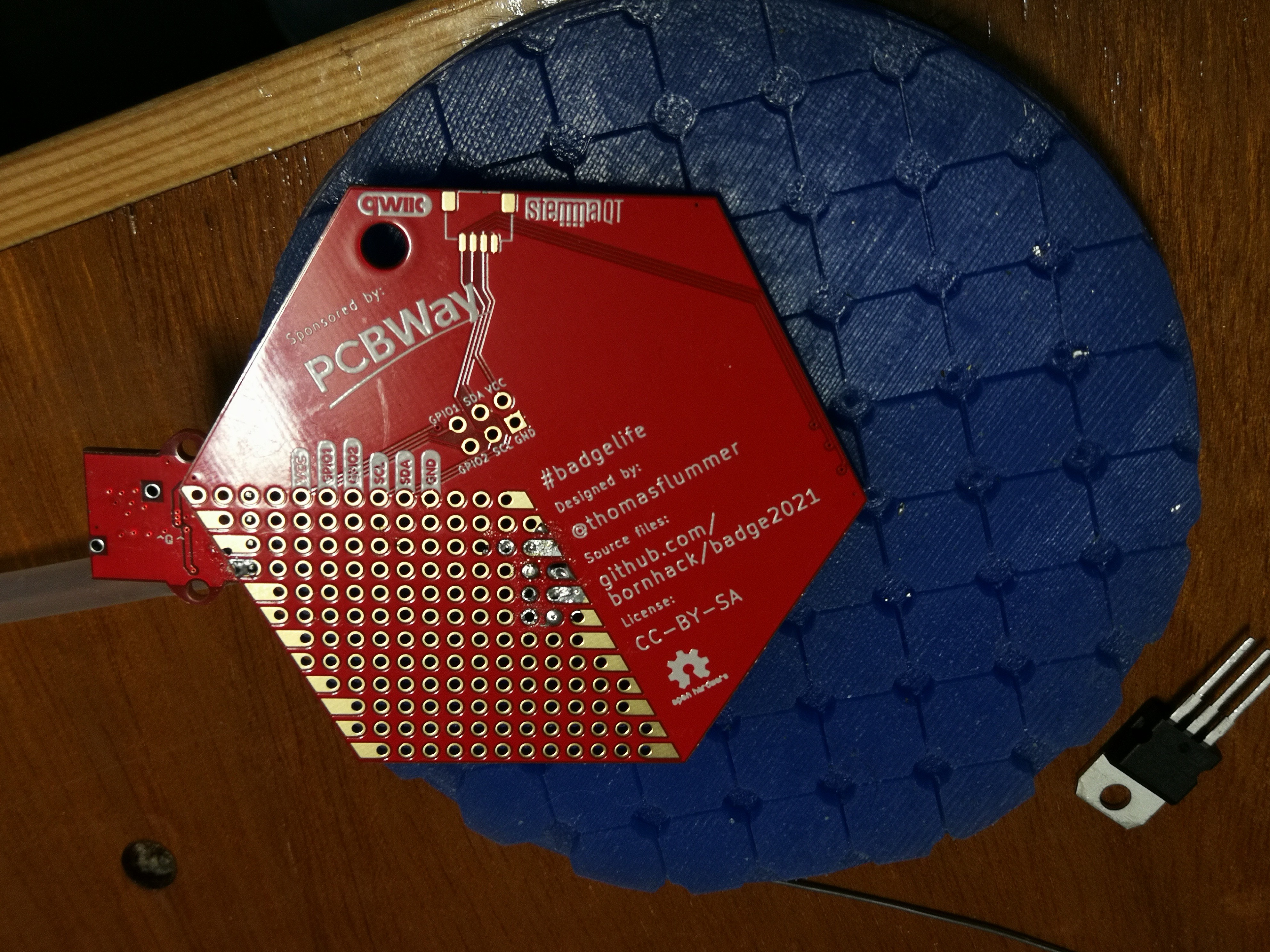
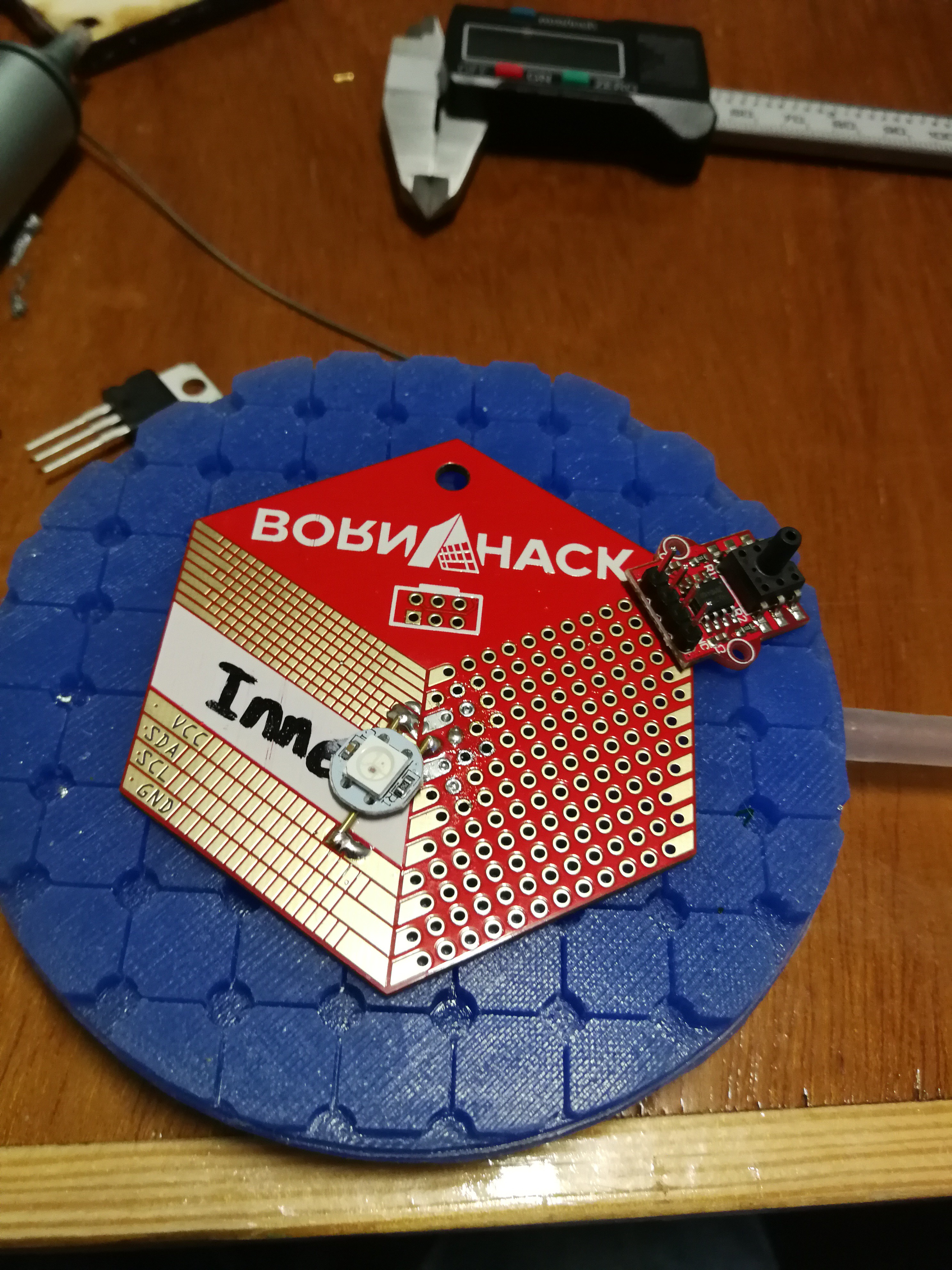
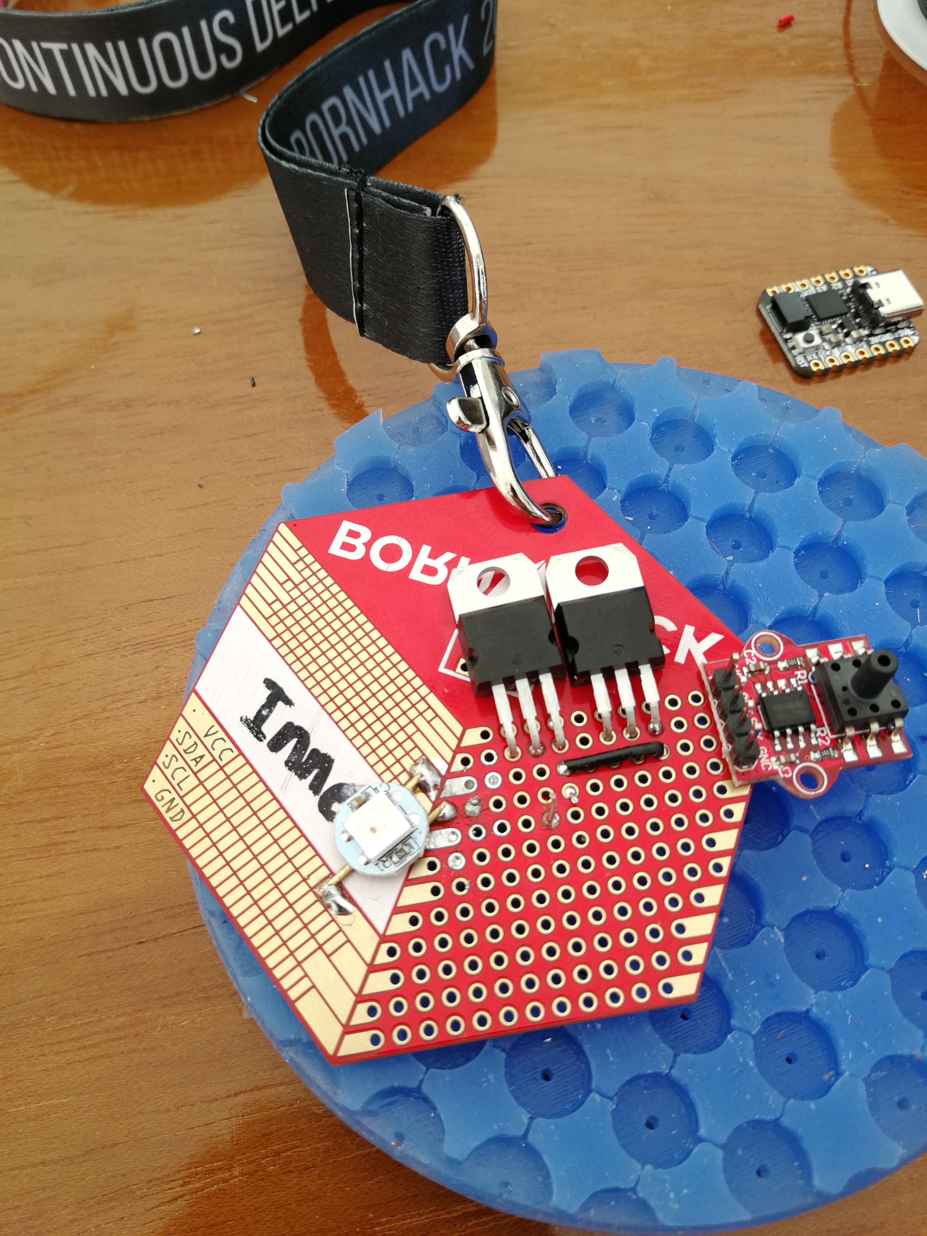
• 1
    Solder NeoPixel

    These pcb NeoPixels have pads on their underside, therefore making it impossible to solder them to the flat service of the badge. To circumvent this solder some metal rods to the pads. Make wires a little longer to cut to size later for easier placement.

    Place the NeoPixel on the SMD part of the badge so it is as much center as possible. Though this also doesn't need to be perfect since the bubble goes on top and will diffuse the light anyway.

  • 2
    Add presure sensor module

    Add the pressure sensor. Take the following into account, we need as much space as possible for both the other components as well as the bubble. Therefore we solder it portruding out of the badge. The connector for the tube needs to face the front otherwise the tube might cause the badge to tilt/spin. The headers on the module will point quite far in the direction your chest will be on the finished badge. Desolder them and flip them around so the short end faces down.

    Place them in the holes of the badge, the header pins will be just short of flush with the underside of the badge. Solder them on underside of the badge.

    The regidity of this construction will be from the small overlaps of the module and the badge combined with the fact that the module lays very flat on the badge. There is no planned mechanical strain on the module. Though it still might be a weak point to be carefull about.

  • 3
    Place Transistors

    Place the 2 TIP120's in the second row of the prototype board (first row has qwic and SAO breakouts). Bend the leads in such a way that the transistor can lay flat on the badge, don't push the leads too far in so bending is easier. Solder the them in place.


    On the back add the resistors and diodes between the pins of the transistor based on the schematic below. (The resistors are different values and we don't use the ceramic cap, diagram is more as illustration).


    Connect the middle and right pin with a SMD schottky diode. and add a resistor on the left pin of both transistors, these will later be connected to the pins on the micro controller handeling the motors and valves. Connect one off the Emitter pins to the GND on the top row of the trough hole PCB and also coneect bot emitters to eachother via a wire (shown as black wire in first picture).

    The GND will be connected to the microcontroller in a later step.