 Inne
Inne-
1Solder NeoPixel
![]()
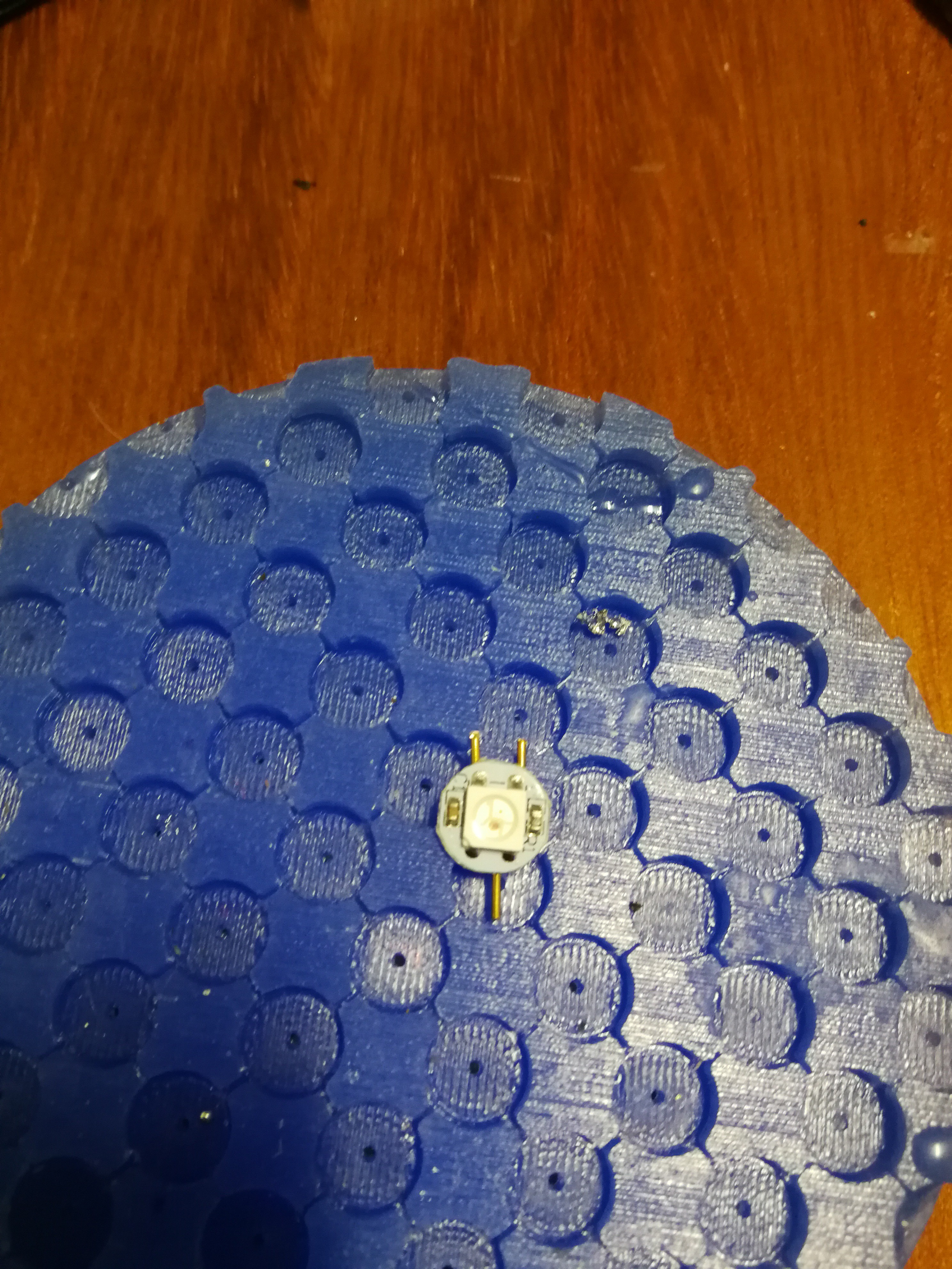
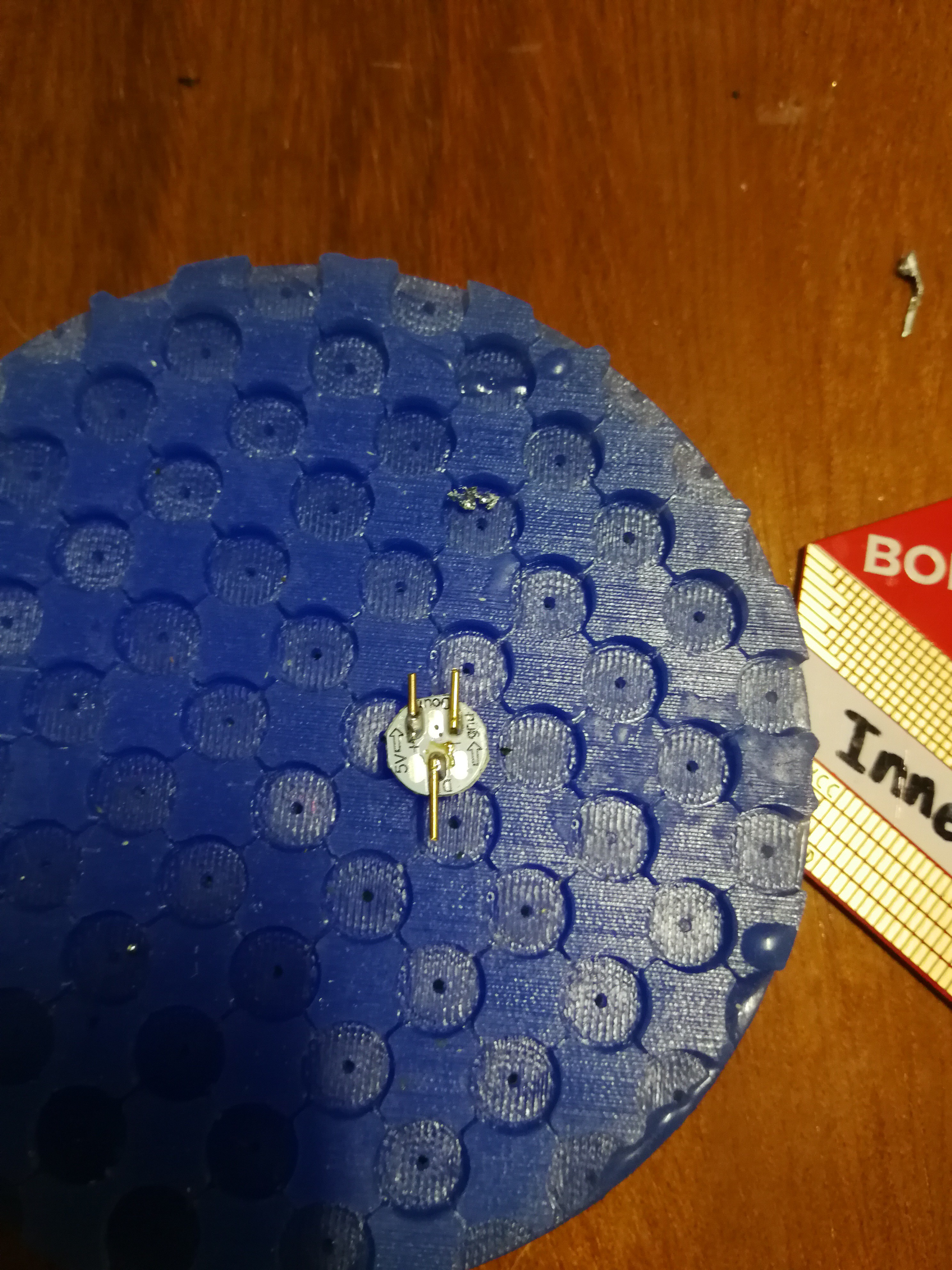
These pcb NeoPixels have pads on their underside, therefore making it impossible to solder them to the flat service of the badge. To circumvent this solder some metal rods to the pads. Make wires a little longer to cut to size later for easier placement.
![]()
![]()
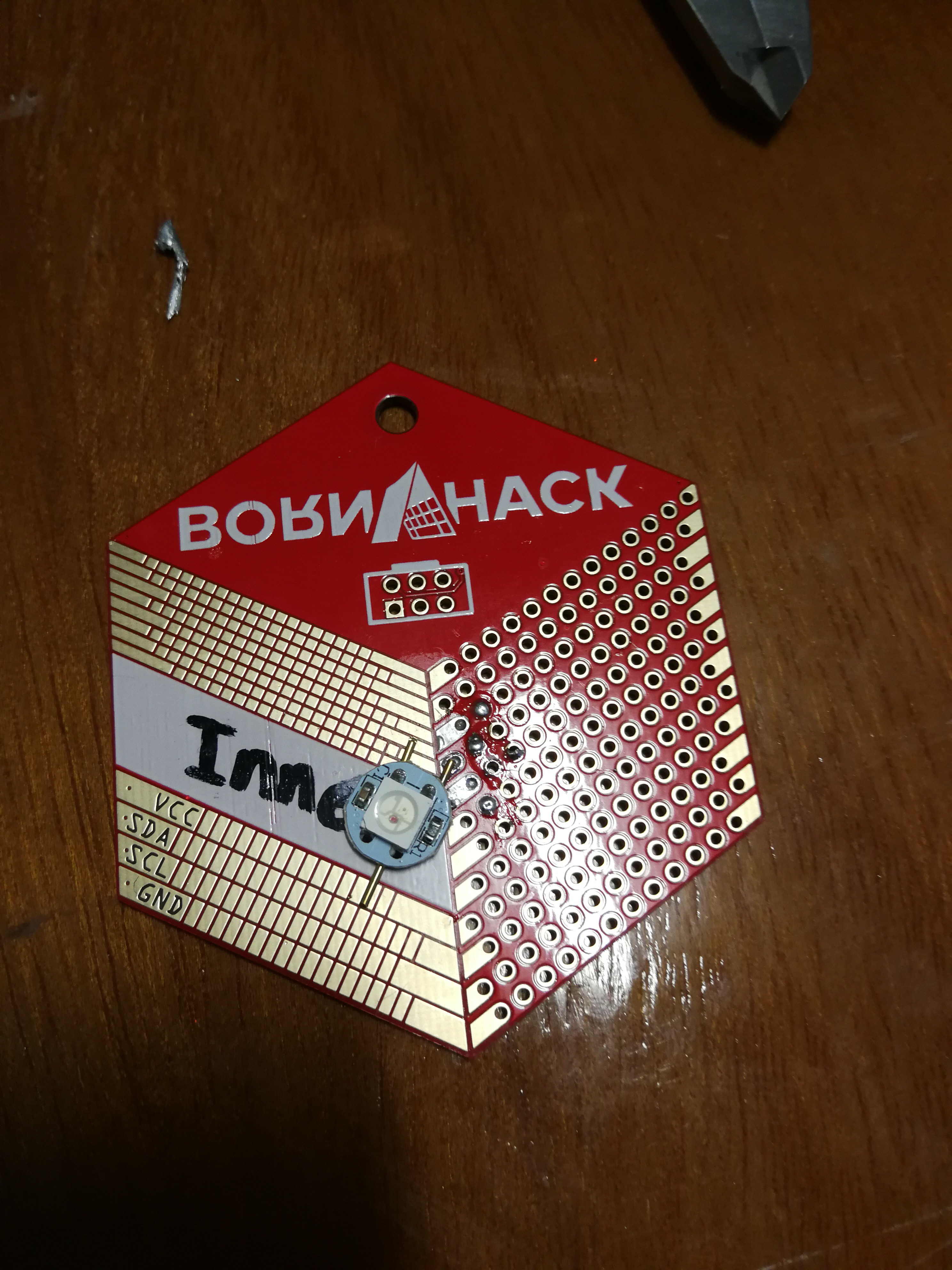
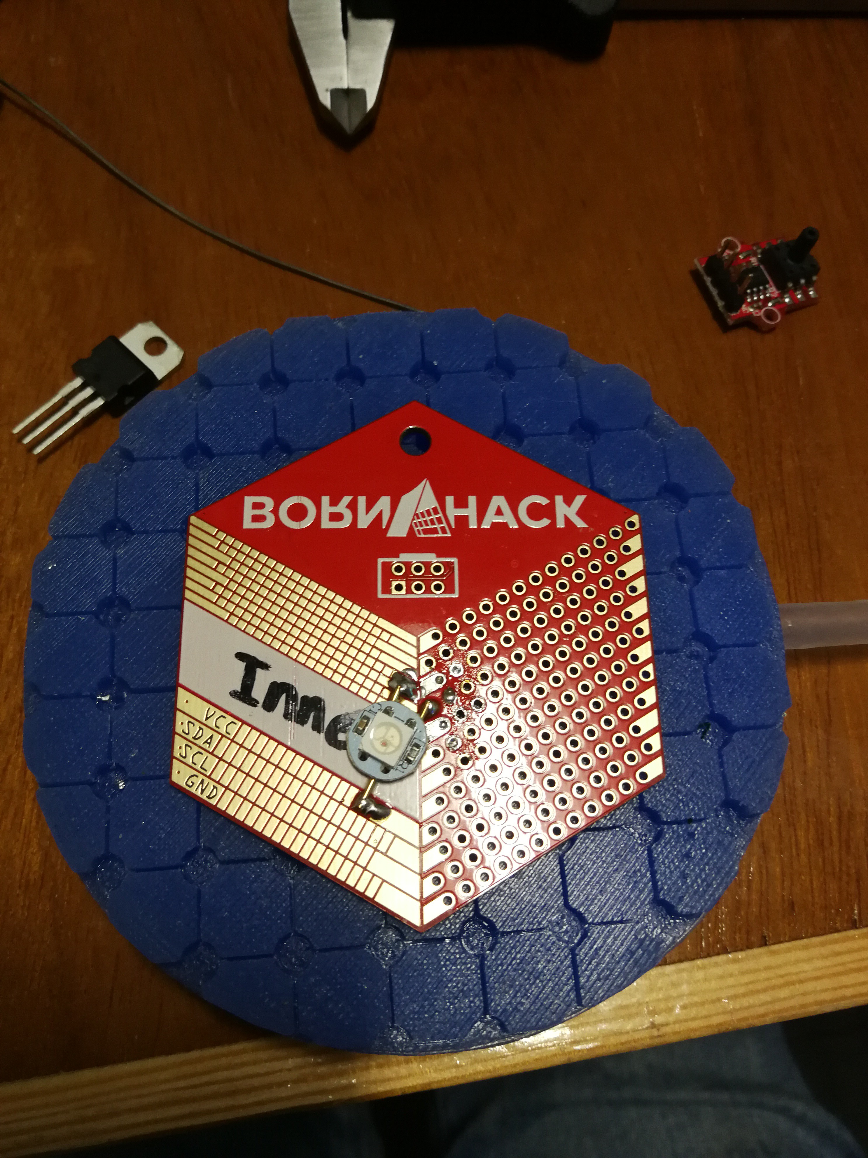
Place the NeoPixel on the SMD part of the badge so it is as much center as possible. Though this also doesn't need to be perfect since the bubble goes on top and will diffuse the light anyway.
![]()
![]()
-
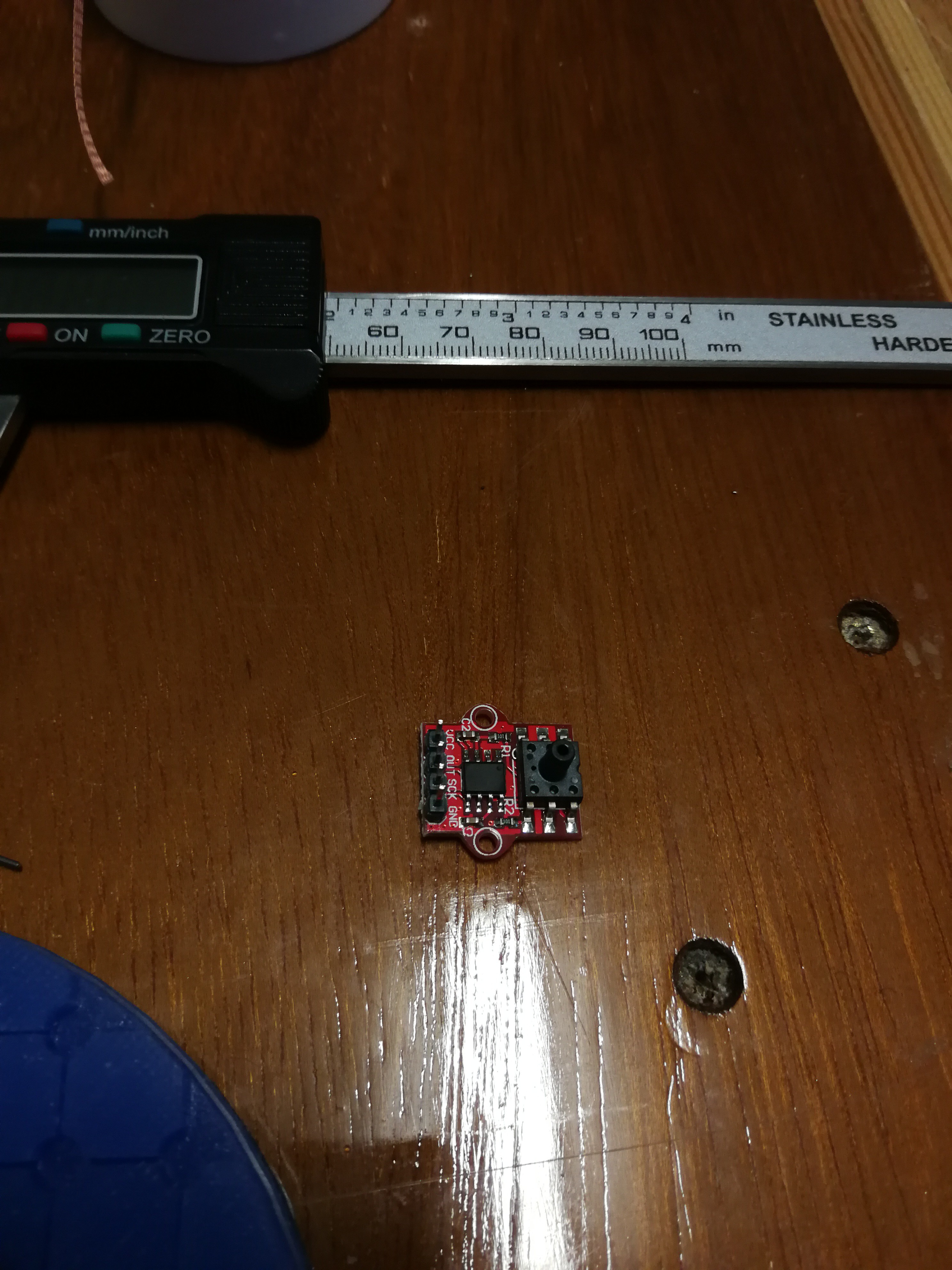
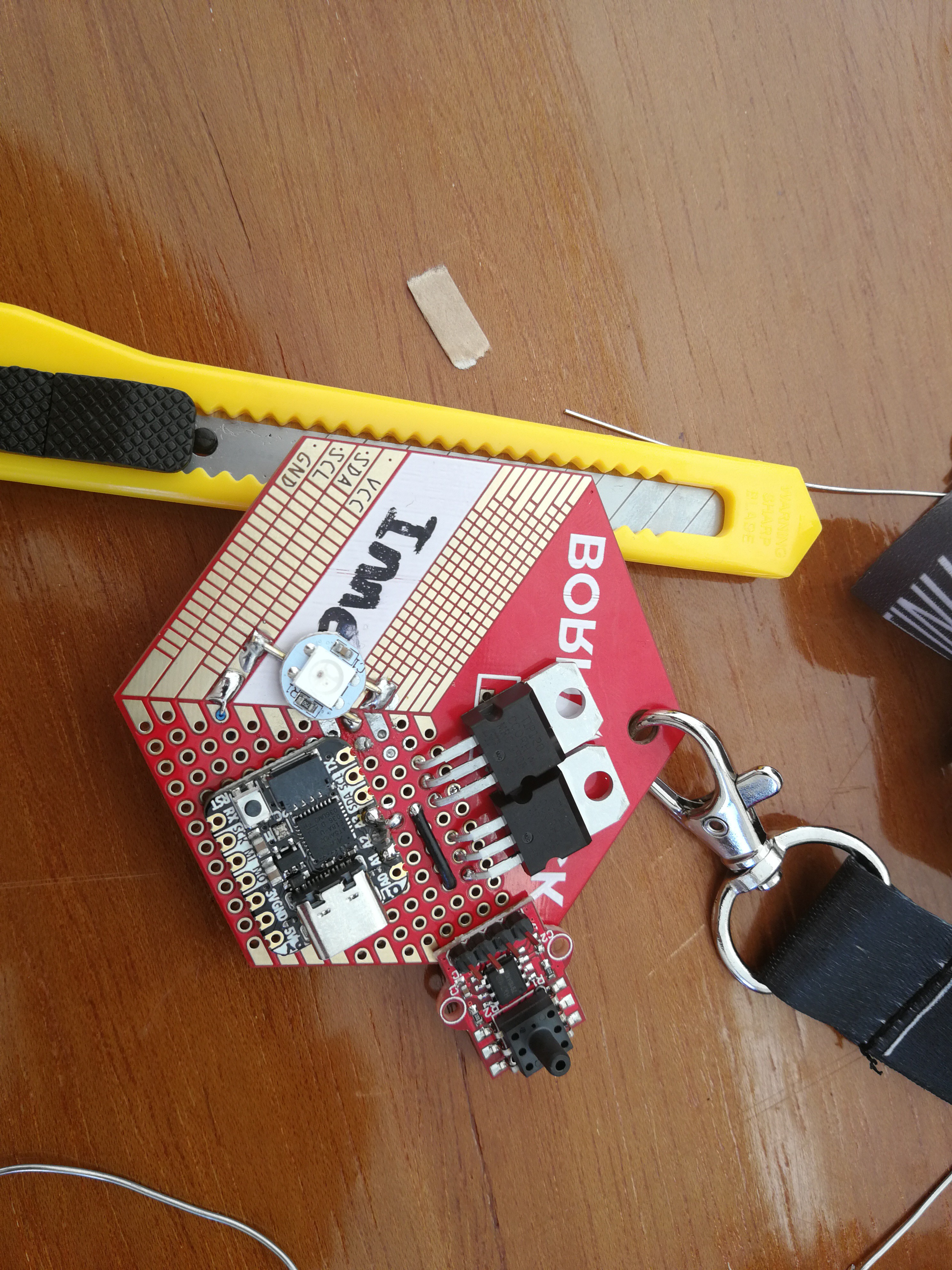
2Add presure sensor module
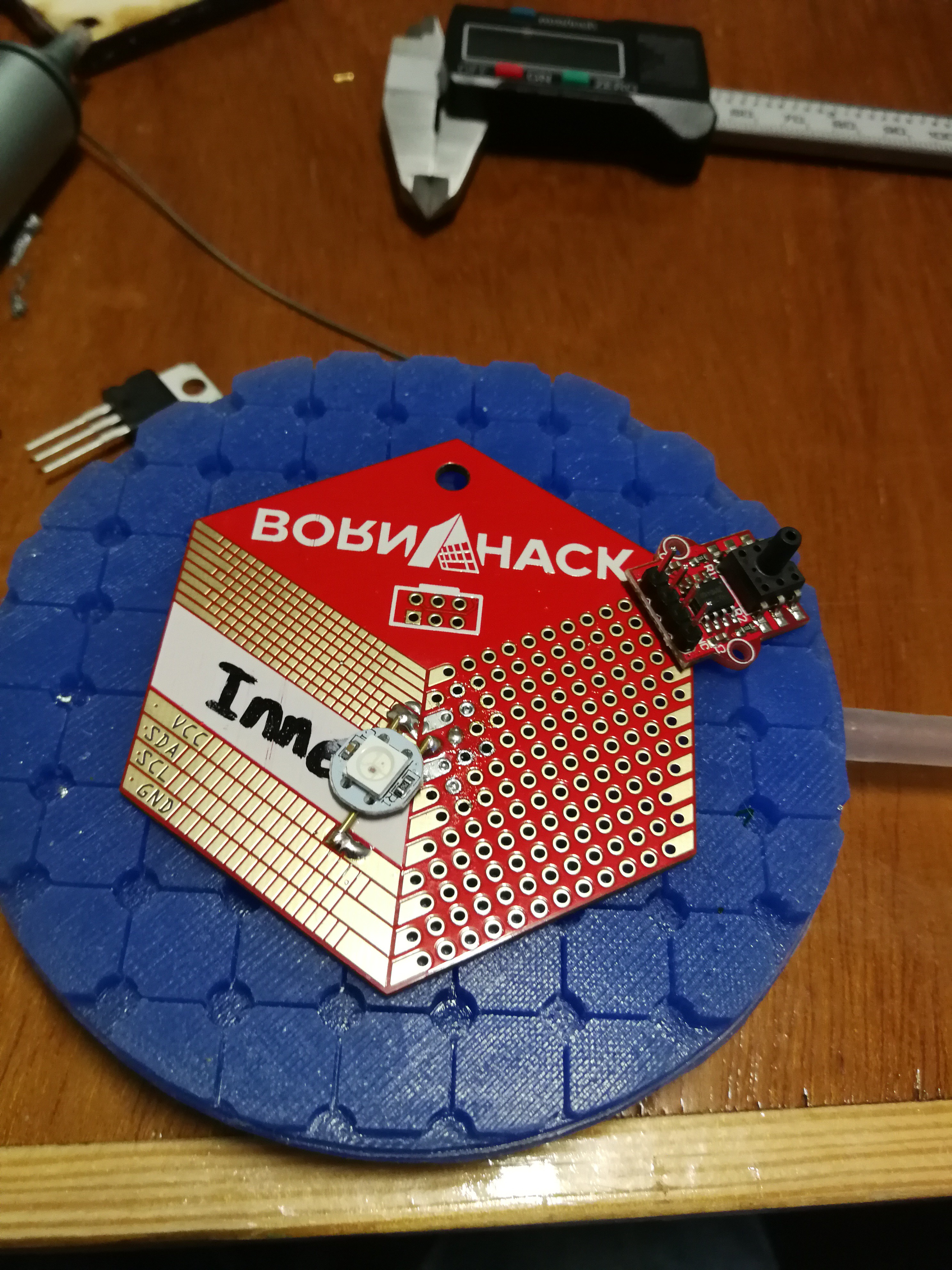
Add the pressure sensor. Take the following into account, we need as much space as possible for both the other components as well as the bubble. Therefore we solder it portruding out of the badge. The connector for the tube needs to face the front otherwise the tube might cause the badge to tilt/spin. The headers on the module will point quite far in the direction your chest will be on the finished badge. Desolder them and flip them around so the short end faces down.
![]()
Place them in the holes of the badge, the header pins will be just short of flush with the underside of the badge. Solder them on underside of the badge.
![]()
The regidity of this construction will be from the small overlaps of the module and the badge combined with the fact that the module lays very flat on the badge. There is no planned mechanical strain on the module. Though it still might be a weak point to be carefull about.
![]()
-
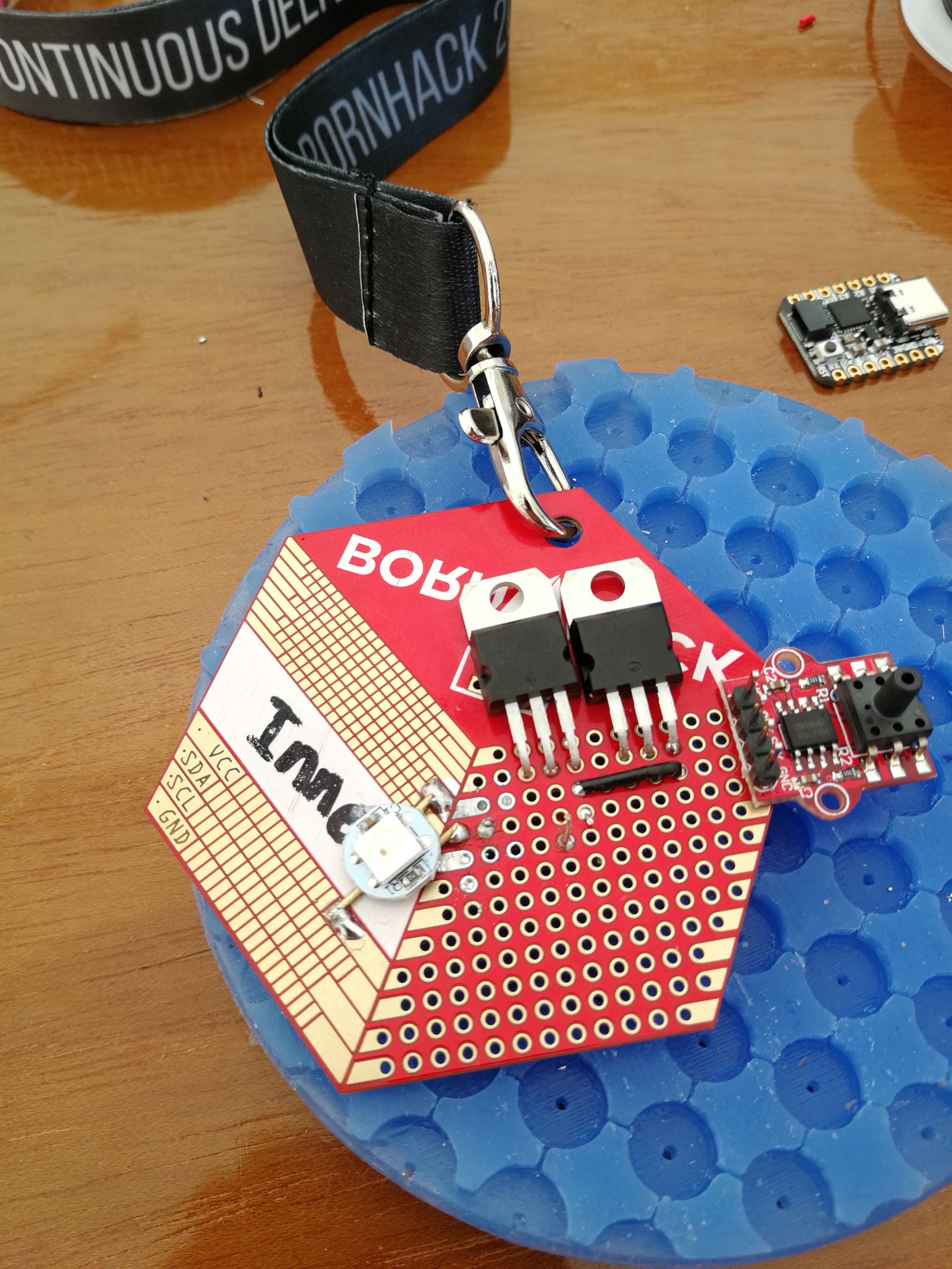
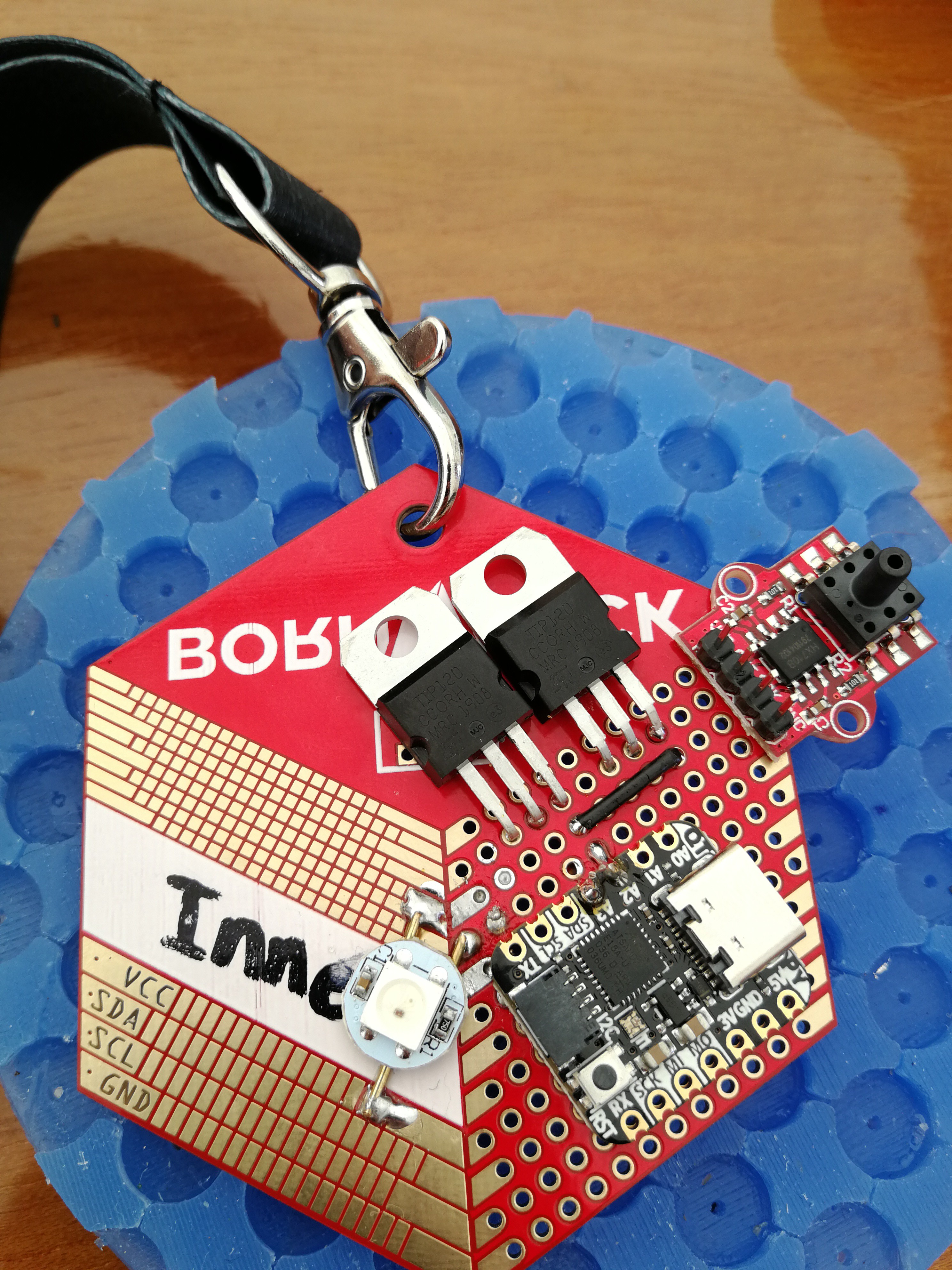
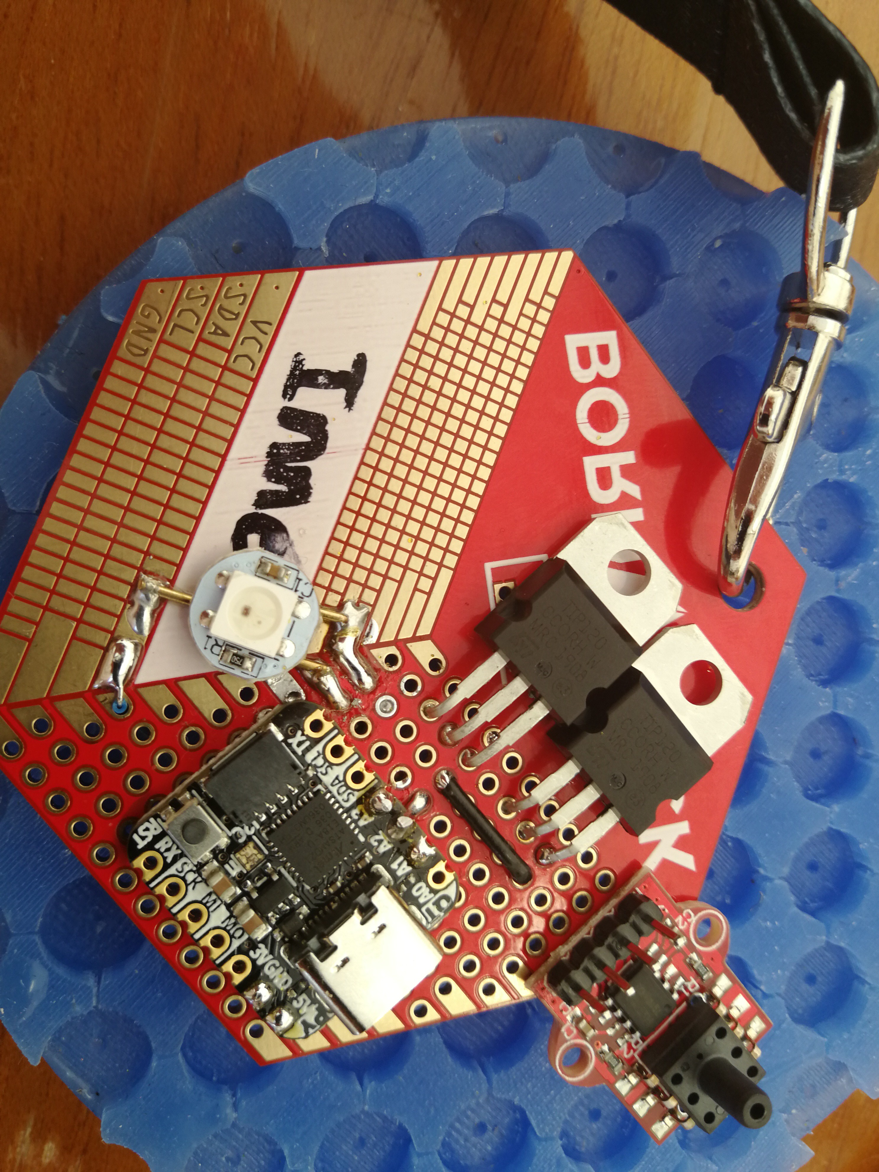
3Place Transistors
Place the 2 TIP120's in the second row of the prototype board (first row has qwic and SAO breakouts). Bend the leads in such a way that the transistor can lay flat on the badge, don't push the leads too far in so bending is easier. Solder the them in place.
![]()
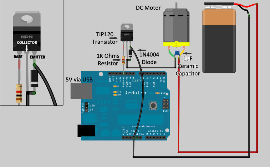
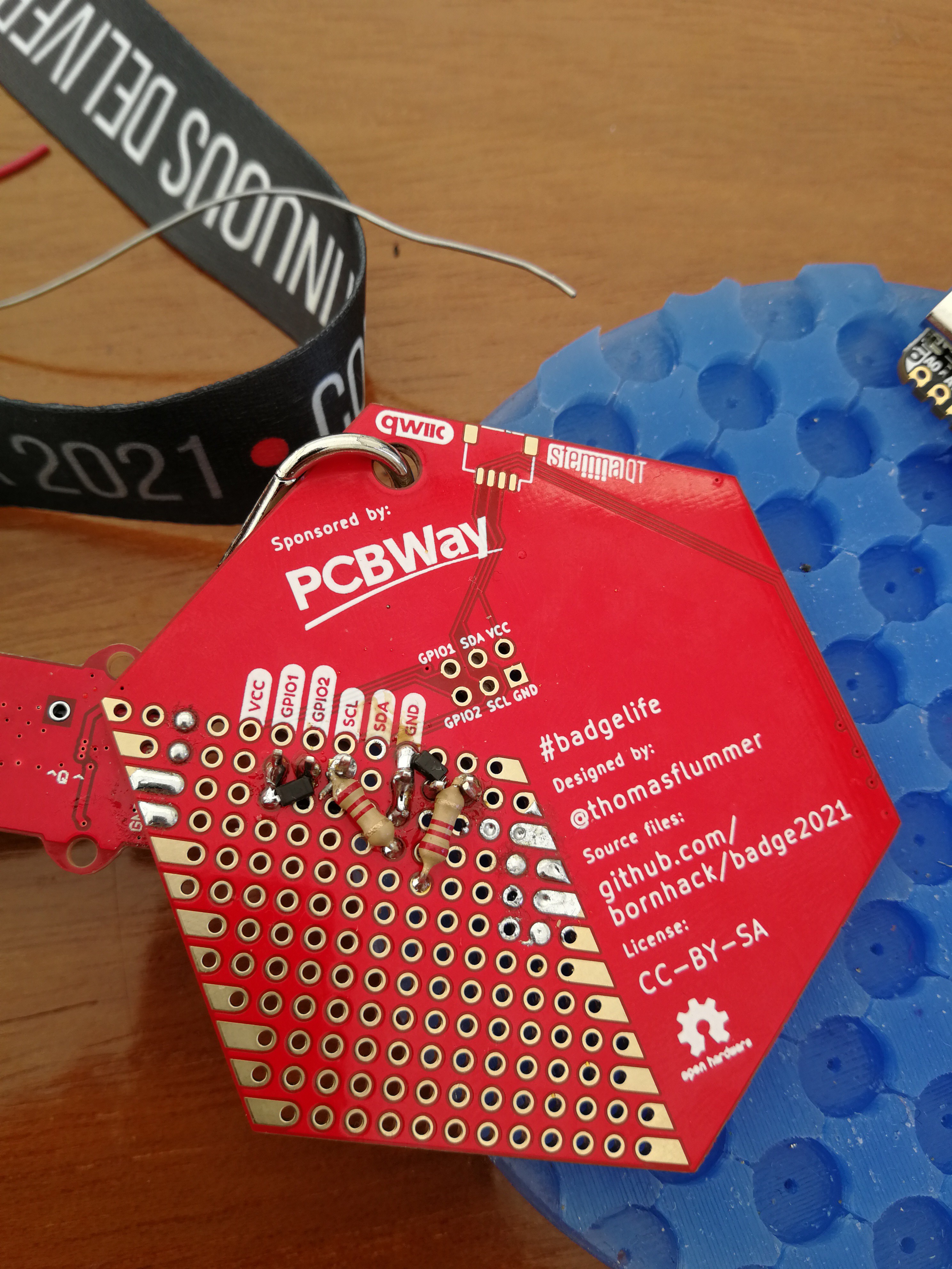
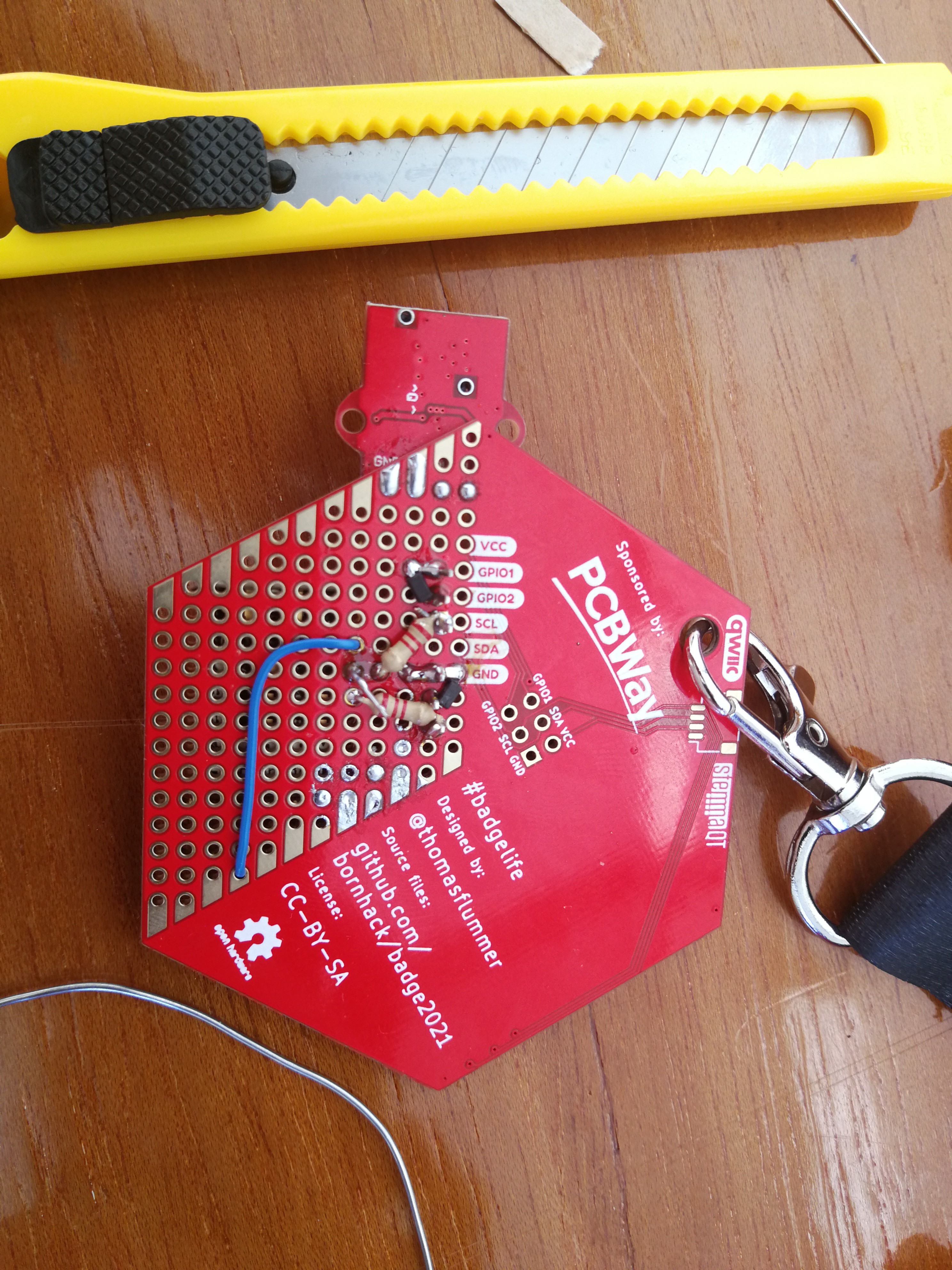
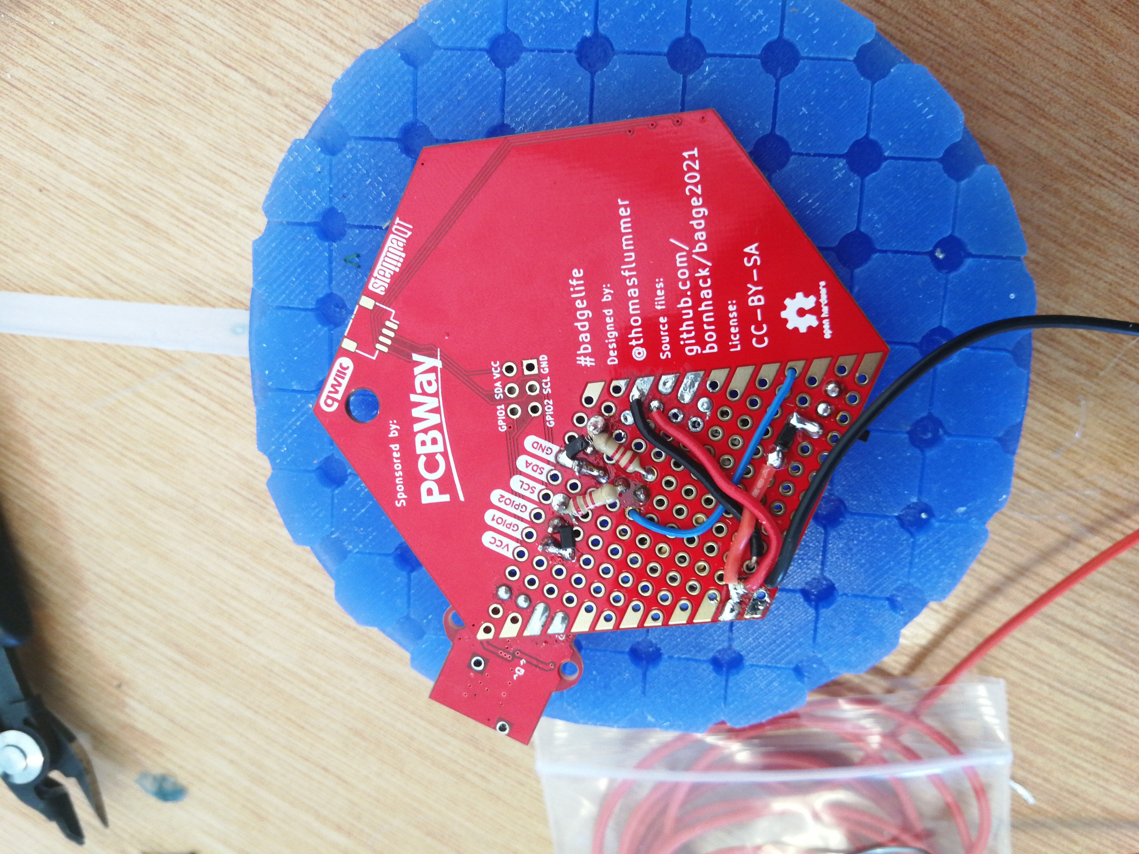
On the back add the resistors and diodes between the pins of the transistor based on the schematic below. (The resistors are different values and we don't use the ceramic cap, diagram is more as illustration).![]()
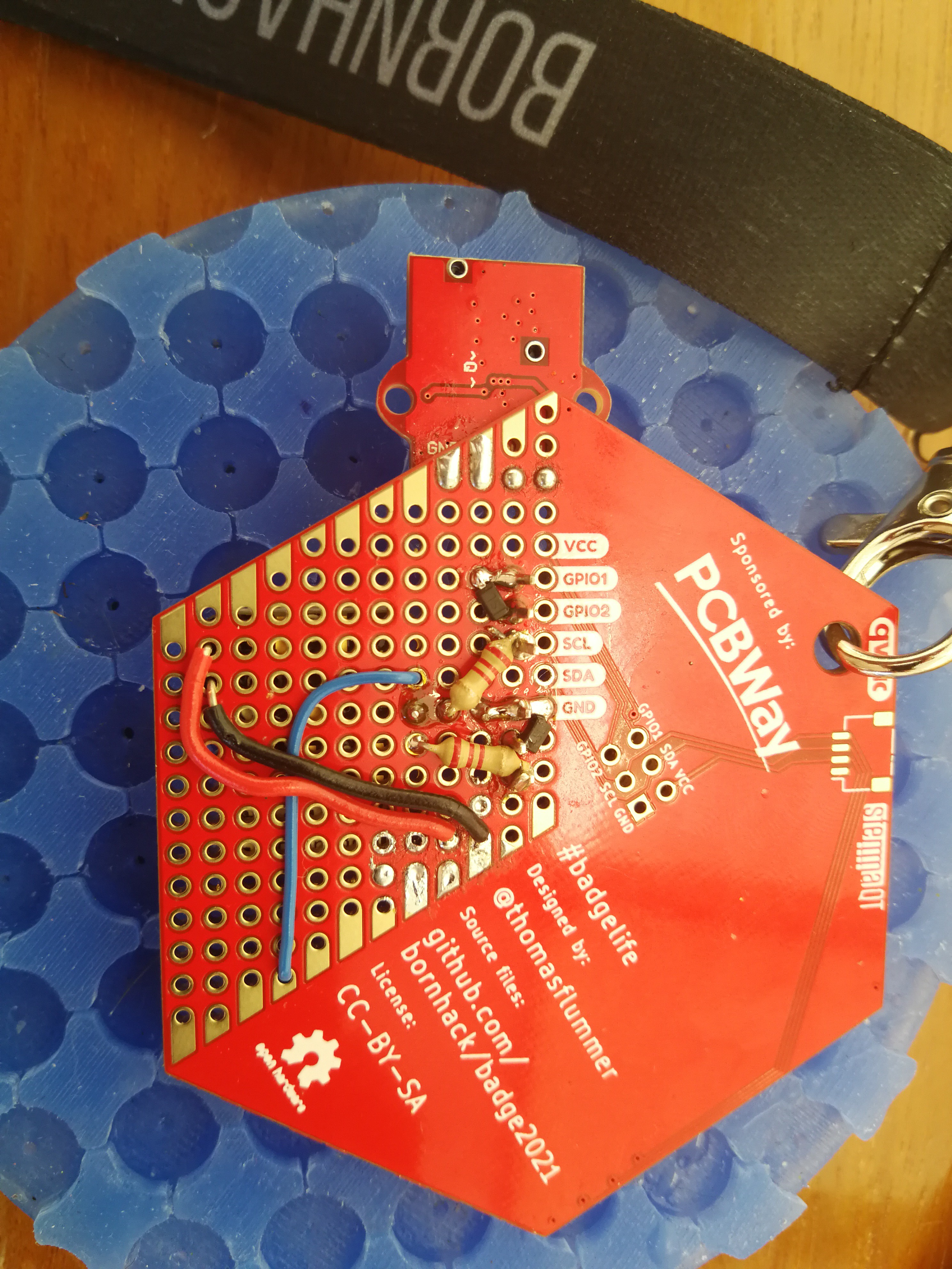
Connect the middle and right pin with a SMD schottky diode. and add a resistor on the left pin of both transistors, these will later be connected to the pins on the micro controller handeling the motors and valves. Connect one off the Emitter pins to the GND on the top row of the trough hole PCB and also coneect bot emitters to eachother via a wire (shown as black wire in first picture).![]()
The GND will be connected to the microcontroller in a later step.
-
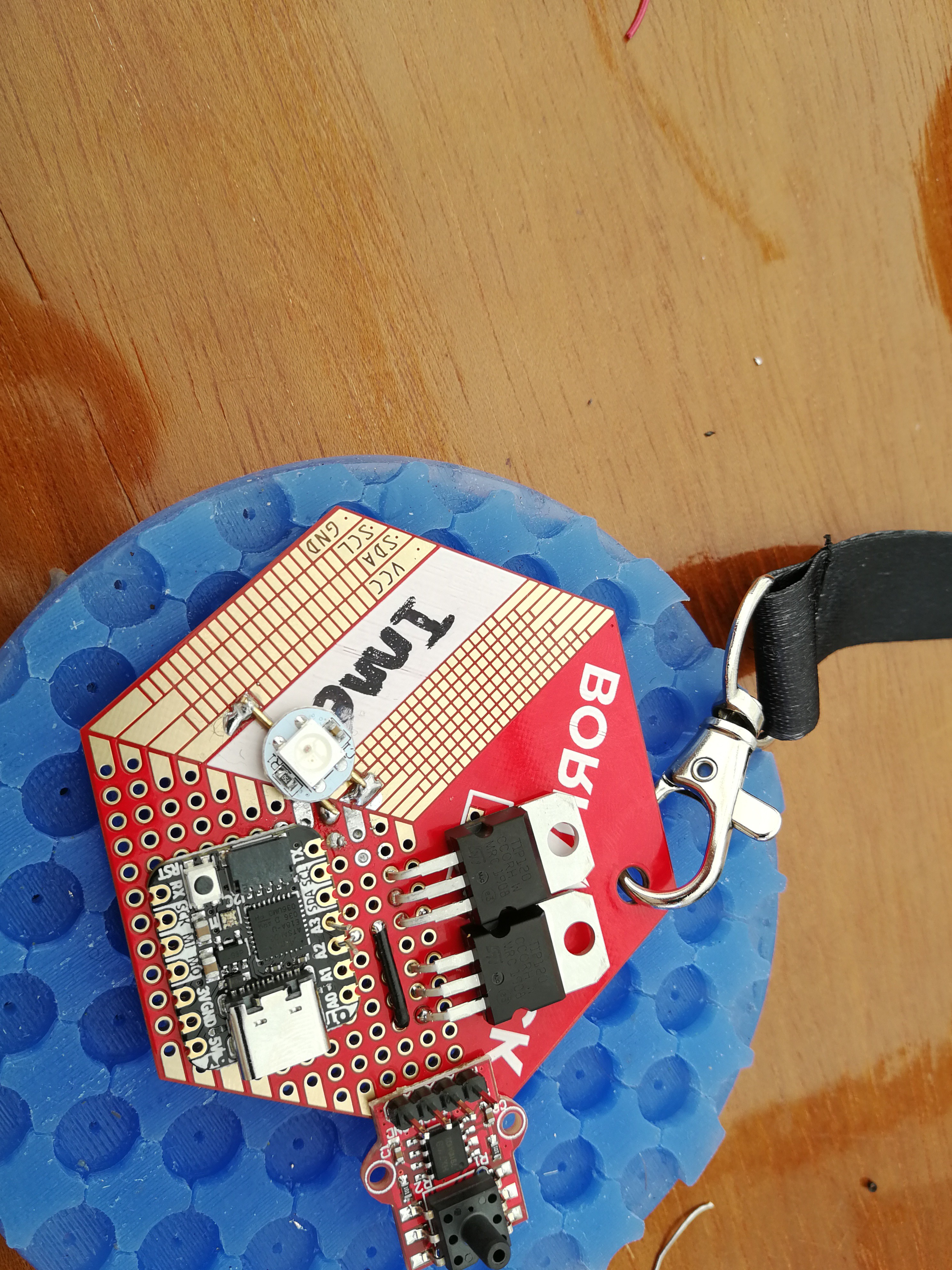
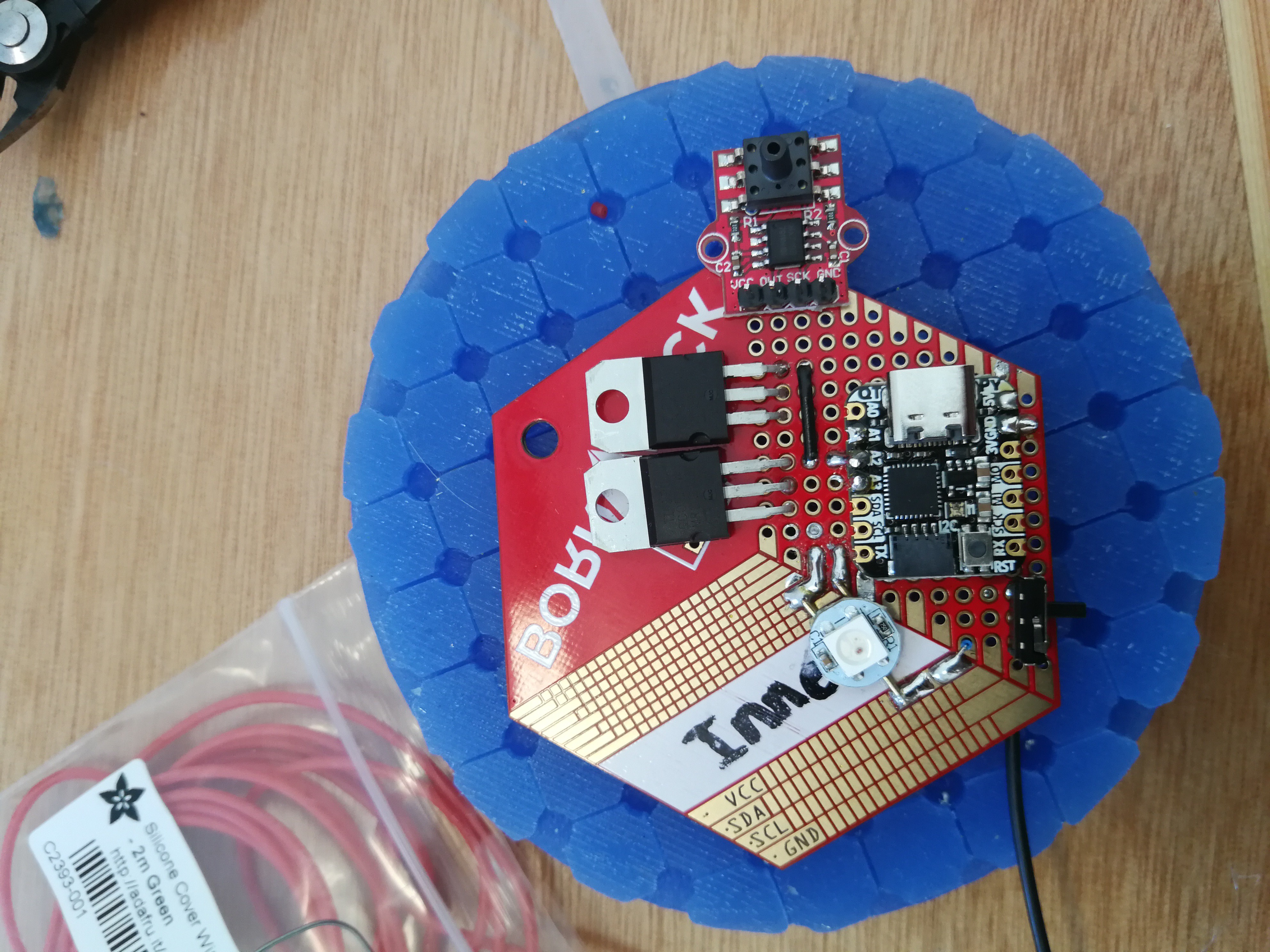
4Place the microcontroller
Place the microcontroller in a way that it is easy to connect the resistors attached to the transistors from the previous step. Leave the bottom row empty to make it easier to expand functionality in the future.
![]()
Solder the microcontroller in place by either placing the resistor leads trough its holes or solder bridging to the coresonping pins (A2 and A3) .
![]()
-
5Connect NeoPixel
Connect the A1 pin of the microcontroller with the data pin of the NeoPixel (Middel downward facing) by running a wire (blue) to the pad adjacend to the SMD section.
![]()
![]()
Connect the ground and vcc of the upper parts with to the corresponding parts of the microcontroller.
![]()
Bridge the troughhole pads and the SMD pads where necessary.![]()
-
6Place on/off switch
Since our badge is battery operated, it is nice to add a switch. It allows for easy shutdown instead of having to pry the batteries out everytime it is not used. Place it near the bottom center wiring the middle pin to the wire leading to the positve lead of the battery and the left pin to vcc of the microcontroller. This way pushing the switch towards the controller turn it on, which is easier to remember.
![]()
Because we are powering the QTPy via the 5V pin Adafruit recommends putting a diode (any diode) between the battery and 5V. Place another SMD schottky diode after the switch pin and connect a wire from its other end to 5V.
![]() In this picture the ground wire is already connected to GND and leads down to the battery connector. 5V will ve wired up in the next step.
In this picture the ground wire is already connected to GND and leads down to the battery connector. 5V will ve wired up in the next step. -
7Wire transistors
Connect the middle (collector) pins of the transitor with (green) wires. They will eventually connect to the airpump and solenoid. There iin't a lot of room left to place the wires, especially for the right transistor. A trick for that is to strip the wire a bit longer and pass it trough a further away hole and solderit to the pin directly. Make sure to use (a small) tube of heat shrink to prevent shorts.
![]() The wires should be connected with direct path to the emitter pin, so don't place them after the diode.
The wires should be connected with direct path to the emitter pin, so don't place them after the diode.![]() Also connect the middle pin of the switch with a wire that will go to the positive lead of the battery.
Also connect the middle pin of the switch with a wire that will go to the positive lead of the battery.![]()
Connect the top row marked GND to the nearest ground (the Gnd of the NeoPixel).
-
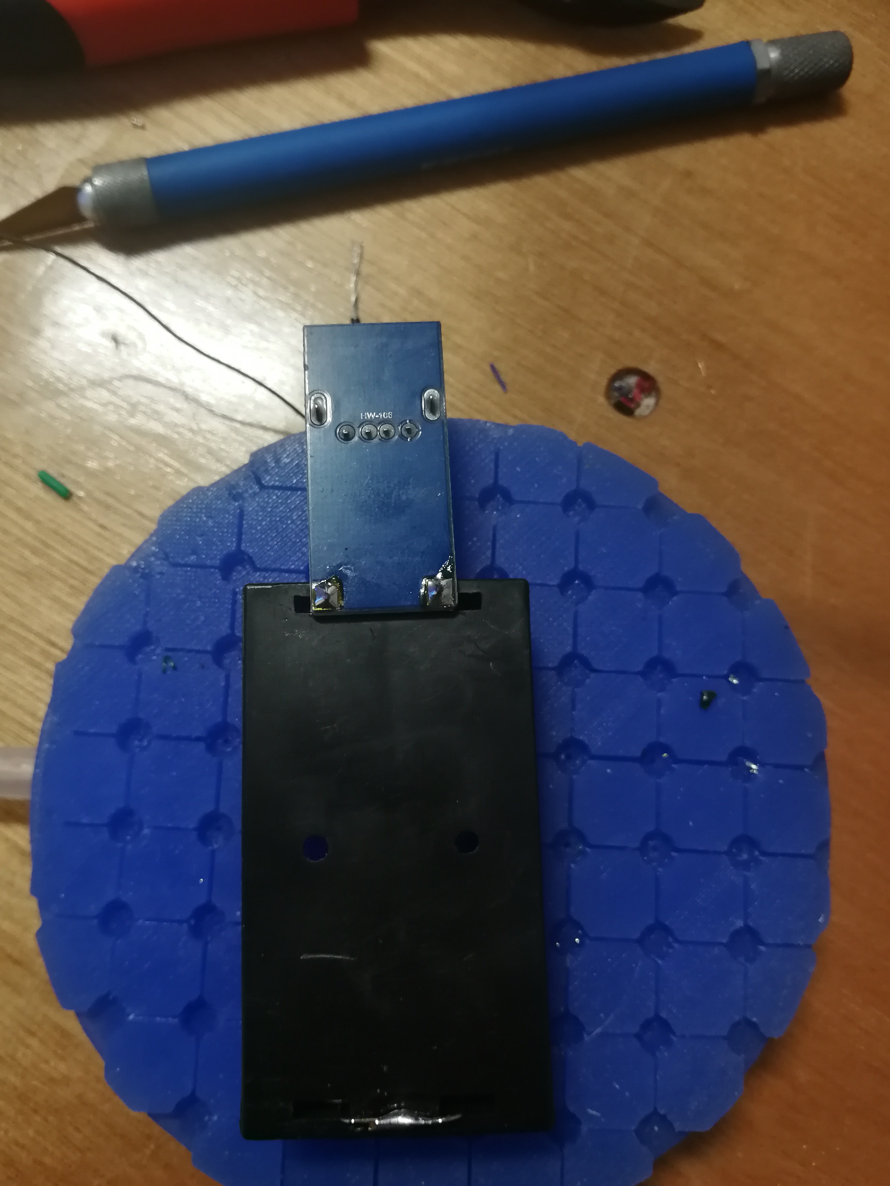
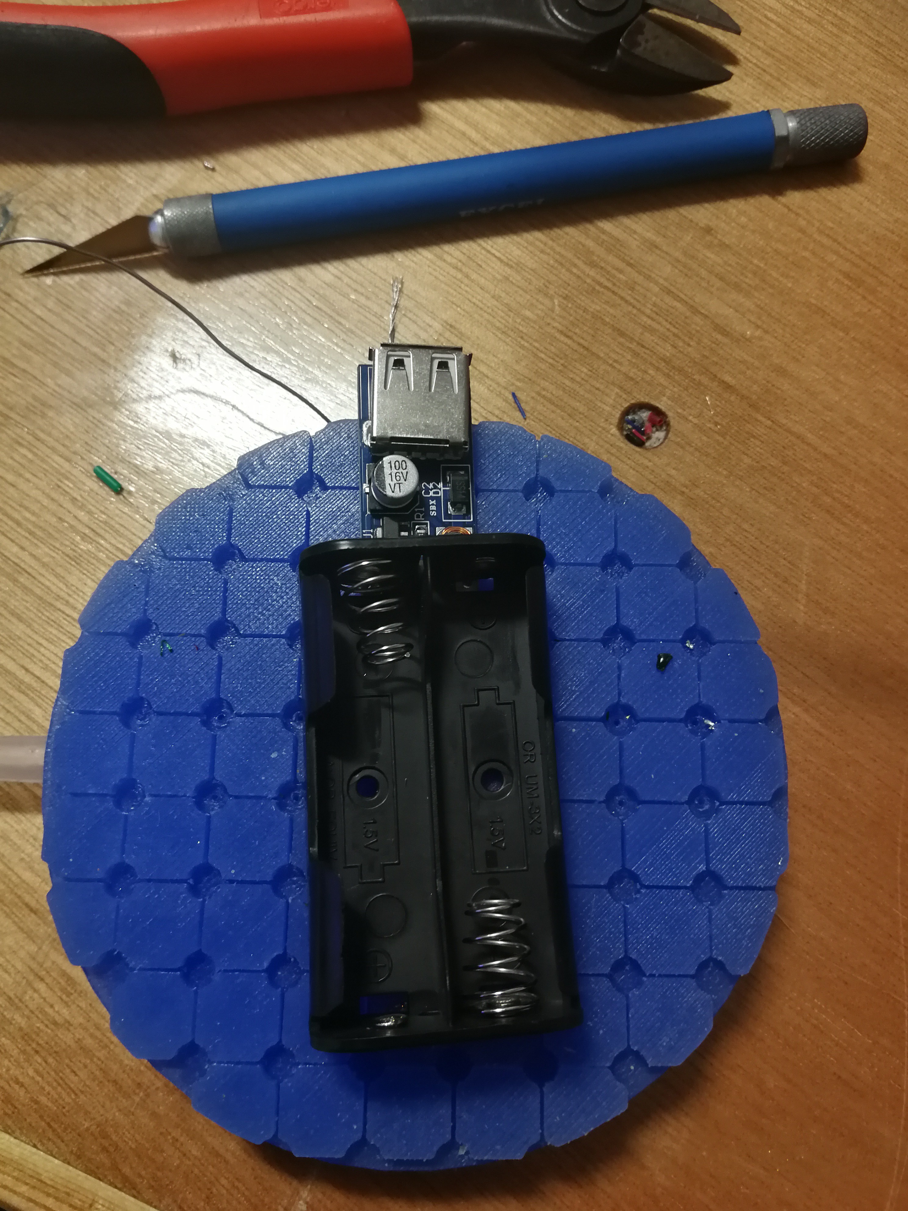
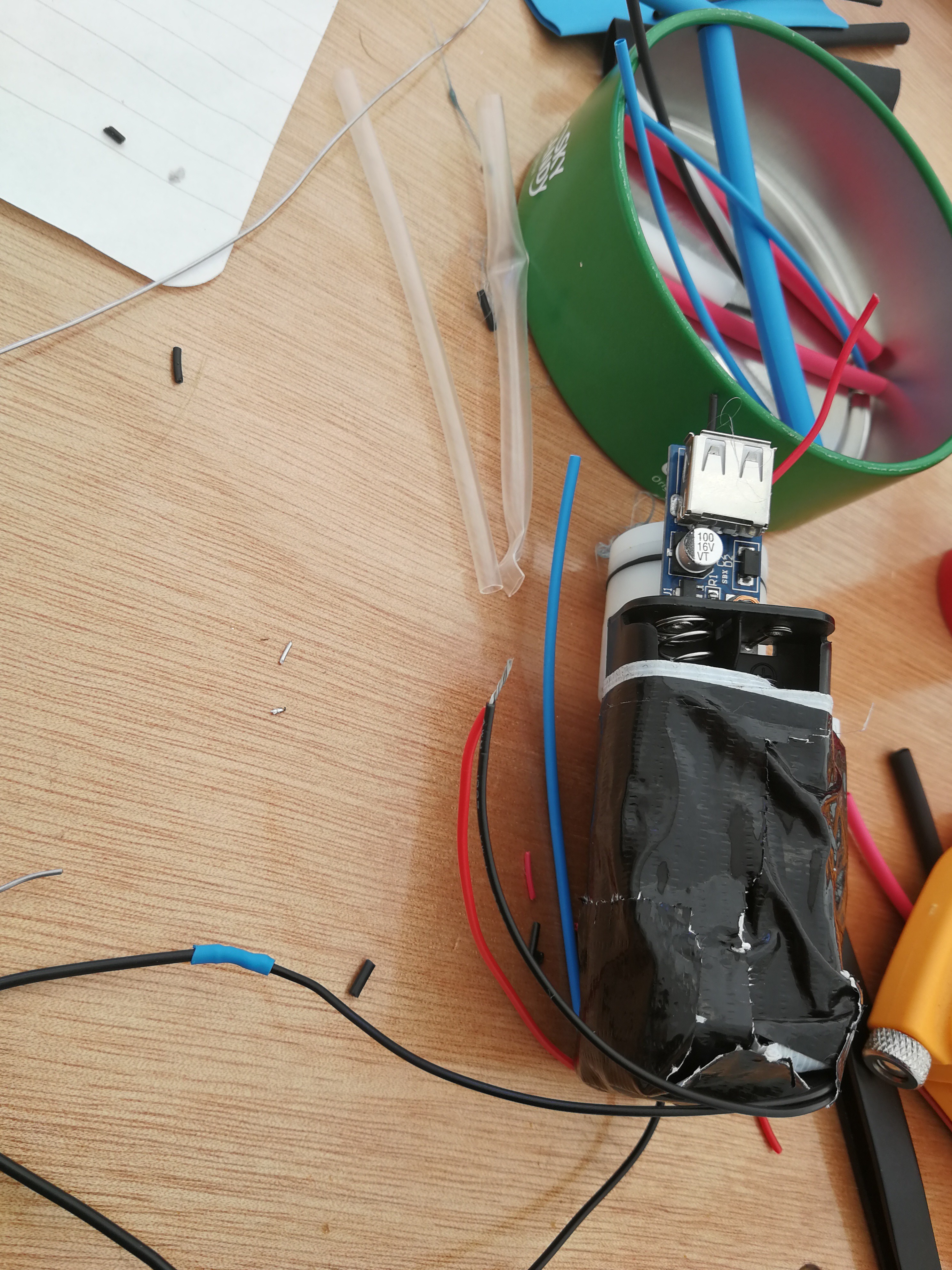
8Make battery, pump and solenoid
Since we use 2AA batteries the current output would be 3V but the airpump runs on 6V (ish). Connect the battery holder to a lipo discharge protection circuit which will boost the output to 5V. This is sufficient to power the airpump.
![]()
![]()
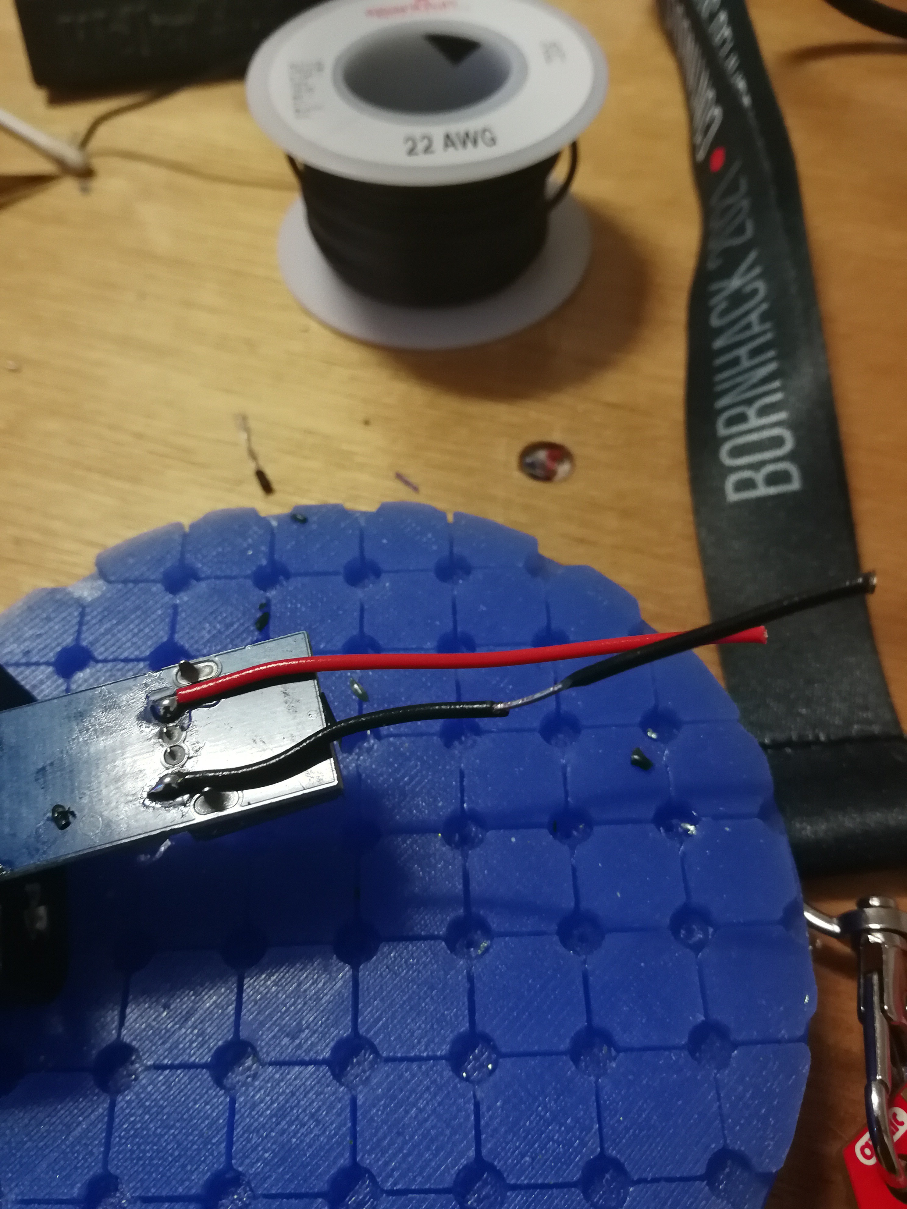
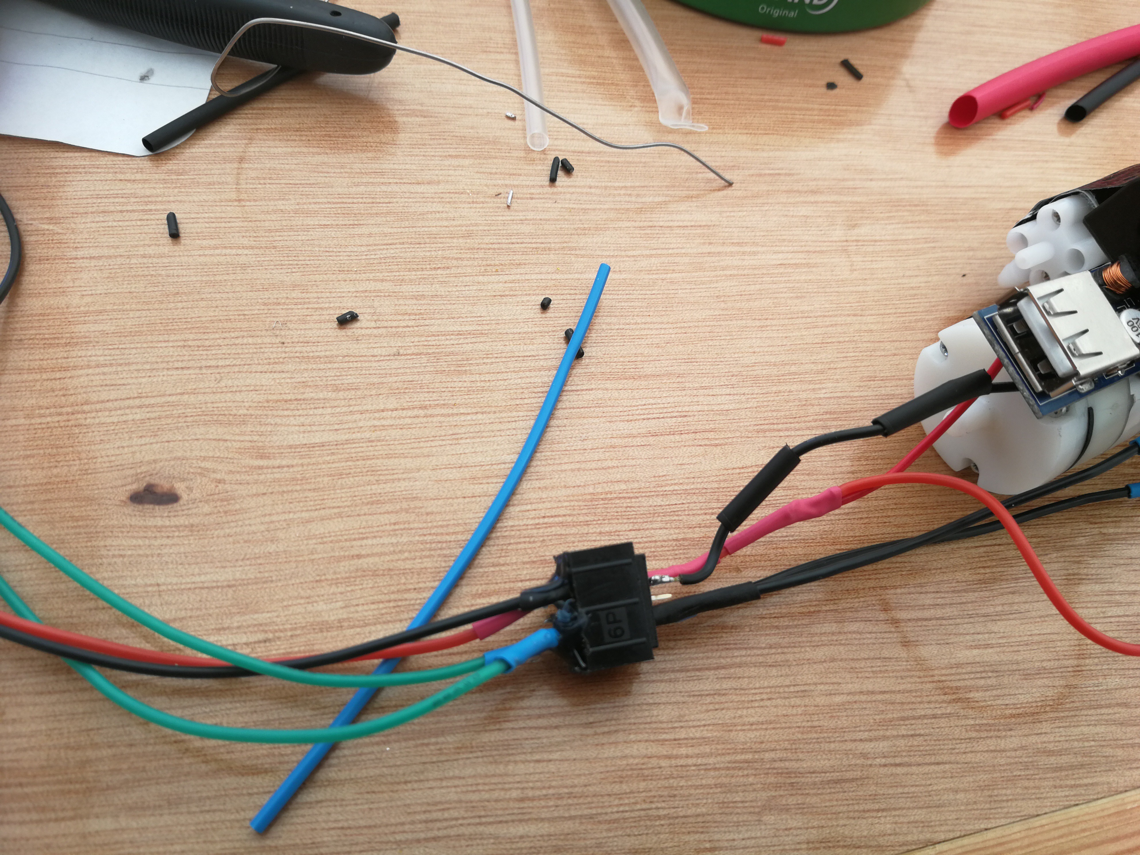
Connect wires to the outher most pins of the usb connection (the + and -).
![]()
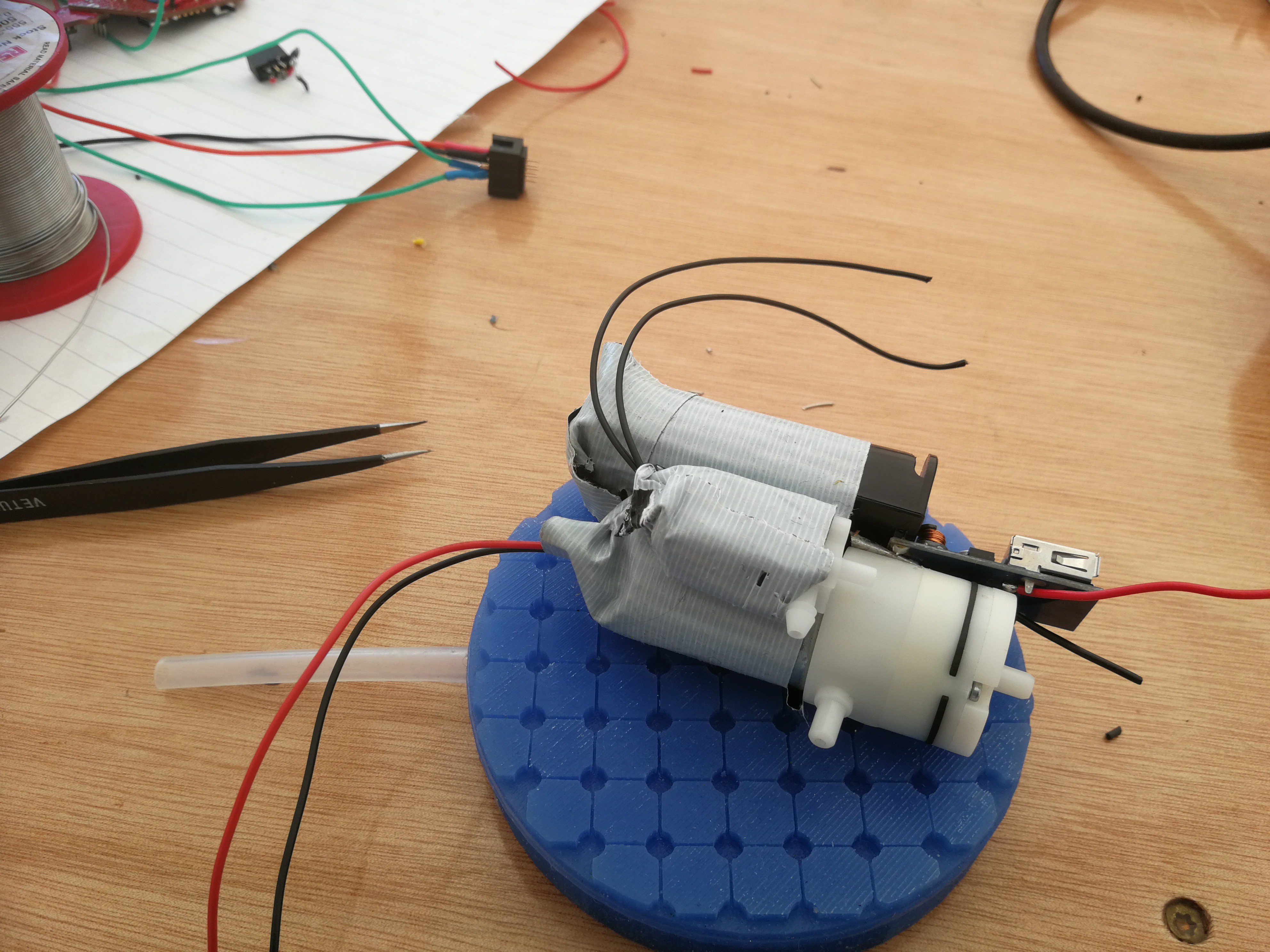
Solder one lead of the airpump and one lead of the solenoid to the positive (red) wire from the protection circuit. Also make an case for it using ducttape to keep everything together.
![]()
![]()
![]()
-
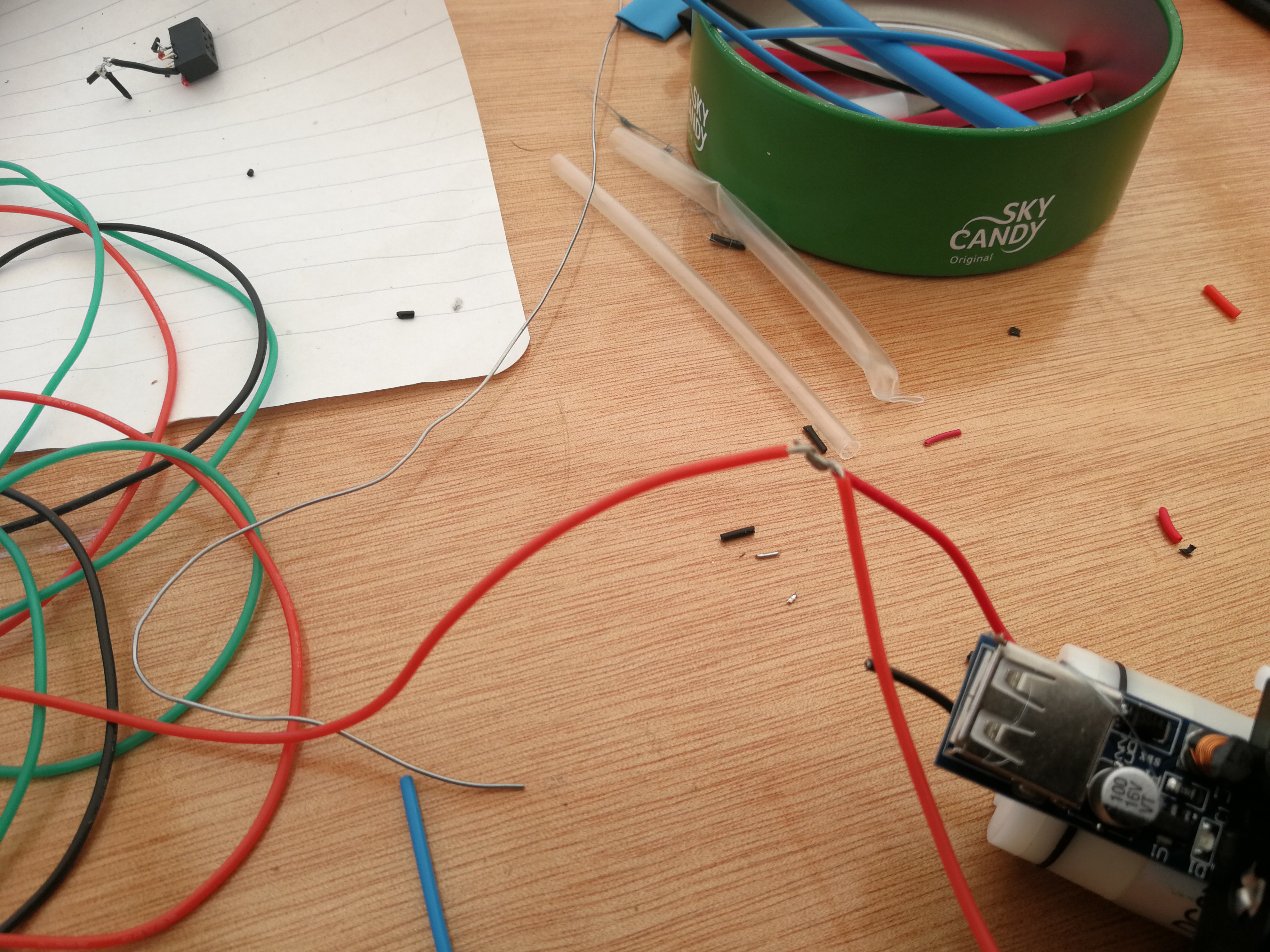
9Wire connector
Too keep the badge and the battery/pump seperate we connect them via a SAO connector. Technically we don't need to adhere to the SAO standard but it is little to do it anyway.
![]()
From the badge side connect the green transistor wires to GPIO 1 and 2. Connect the red and black wire to Vcc and Gnd respetively. Do this on the male connector, in hindsight I choose the wrong genders for the badge and the battery.
![]()
On the battery side connect the other leads of the motor to one of the GPIO pins of the SAO connector and the other lead of the solenoid to the remaining GPIO of the SAO connector. Connect positve and negative from the protection service to respectivly 3v3 (even tough its actually 5V) and Gnd.
-
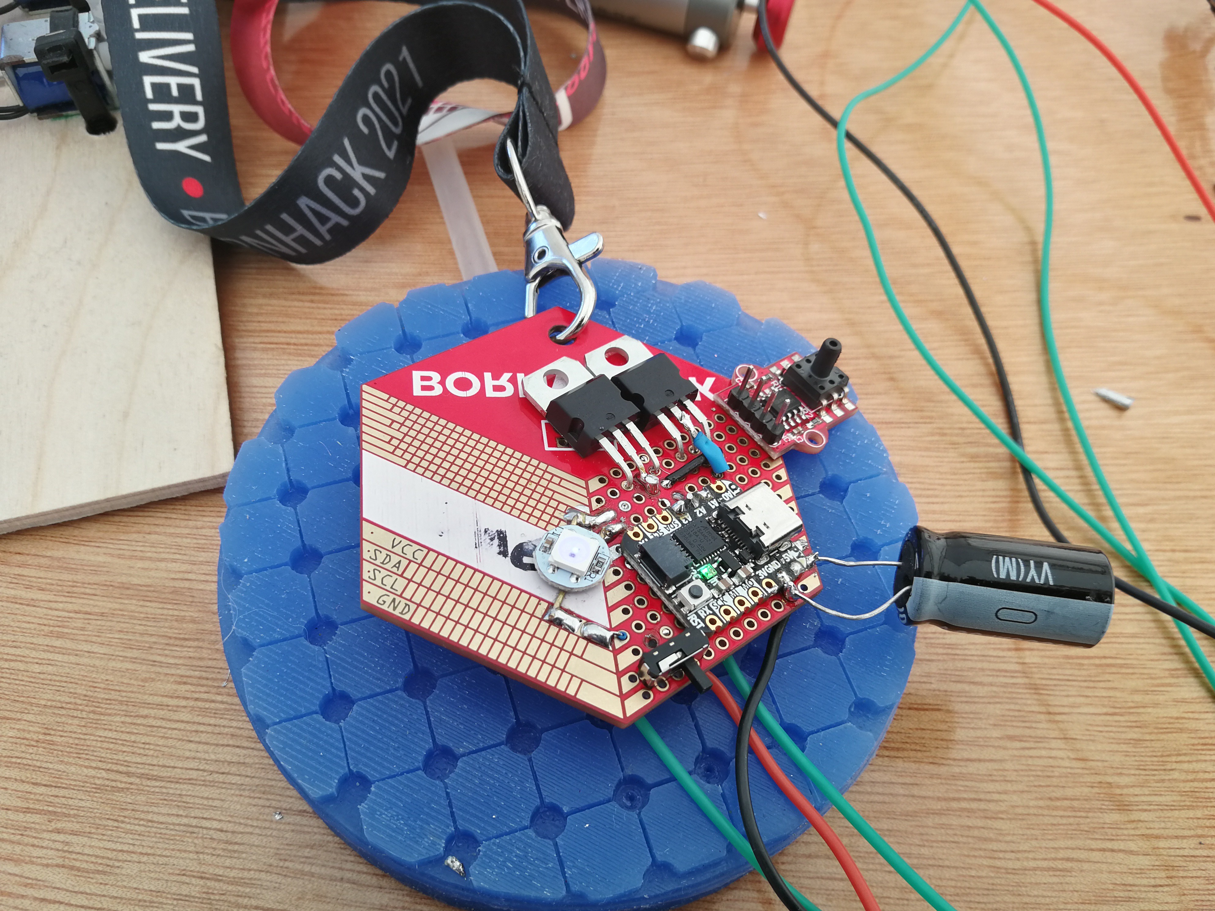
10Place 1000uF capacitor
The airpump takes a reasonable amount of current to get started, an amount that the batteries find hard to provide. On start up the voltage will drop and since our microcontroller is on the same power line this will cause it to reset. Running the start of its code again turning (at some point) the airpump on etc. So in order to prevent the brownout of the controller we place a big capacitor in paralell along the 5V and Gnd pins. In this case a 1000 uF capacitor is choosen. Pointing the cap outward of the badge so the bubble will still fit on top.
![]()
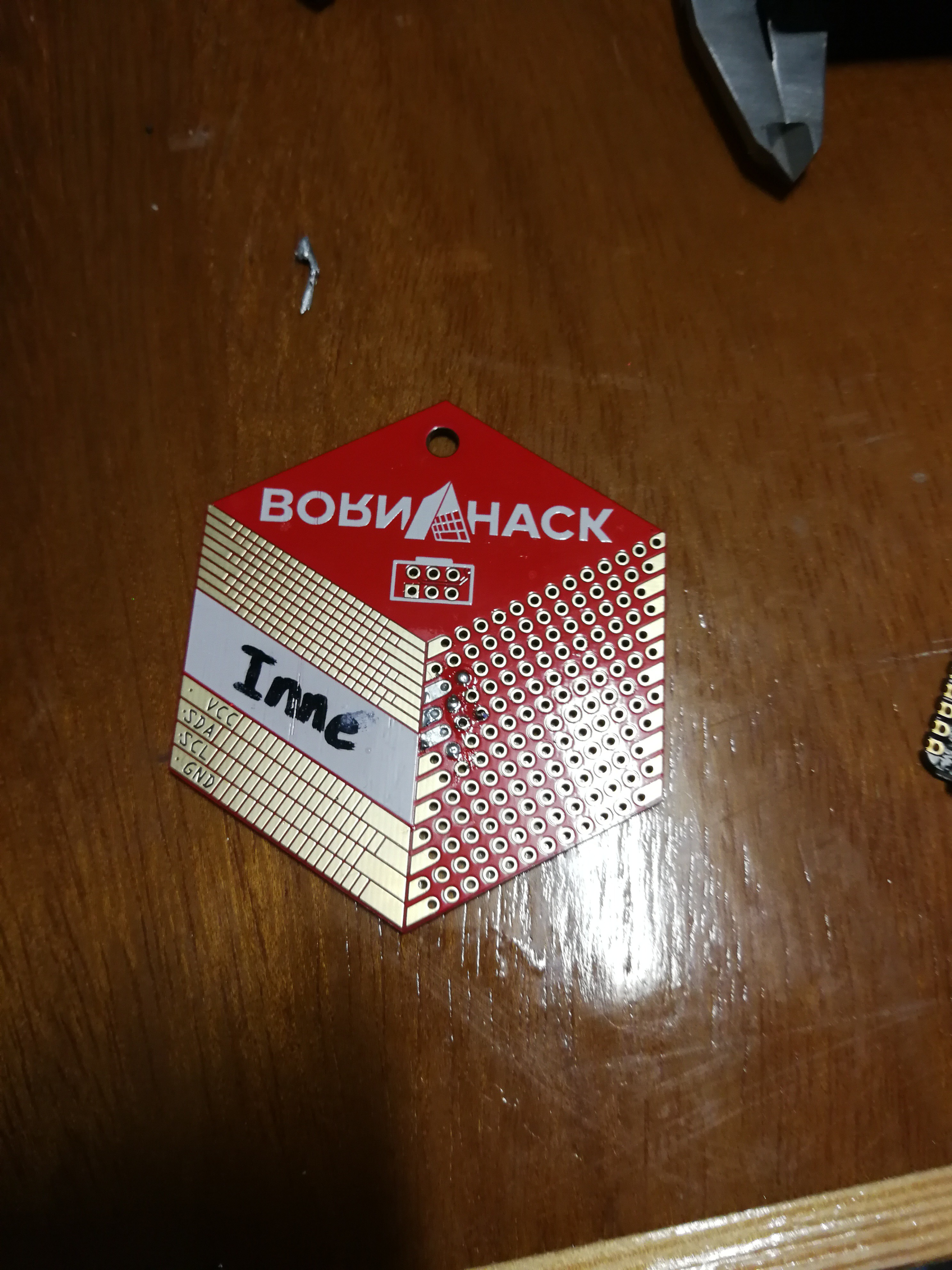
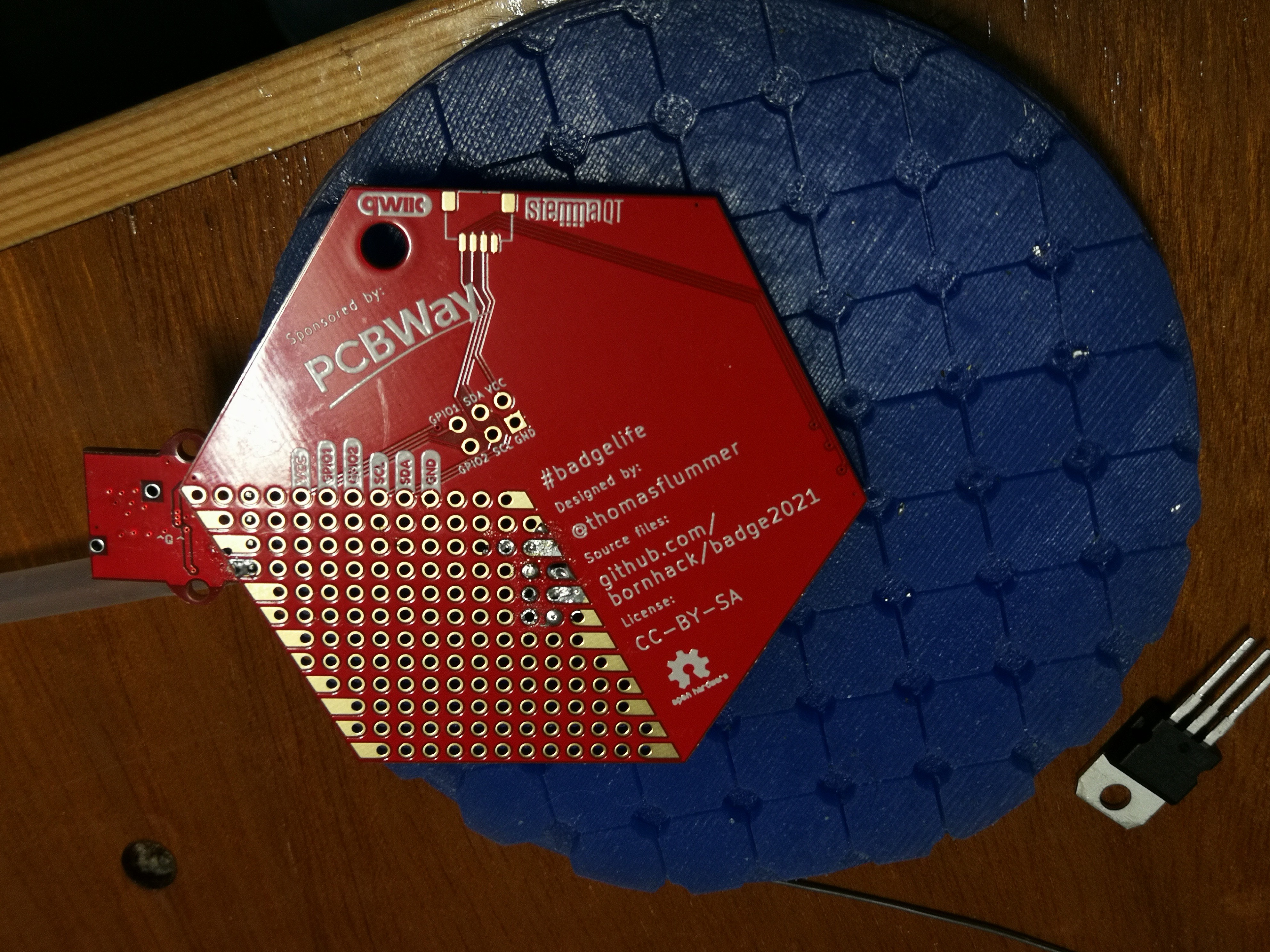
BornHack Bubble Badge
The BornHack 2021 badge was a PCB/prototyping board, I decided to make a smaller version of my soft robotic bubbles.
 In this picture the ground wire is already connected to GND and leads down to the battery connector. 5V will ve wired up in the next step.
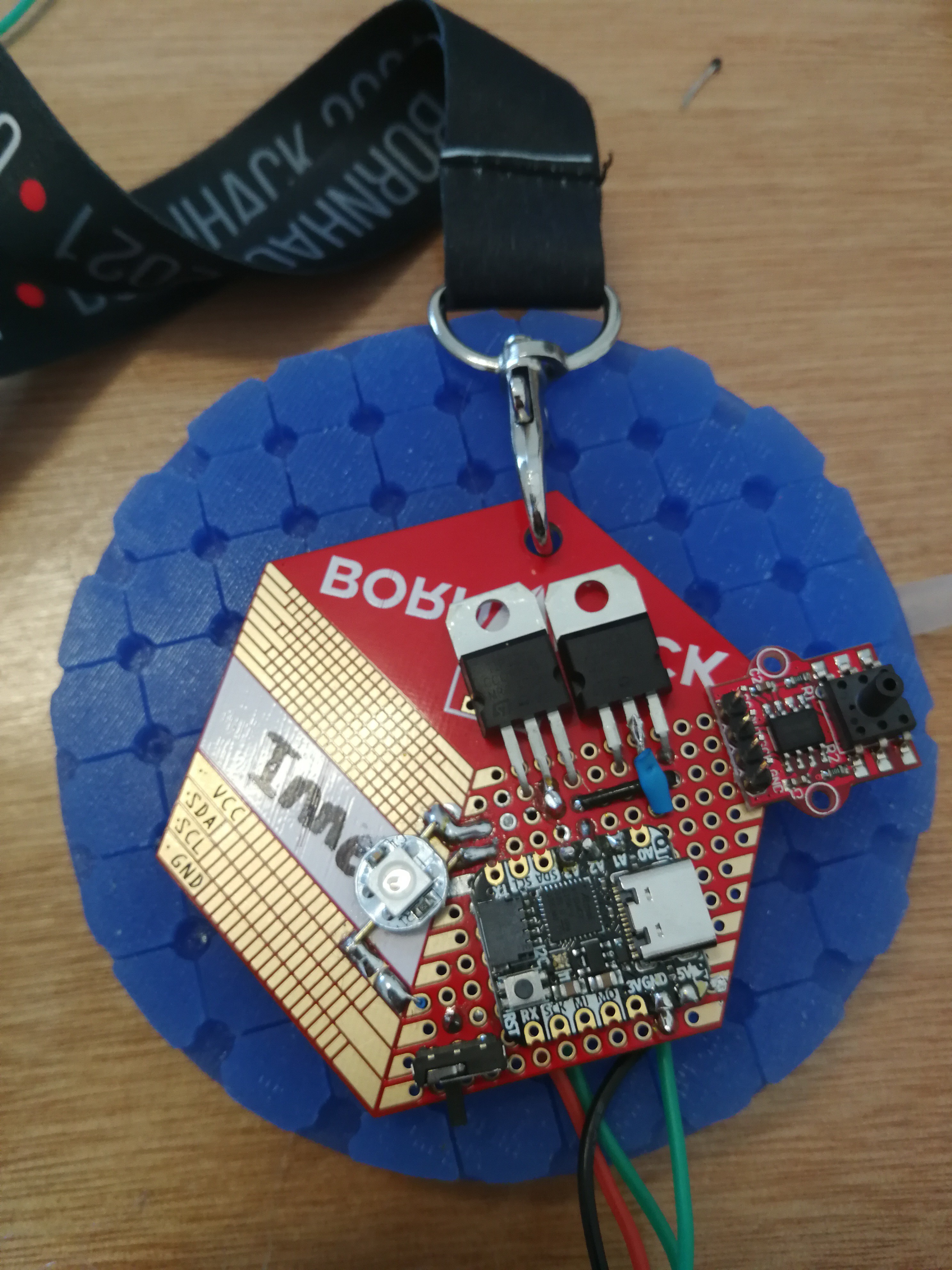 The wires should be connected with direct path to the emitter pin, so don't place them after the diode.
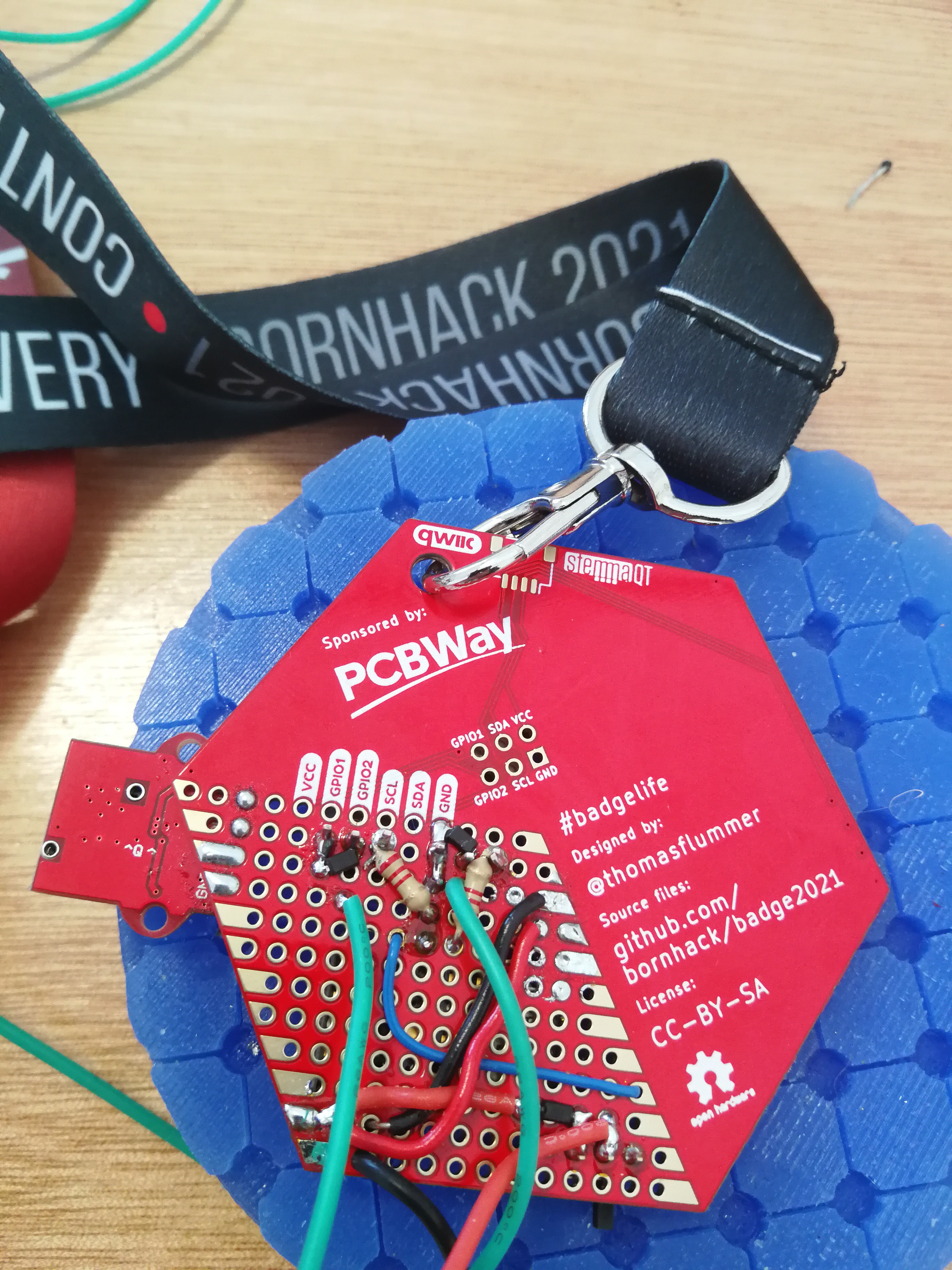 Also connect the middle pin of the switch with a wire that will go to the positive lead of the battery.
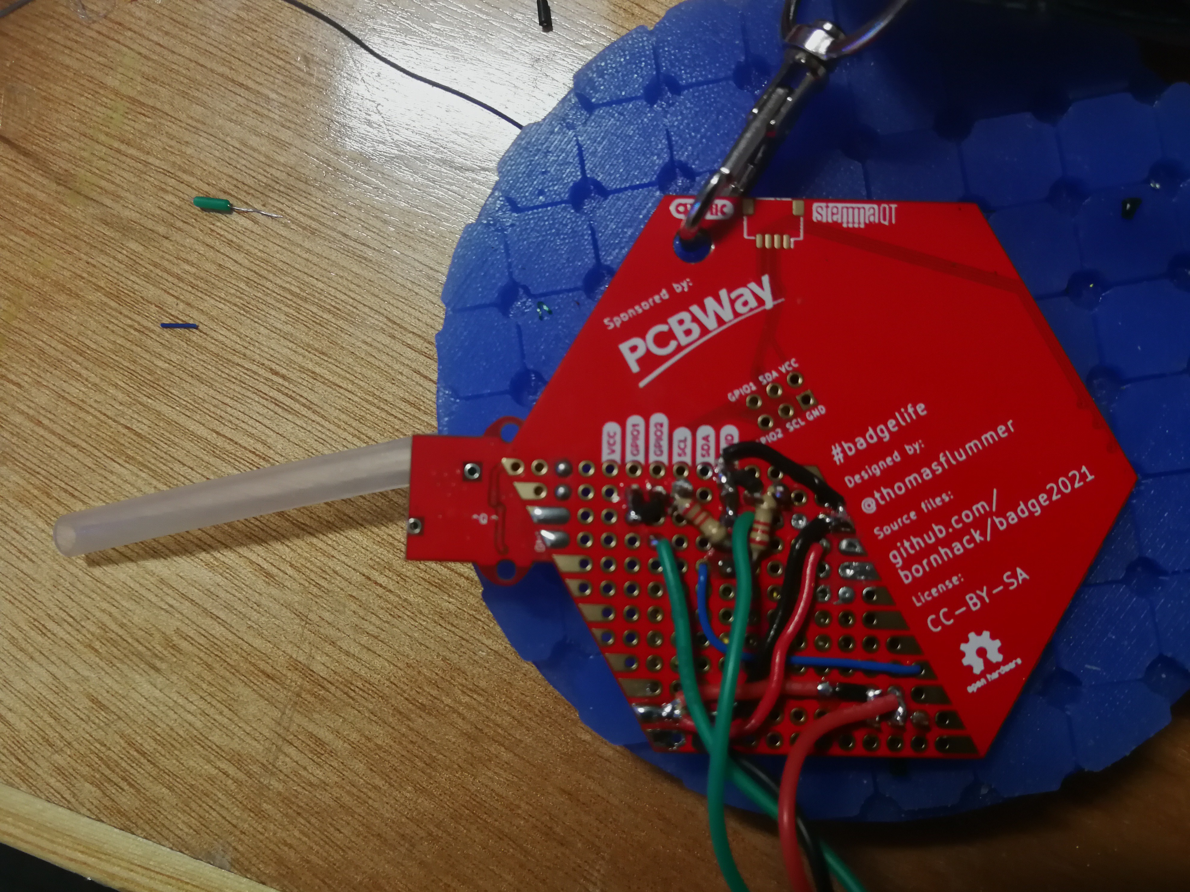

Discussions
Become a Hackaday.io Member
Create an account to leave a comment. Already have an account? Log In.