 --Oz--
I have a low cost 30V 10A 300W CV/CC power supply (~$50 on ebay) that I want to add a output on/off control function. With this supply you need to either turn the entire power supply off or disconnect the banana connection and vise versa for turning the output back on.
Goals:
- No bounce when output turns on or off (so no mechanical contacts for output current, IE: relay/switches/etc
- Control the positive output (not the ground connection).
- KISS design (Keep It Super Simple and low cost)
- Be able to control 0.1V to 30V and up to 10A
Here is my final schematic:
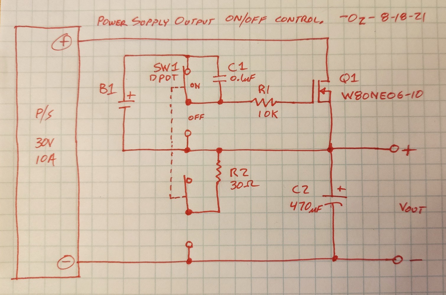
More details of how I finally got to this schematic after trying several variations.
Wanting to use n-fet and control the positive supply output (because I have a few flavors and they are lower RDSon (resistance), I needed a way to drive the gate of the n-fet above the output voltage to turn it on. Same thing using a p-fet, you need lower than 0 volts to turn it on when output voltage is under ~2V. I finally decided to use a rechargeable Li-Ion 18650 2S (2 cells in series, 7 to 8.4v), a switch, then a RC connected to the gate and a pull down resistor for turn off.
I really did not want to add the maintenance of a rechargeable battery, but there is good news, read on. Also 2 or 3 coin cells (CR2032 for example) can be used.
I started with battery, SPST switch, gate resistor, cap from gate to source, and a pull down resistor gate to source. The circuit needed some tuning to get a nice turn on waveform across 0.1v to 30v and 0 to 10A load. Many factors played into tuning the turn on/off waveform, like output voltage, output current, gate voltage, fet gate capacitance and all the passive components.
Larger R1 and/or C (across gate to source), the slower the turn on (and same with lower battery voltage). The lower the pull down resistor, the quicker the turn off. I noticed if I used too low of R1 resistance (fast turn on), the output waveform overshoots (up to 400mV), I did not like that so I kept raising the gate resistor to eliminate this issue. This could be from the cables to the resistive load (50uH).
Once I got it working fairly well, I noticed the battery current was dominated by the pull down turn off resistor. In order to make the battery last longer before needing to recharge, I found I could easily go up to ten megaohm (at 200K it was around 20uA when on), this should last more than 5 years before needed to recharge.
I wanted to add a output discharge circuit, so I changed the switch from SPST to DPDT, this opened up some new ideas. I could do away with the pull down resistor all together, so the battery ON current would be next to nothing (besides when charging the gate capacitance, of around 8nF). This will make the battery last for 10+ years. These Li-Ion cells have very low self discharge. I used some old cells from a discarded notebook, the cells only tested to 1300mAH, but for this application it is plenty of capacity.
After getting my circuit tuned well, I am always looking for the ultimate low cost KISS solution, I removed the R1 and C (so just battery/switch/fet) and just use the fets gate capacitance for debounce. This created very fast turn on times (not needed) but also ringing of the output voltage at start up that I did not like.
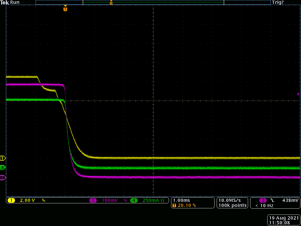
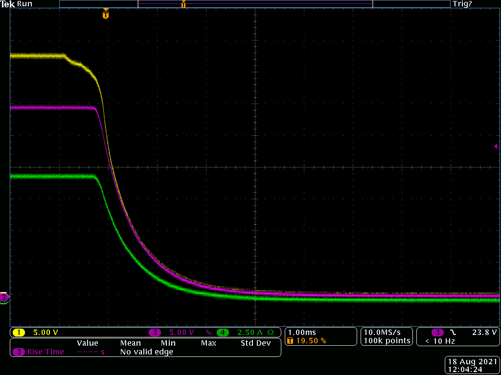
Scope Traces:
Yellow or Blue=gate
Red=Vout,
Green=Iout (current probe)
Here is the finished turn on at ~4 amps.
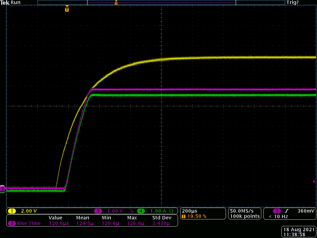
It took several tries to get it this way, below was my small journey, haha!
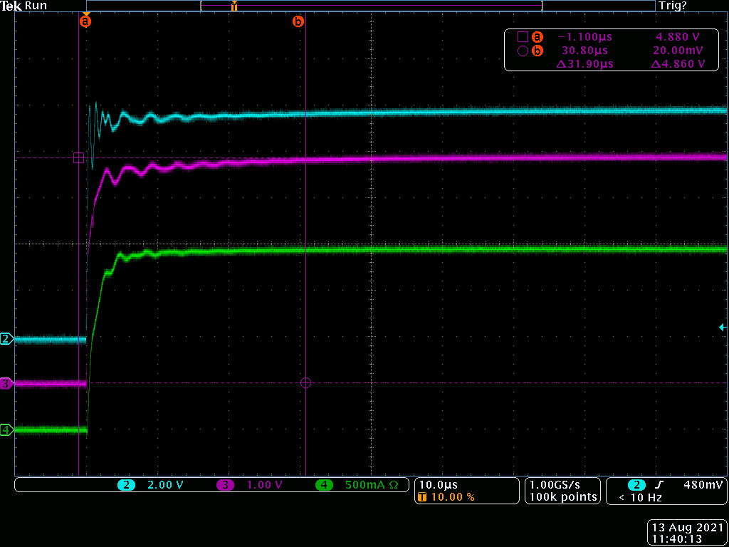
This also caused turn on overshoot under certain Vout/Iout conditions. So I added the gate charge resistor (R1) back in, but during testing I randomly found an interesting turn on waveform when the switch was bouncing open. You can see the gate voltage stop rising multiple times (reminded me of peak voltage detect circuit of the 80's I built for charging NiCD's for RC on-road cars) before final setting voltage, this does stop the bounce issue of the supply output voltage turning on/off multiple times, but of course I did not like this funky turn on voltage waveform. In this picture you can see 4 switch bounces, since the output voltage followed this waveform and so did output current, this was not acceptable.
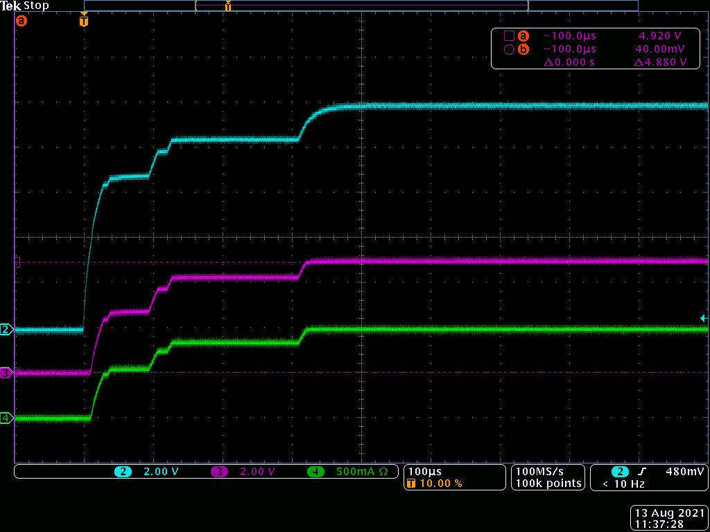
So solve this issue I tried a few things and then I tried the a cap across the switch contacts, this worked very well! This new circuit again needed some tuning for the different Vout/Iout conditions. At this point I am pretty happy with the turn on over all the Vout/Iout conditions.
Discharge:
After having a debounce and turn-ON solution that I was happy with, I added a output discharge circuit, its simply a switch and 10Ω 3W resistor, it works well.
Here is 0.5V at 890mA output turn off.
Here is 30V 9.9A output turn off.
FETs
I was first using a IRFZ48N (64A 55V TO-220), I did blow two of them up when testing at 25~30V and +9A, not exactly sure why, there is a high surge current during turn on from the charged caps charging the added output cap (C2). I tried a 16V zener across gate to source, but not sure its needed. It seemed like was when turning off is when they failed in the ultra KISS design (shorting gate to source, no slow down resistor). I decided to try a larger and lower RDSon STW80NE06-10 (60V 80A TO-247) and zero failures. I needed to tune the gate resistor again because the gate capacitance went way up (to 7.6nF) from the first fet.
Then I let the output sit turned ON at 30V 10A for 12 minutes, the fet Vds=84mV, so it was burning 840mW, it was on a heatsink at the time and slightly got warm. I will heatsink the fet to the bottom chassis (insulated of course).
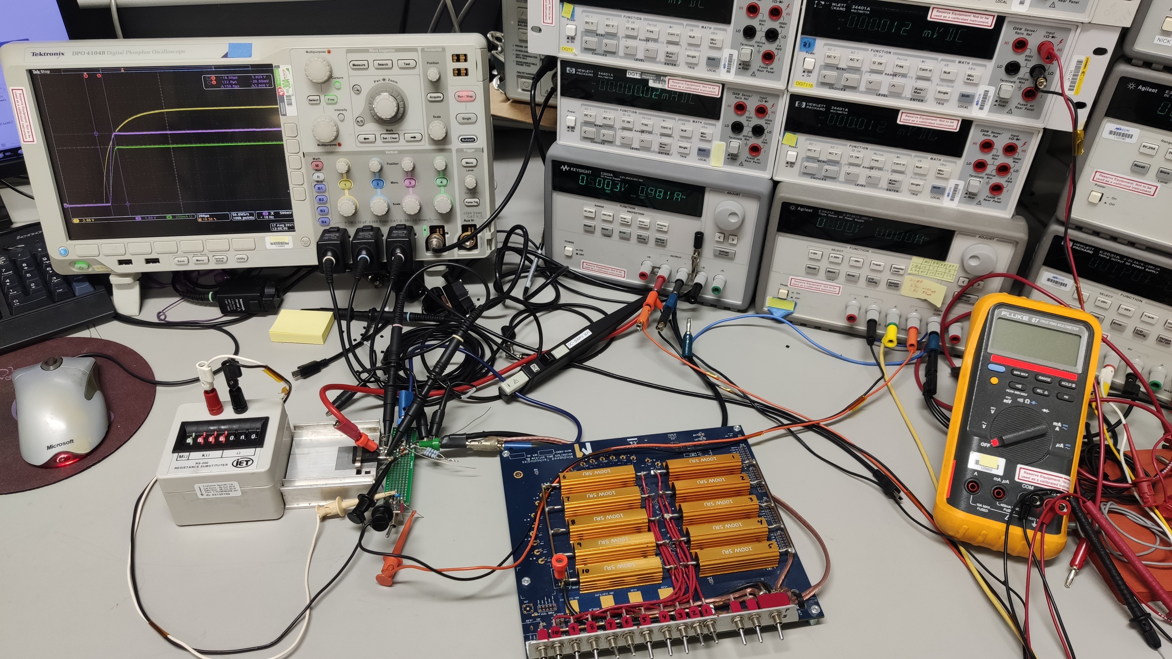
Load for testing:
My load for testing was made years ago for discharging unused LiPo batteries for my planes and quads. The resistive load is 5Ω 100W resistors in a parallel bank of 10 with switches to enable each one and a series/parallel switch (so 0.5Ω to 10Ω) and about 3 feet of speaker cable (~50uH inductance). These 100W resistors were found on ebay 10pcs for $11 shipped. I mainly use load this with my iCharger 306b in discharge+ mode (the 306b controls the current, the resistors take the heat (and not the charger). I also have a 500W CC electronic load I built, but I did not want a active circuit interfering with my turn on tuning, so I did not use it.
Here is my bench where I am trying different circuits and tuning.
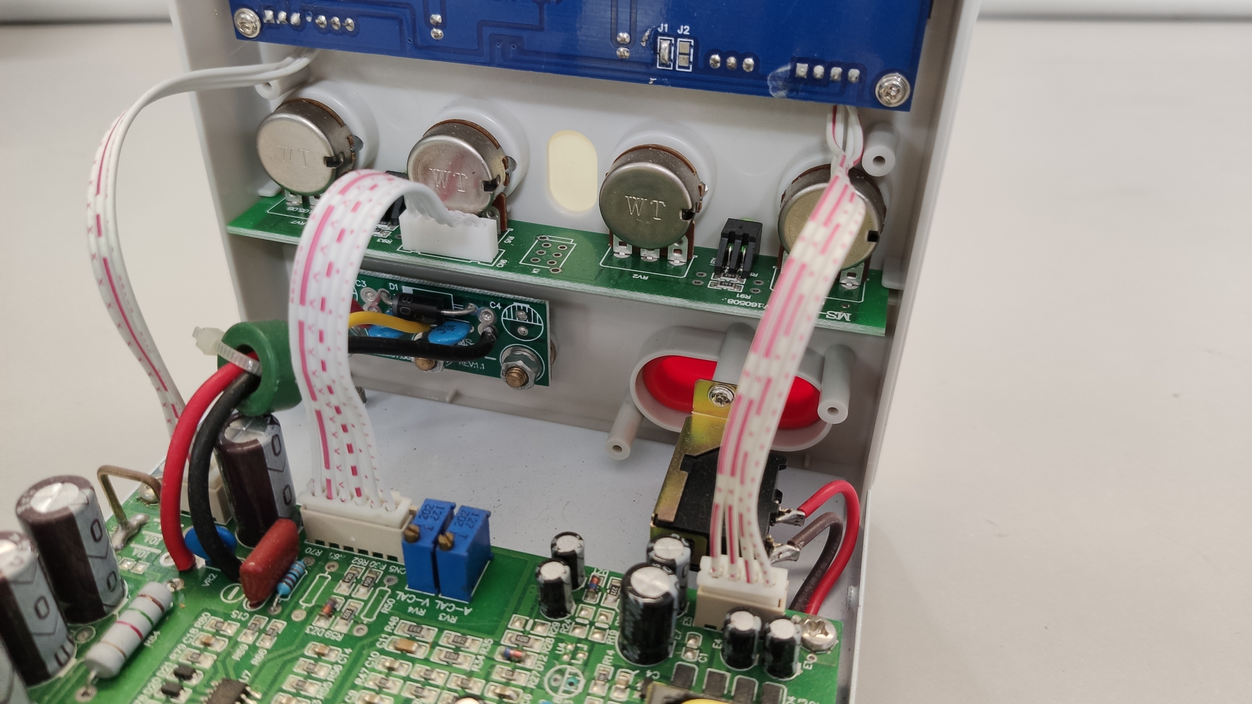
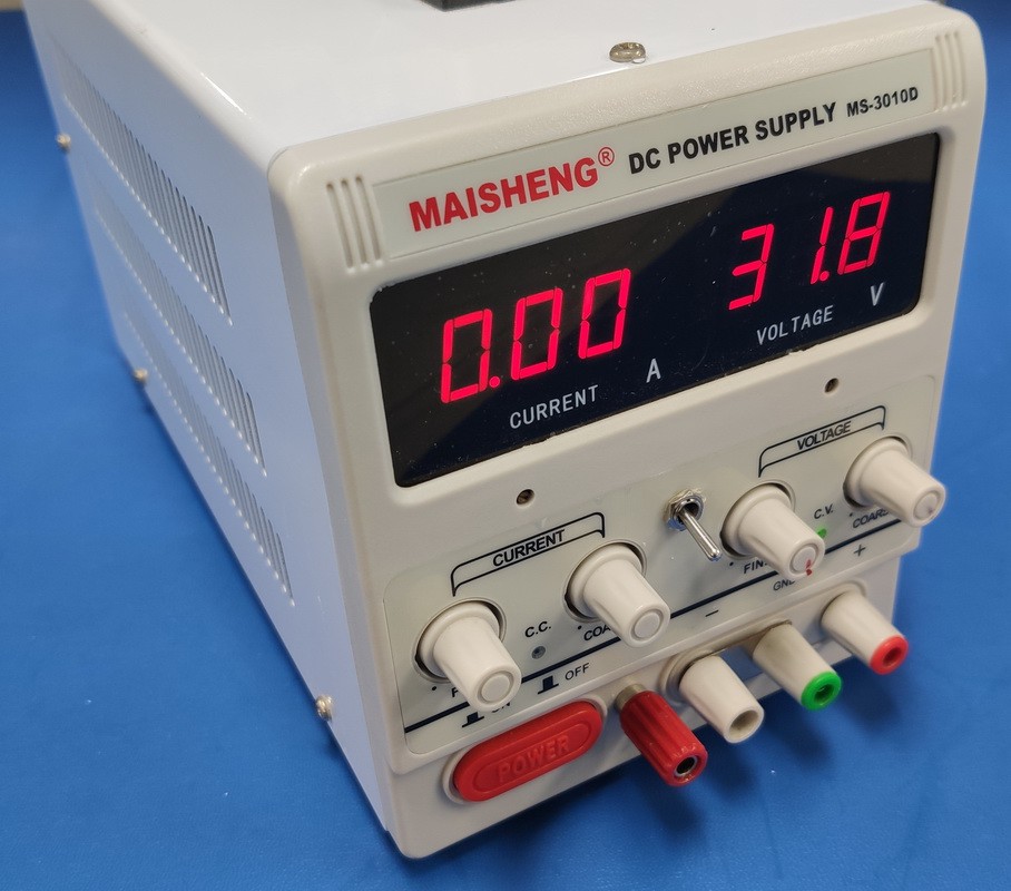
This is the stock power supply, for ~$50 its built very clean.
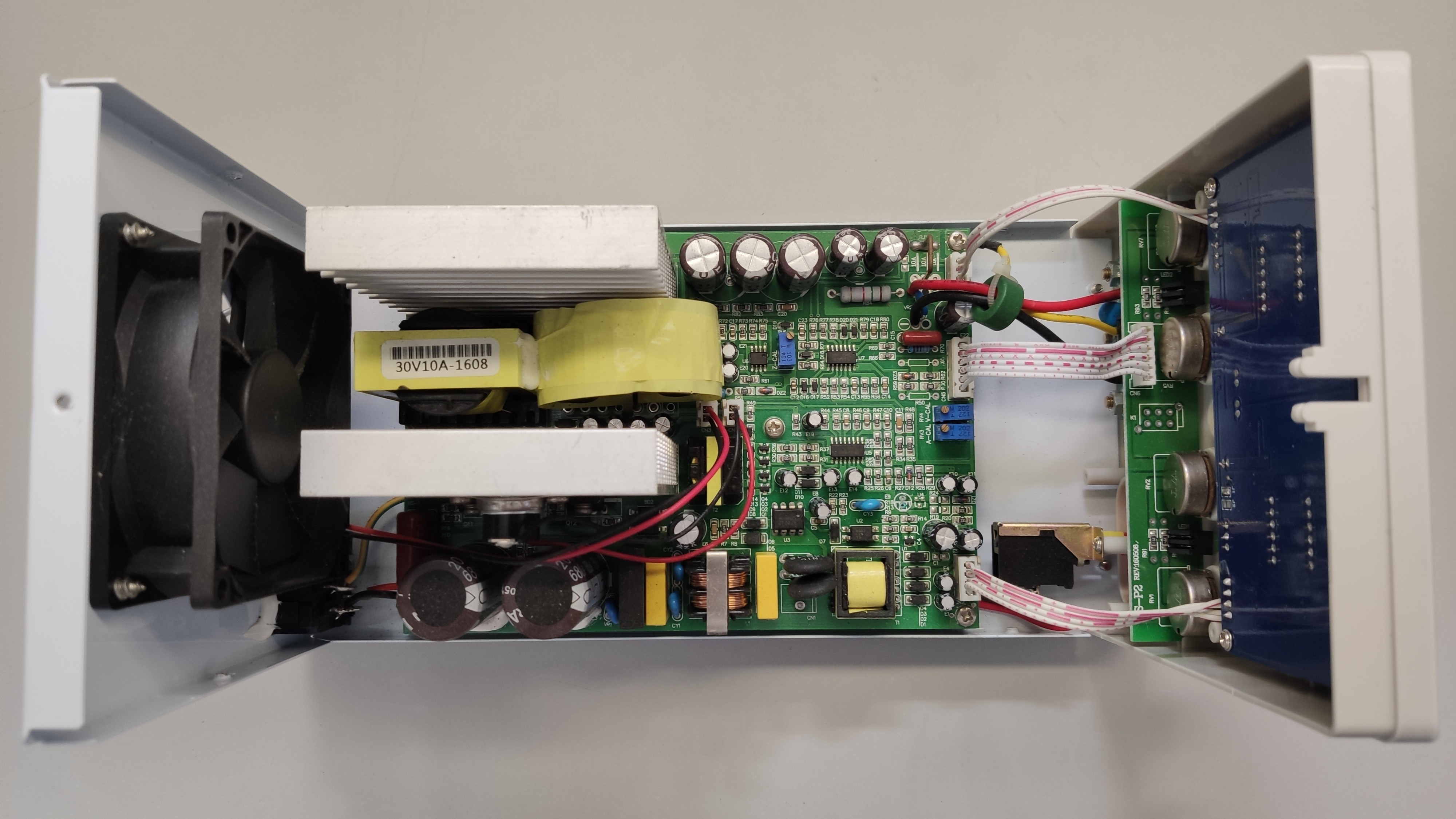
Lots of space to place my circuit and heatsink the fet to the chassis.
My circuit installed.
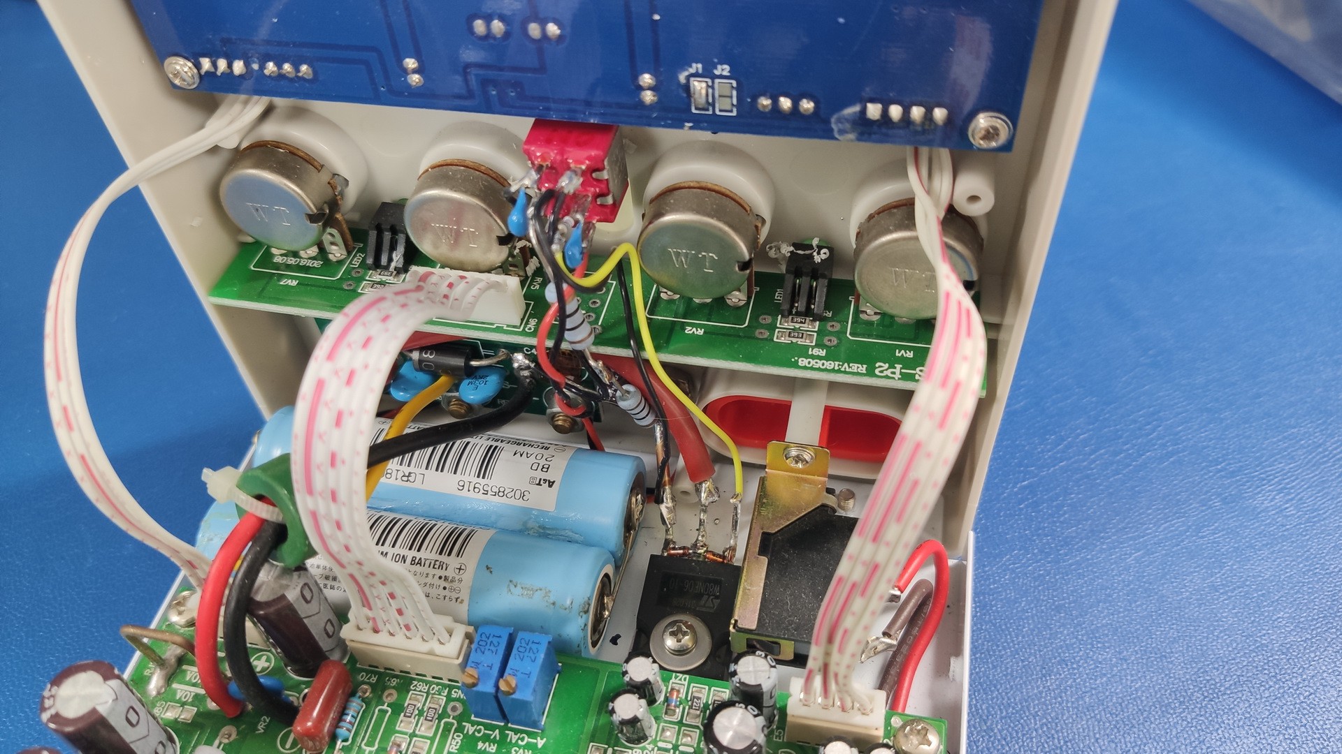
Output toggle position and added switched output banana post (on left).
Overall I am pretty happy with it.